Published in IET Communications Received on 19th March 2008 Revised on 24th September 2008 doi: 10.1049/iet-com:20080157
ISSN 1751-8628
Optimum detection of non-orthogonal QAM
signals with spectral overlapping
A.M.P. de Lucena
1
J.C.M. Mota
2
C.C. Cavalcante
2
1Northeast Regional Center, National Institute of Space Research-INPE, PO Box 21, Euse´bio-CE, Brazil
2Department of Teleinformatics Engineering, Wireless Telecommunications Research Group, Federal University of Ceara´-UFC,
PO Box 6005, Campus do Pici, Fortaleza-CE, Brazil E-mail: [email protected]
Abstract:The authors evaluate and propose two approaches for the detection of two non-orthogonal m-QAM signals with spectral overlapping through an AWGN channel. Some previously reported works are revisited and alternative solutions in order to permit their application in practical communication systems are proposed. The subject method is proved to be relevant because it does not obey the Riesz basis condition for performing signal separation. The optimum maximum-likelihood receiver for this detection problem is also derived and the performance analysis is presented, including some analytical and Monte Carlo simulation results.
1
Introduction
The orthogonality among waveforms makes possible the spectral superposition of signals in several communication systems improving the performance in terms of the frequency bandwidth. Quadrature phase-shift keying modulation, in which two orthogonal binary phase-shift keying (BPSK) signals at the same frequency band are added, makes use of orthogonality to double the spectral efficiency when compared with BPSK. Communication systems with multiple access strategies, such as OFDM
[1, 2]and CDMA [3], also increase the spectral efficiency using orthogonal waveform signals with frequency overlapping to transmit information from different sources.
On the other hand, there are several references in the literature about digital communication systems that use intentionally non-orthogonal signals to transmit information[4 –15]. Commonly, non-orthogonality is used when, because of channel impairments, it is not possible to keep the orthogonality among the transmitted signals. Therefore the approach with a non-orthogonal waveform represents more flexibility or efficiency in some aspects for communication systems.
The orthogonal multicarrier modulation OFDM is a very efficient method to high-data-rate wireless transmission[2].
Nevertheless, the classical OFDM, with rectangular pulse and orthogonal carriers, is not the best choice when the channel has time and frequency dispersion (doubly dispersive) [8, 10]. Various non-orthogonal multicarrier modulation systems have been proposed [8, 10–12] and present several potential advantages when compared with conventional OFDM operating in a doubly dispersive channel. A common characteristic of all these proposed systems is Df1/T, where Df is the frequency separation between the subcarriers and T the symbol period. That condition corresponds to the existence of Riesz bases, which ensures the linear independence of signals[8].
Differently, the fm-QAMg2 modulation scheme, presented in [13], transmits simultaneously two m-QAM non-orthogonal signals, with a frequency separation of Df smaller than the symbol rate in an ideal AWGN channel. However, the results of system performance of the fm-QAMg2 scheme of [13] are based on a non-rigorous hypothesis about the m-QAM signal bandwidth, as it will be discussed in the sequel. The assumptions considered in
[13] make the usage of the system quite limited and real-world applications are not able to profit from its gains.
modification into the fm-QAMg2scheme in order to make it feasible in practical systems, and present new results for the modified fm-QAMg2 receiver. Further, we derive the optimum receiver for the detection of two non-orthogonal m-QAM signals with spectral overlapping, and frequency separation less than the symbol rate, through an AWGN channel. Performance evaluation is assessed by means of analysis and computational simulations of the bit error rate (BER).
The rest of the paper is organised as follows. Basic assumptions of the problem are introduced in Section 2. The fm-QAMg2 scheme is revisited in Section 3. We derive the configuration of the optimum receiver and show some performance results in Section 4. Finally, in Section 5, our conclusions and perspectives are presented.
2
Problem definition and model
Two m-QAM signals are combined to form N possible transmitted waveforms si(t), i ¼ 1, 2, ..., N, with N ¼
m2, that can be expressed by
si(t)¼x1i(k) cos(2pf1t)y1i(k) sin(2pf1t)
þx2i(k) cos(2pf2t)y2i(k) sin(2pf2t) (1)
for (k21)TtkT, corresponding to the transmission time of the kth combined symbol. The signals x1i(k), y1i (k), x2i (k) andy2i (k), taken from the alphabet f+1, +3, +5, ...g, are statistically independent and define the
transmitted symbols at the discrete instant k. The symbol duration is T, and f1 and f2 are the carrier frequencies of
eachm-QAM signal. It is supposed thatf2.f1andDf ¼
f22f1,1/T in such a way that there is spectral
non-orthogonal overlapping between the two m-QAM transmitted signals in an overcritical condition [8]. For this case, the baseband pulses are supposed to be rectangular with unitary amplitude and duration T and are denoted byg(t).
The channel is considered AWGN and the signal at the receiver input is given by r(t) ¼ si(t)þn(t), where the
noise n(t) is supposed to be white and Gaussian with a power spectral density ofN0/2 and zero mean.
The problem discussed in this paper is how to detect the transmitted symbolsx1i(k),y1i(k),x2i(k) andy2i(k) from the received signalr(t).
3
f
m-QAM
g
2modulation revisited
The fm-QAMg2 receiver scheme described in [13] was proposed to detect two non-orthogonal m-QAM signals with spectral superposition for the case where Df,1/T. Nevertheless, in that paper, each m-QAM signal was considered to have a bandwidth equal to the symbol rate rs¼1/T and, consequently, the total bandwidth of the
fm-QAMg2 signal is presented as being W¼rsþDf.
Such a consideration is not strict and has a strong impact on the system performance.
The block diagram for thefm-QAMg2receiver is shown in
Fig. 1. The filter h(t) at the input of the receiver is an ideal band-pass filter with bandwidth equal to W¼rsþDf and
centred on the frequency f0¼(f1þf2 )/2. The received
signal r(t), after being filtered by h(t) in order to reduce the noise power, passes through four frequency converters producing the baseband signals a1(t), a2(t), b1(t) and b2(t)
that are integrated during each symbol periodTand sampled at time t ¼ kT, where k¼1, 2,.... Each one of the
frequency converters A1, A2, B1 and B2 includes two
multipliers, one adder and local oscillators. A linear transformation is applied to the sampled signalsa1(k),b1(k),
a2(k) and b2(k), aiming to separate the transmitted symbols
x1i(k), y1i(k), x2i(k) and y2i(k) that are detected by decision
circuits[13].
This receiver would have very good performance if the m-QAM spectrum was really limited to the bandwidth equal to 1/T. Nevertheless, the bandwidth occupied by an m-QAM signal is theoretically infinite when the transmitting pulseg(t) is rectangular in time[16]. The power density spectrum of the m-QAM signal,F(f), has the following form
F(f)¼K{ sin c2[(f fi)=rs]þsin c2[(f fi)=rs]} (2)
whereKis a constant,rsthe symbol rate andfiforj¼1, 2, the
carrier frequency of theithm-QAM signal. From (2), one can easily verify that only the main lobe of the signal spectrum occupies a bandwidth equal to 2rs. Therefore thefm-QAMg2
signals are strongly bandlimited by the front end band-pass filter h(t) in the receiver scheme proposed in [13]. On the other hand, it is a known result in the literature[17]that the bandlimiting in a QAM signal with rectangular modulating pulses causes amplitude distortions in each individual demodulated pulse as well as inter-symbol interference (ISI)
because of the time spread of the demodulated signal. For the case of fm-QAMg2, where two m-QAM signals are combined linearly, the situation is even worse than the single m-QAM case because, besides distortions and ISI for each individual demodulated m-QAM signal, there is also interference between the twom-QAM components.
For a singlekthfm-QAMg2transmitted symbol, the signal a1(t) indicated inFig. 1is given by
a1(t)¼x1i(k)g(t)he(t)þx2i(k)[g(t) cos(2pDft)]
he(t)y2i(k)[g(t) sin(2pDft)]he(t)þz(t) (3)
wherestands for convolution,g(t) the baseband pulse,z(t) a coloured baseband Gaussian noise andhe(t) a low-pass filter
that is related to the front end band-pass filter h(t) by the following equation
He(f)¼H(f f1)=2þH(f þf1)=2, forjfj f1 (4)
whereHe(f) and H(f) are the Fourier transforms of he(t)
and h(t), respectively. The first termx1i(k)g(t)he(t) in (3)
is the demodulated baseband pulse, which conveys the information aboutx1i(k). If theh(t) bandwidth was infinite, we should have x1i(k)g(t)he(t)¼x1i(k)g(t), which means that the demodulated baseband pulse should be exactly the same one transmitted. However, because of the limited bandwidth of h(t), the recovered pulse may be quite different from the transmitted one. Suppose the h(t) bandwidth W¼2rs (Df¼rs), which is the condition for
the largest bandwidth considered in [13]. Also, suppose only one fm-QAMg2 symbol is transmitted, in which the signal is assigned by x1i(1)¼1, y1i(1)¼1, x2i(1)¼1 and
y2i(1)¼1. The plot of the transmitted and demodulated
pulse, x1i(k)g(t)he(t) is shown in Fig. 2 where the
amplitude distortion and the time spread of the demodulated pulses can be noticed. The amplitude distortion reduces the energy of the demodulated pulse and
the time spread causes ISI. It is interesting to observe that the input filter affects in the same way as the second and third terms in (3), which means more power loss and interference between them-QAM signals.
In fact, the bandlimiting causes an important loss in the performance of thefm-QAMg2system in terms of the BER.
Fig. 3 shows the simulation results of the BER for thef 64-QAMg2 system with Df/rs¼1/3, taking into account the
signal distortion caused by the bandlimiting, compared with the BER for the condition when no distortion is considered
[13]. Fig. 3 also contains a curve of the BER for a conventional 512-QAM system and the BER of the modified fm-QAMg2described in the next paragraph.
A very simple modification in the original fm-QAMg2 system in order to avoid signal distortion is to replace the narrowband input filter by an all-pass linear-phase filter or a filter that has a bandwidth much larger than the symbol raters. Such a modification makes the bandwidth efficiency
of thefm-QAMg2system very poor but improves the BER performance in a very positive manner, as shown inFig. 3.
We have carried out performance analysis for the modified fm-QAMg2system[18], obtaining the following expression for the BER
BER¼log4 2m
1 1ffiffiffiffi
m p
Q
ffiffiffiffiffiffiffiffiffiffiffiffiffiffiffiffiffiffiffiffiffiffiffiffiffiffiffiffiffiffiffiffiffiffiffiffiffiffiffiffiffiffiffiffiffiffiffiffiffiffiffiffiffiffiffiffiffiffiffiffiffi
3 log2m
(m1)(1þDf=rs)d(Df=rs) Eb N0
s !
(5)
where the termd(Df/rs), defined as the superposition factor,
depends on the amount of frequency superposition between the two m-QAM constituent of the fm-QAMg2 signal, and Eb/N0 is the average signal-to-noise ratio (SNR) per
bit at the receiver input. The superposition factor d(Df/rs),
Figure 2 Waveform of transmitted and demodulated pulses
in (5), is greater than the analogous parameters defined in
[13]for all values ofDf/rs[18].
We have performed new calculations of the power gains of the modifiedf64-QAMg2system, withDf/rsequal to 1, 5/7,
1/2, 1/3, 1/5 and 1/11, and compared them with those of several conventionalM-QAM schemes as in[13]for a BER equal to 1025. The comparison of the results of[13]and the
ones obtained for the modified system is presented inTable 1.
It is evident fromTable 1that there is a reduction in the power gain in the modified f64-QAMg2 when compared with the results reported in[13].
Regarding the results obtained so far, we can formulate the following question: which receiver is optimal for such a system? The answer is addressed in the next section.
4
Optimum receiver
4.1 Fundamentals
The received signal, for thekth symbol, (k21)TtkT, can be expressed by
r(t)¼si(t)þn(t) (6)
wheresi(t),i¼1, 2,...,NwithN¼m
2, is given by (1), and
represents all possible transmitted waveforms when two non-orthogonal m-QAM signals are combined, and n(t) is the sample function of white Gaussian noise with a power spectral density of N0/2 and zero mean. The signals x1i(k),
y1i(k),x2i(k) and y2i(k) correspond to the waveformsi(t) for
thekth symbol.
Since the channel is AWGN, the optimum maximum-likelihood (ML) receiver can be implemented by the minimum distance detector[16]. Such a detector computes a set of N distances D[r(t), si(t)], as expressed by (7), for each kth time interval T, where i ¼ 1, 2, ..., N. This
detector must select the signal corresponding to the
smallest metric given by
D[r(t),si(t)]¼
ðkT
(k1)T
[r(t)si(t)]2dt (7)
An equivalent optimisation is to maximise, for each kth received symbol, the correlation metric C[r(t),si(t)],i¼ 1,
2,...,N, defined as
C[r(t),si(t)]¼2
ðkT
(k1)T
r(t)si(t)dt
ðkT
(k1)
s2i(t)dt (8)
Notice that the second term in (8) represents the energyEi(k) associated with the waveform si(t), transmitted at the time interval (k21)TtkT, and is given by
Ei(k)¼E2g [x21i(k)þy1i2(k)þx22i(k)þy22i(k)]
þ2[x1i(k)x2i(k)þy1i(k)y2i(k)]
sin(2pDf Tk) sin[2pDf T(k1)]
2pDf T
2 6 6 6 4 3 7 7 7 5
þ2[x1i(k)y2i(k)y1i(k)x2i(k)]
cos(2pDf Tk) cos[2pDf T(k1)]
2pDf T
2 6 6 6 4 3 7 7 7 5 9 > > > = > > > ; (9)
whereEgis the energy of the baseband pulseg(t) that is equal toT. We remark that the energyEi(k) is not only a function of the transmitted symbol defined byx1i(k),y1i(k),x2i(k) and y2i(k), but also depends on the time kandDfthat indicates the degree of frequency superposition.
Substitutingsi(t), in the first term of (8), by the expression of (1), we obtain the following expression for the correlation metric as
C[r(t),si(t)]¼{2[x1i(k)
ðkT
(k1)T
r(t) cos(2pf1t)dty1i(k)
ðkT
(k1)T
r(t) sin(2pf1t)dt
þx2i(k)
ðkT
(k1)T
r(t) cos(2pf2t)dty2i(k)
ðkT
(k1)T
r(t) sin(2pf2t)dt]
ðkT
(k1) s2i(t)dt}
(10)
The block diagram of one possible configuration that implements the optimum receiver is shown in Fig. 4.
It is interesting to observe from (10) and Fig. 4that the sampled outputs of the integrator and dump circuits are
Table 1 Gain off64-QAMg2systems compared with that of M-QAM schemes
Df/rsoff
64-QAMg2
M-QAM (M)
Previous gain from [13], dB
New gain, dB
1 64 ,0 0
5/7 128 1.78 1.82
1/2 256 3.58 2.48
1/3 512 4.48 2.22
1/5 1024 4.06 0.68
sufficient statistics for the symbol detection. Therefore these outputs are delivered to the box called metric optimisation, as indicated inFig. 4, which computes theNvalues ofC[r(t), si(t)],i¼ 1, 2,...,N, as it is defined by (10), and chooses
the set of symbols x1i(k), y1i(k), x2i(k) and y2i(k), which maximises that metric.
4.2 Performance analysis
Suppose the waveformsi(t) corresponding to a given symbol assigned by the set of signalsx1i(k),y1i(k),x2i(k) andy2i(k) is transmitted at time (k21)T,t,kT. The event ej is defined as being C[r(t), sj(t)].C[r(t), si(t)] for i=j. Therefore the error probabilityPi(k) for any of the possible symbols received at a discrete timekcan be expressed as
Pi(k)¼P
[
j=i ej
" #
X j=i
P[ej] (11)
where the first term on the right side of the equality represents the probability of union of all eventsejforj=i, andP[ej], in the second term, is the probability of eventej.
To determine the upper bound of the conditional symbol error probability described in (11), we first evaluate P[ej]. From (6) and (8), it is easy to verify that the event ej happens when we have
ðkT
(k1)T
n(t)[sj(t)si(t)]dt. 1 2
ðkT
(k1)T
[sj(t)si(t)] 2dt
(12)
Notice that the integral on the right side of (12) represents the distance between the signals si(t), sj(t), and D[si(t), sj(t)], exactly as it is defined by (7). When the waveforms
si(t) and sj(t) are non-orthogonal m-QAM signals, the distanceD[si(t),sj(t)] can be written as
D[si(t),sj(t)]¼Ei(k)þEj(k)Eg{[x1i(k)x1j(k)
þy1i(k)y1j(k)þx2i(k)x2j(k)þy2i(k)y2j(k)]
þ[x1i(k)x2j(k)þx2i(k)x1j(k)þy1i(k)y2j(k)
þy2i(k)y1j(k)]
sin(2pDf Tk) sin[2pDf T(k1)]
2pDf T
2 6 6 6 4 3 7 7 7 5
þ[x1i(k)y2j(k)þx1j(k)y2i(k)y1i(k)x2j(k)
y1j(k)x2i(k)]
cos(2pDf Tk) cos[2pDf T(k1)]
2pDf T
2 6 6 6 4 3 7 7 7 5 9 > > > = > > > ; (13)
Note from (13), that even for the same pair of symbols, the distance between them presents time dependence.
On the other hand, sincen(t) is a white Gaussian process, the left side term in (12) is a Gaussian random variable that we can denote asvwhose meanmvand variancesv2are easy determined as
mv ¼0, and sv2 ¼N0D[si(t),sj(t)]=2 (14)
Finally, from (12) and (14), the probability of event ej can expressed by
P[Ej]¼Q
ffiffiffiffiffiffiffiffiffiffiffiffiffiffiffiffiffiffiffiffiffiffiffiffiffi
D[si(t),sj(t)] 2N0
s 0
@
1
A (15)
and the upper-bound expression forPi(k) becomes
Pi(k)
X
j=i Q
ffiffiffiffiffiffiffiffiffiffiffiffiffiffiffiffiffiffiffiffiffiffiffiffiffi
D[si(t),sj(t)] 2N0
s 0
@
1
A (16)
Note, from (13) and (16), thatPi(k) iskandidependent for a given value of DfT. Consequently, considering that all the signals ofsi(t) are equally likely with a probability equal to 1/
N, the average symbol error probabilityPscan be evaluated as
Ps¼Llim!
1 XL
k¼1
XN
i¼1
(Pi(k)=N)
" #
=L (17)
From (16) and (17), it is possible to estimate the upper bound of the symbol error probability.
4.3 Numerical example
We have performed the calculation for the upper bound of the average symbol error probability, Ps, through the
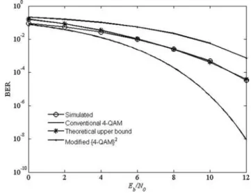
average of Pi(k), expressed by (16), over i and k, for the case when we transmit simultaneously two 4-QAM signals withDf T¼1/3. InFig. 5, it is shown the estimated upper
bound of the average bit error probability, Pb¼Ps/log2 N,
as well as the Monte Carlo simulation results for the BER, are both comparable to the average bit error probability of a single 4-QAM and the modified f4-QAMg2 presented in Section 3.
Observe fromFig. 5that the estimated upper bound of the average bit error probabilityPbagrees with the Monte Carlo
simulation results, and the loss of performance for two non-orthogonal 4-QAMs withDf T¼1/3, when compared with
a single 4-QAM, is about 2.5 dB at the condition of Pb¼1024; otherwise, the gain compared with that of the
modifiedf4-QAMg2is about 2 dB.
From (9) and (13), calculation shows that the minimum distance among the 16 possible symbols for two non-orthogonal 4-QAMs with Df T¼1/3, at any instant k, is
about 0.69Eg. In fact, since Df T¼1/3, each distance
between two given symbols can assume three different values as a function of k. Notice, in this case, that this minimum distance is smaller than the minimum distance for a single conventional 4-QAM signal, where this value is 2Eg. Such a difference of distance explains the results presented inFig. 5.
Fig. 6 illustrates Monte Carlo simulation results of the BER for the optimum detector for two 16-QAM signals, with Df T¼1/5, 1/3, 3/5, 2/3 and 1, compared with
those of a conventional 16-QAM receiver. We can see that the BER of the optimum detector with Df T¼1 is similar
to that of the conventional 16-QAM. This result was expected because two m-QAM signals are orthogonal when
Df T¼1. However, it is not expected that the
performances of the optimum receiver for Df T¼3/5 and
2/3 are also similar to those of the conventional 16-QAM as shown in Fig. 6. This means that there was an increase of frequency overlapping between the two non-orthogonal 16-QAM signals with no sacrifice in the BER. Observe also that the optimum detector for Df T¼1/3 and 1/5
needs an increase of about 2 and 4 dB of power at Pb¼1024to have the same BER as that of the orthogonal
case. The existence of a trade-off between power and frequency bandwidth is evident when we compare both the orthogonal and non-orthogonal cases.
Fig. 6results can be explained if we analyse the minimum distance among the symbols for each overlapping condition. In Fig. 7, the minimum distances between the 256 possible
Figure 5 Estimated and simulated BER of optimum ML receiver for two 4-QAM signals withDf T¼1/3 compared
with conventional 4-QAM and the modifiedf4-QAMg2
Figure 6 Simulated BER of optimum ML receiver for two 16-QAM signals with DfT ¼ 1, 2/3, 3/5, 1/3 and 1/5
compared with that of conventional 16-QAM system
symbols for the two non-orthogonal 16-QAMs are plotted as a function of Df T for k¼1 up to k¼5. Note that, from
Df T¼1 up to about Df T¼0.6, the minimum distance is
equal to 2Eg which is the same value as that of the orthogonal case. For Df T,0.6, the minimum distance starts to decrease, with a local maximum at Df T¼0.25,
and becomes zero for Df T¼0. The local maximum is
because of the orthogonality between the functions cos(2pf1t) and cos(2pf2t) for Df T¼0.25. The minimum
distance between symbols was also evaluated for two non-orthogonal 4-QAMs and 36-QAMs with the same phenomenon observed: from Df T¼1 up to about
Df T¼0.6, the minimum distance is almost the same as
that of the orthogonal case, as can be seen inFig. 8. This fact suggests an interesting alternative to increasing the spectral efficiency of multicarrier systems without any sacrifice of power.
The presented results show that it is possible to recover information transmitted through a communication system that utilises two subcarriers with Df T,1. There are indications in the literature that reliable data detection in such a condition may be difficult[11]or even impossible[8].
5
Conclusions
In this paper, the problem of non-orthogonal signals with spectral overlapping in the overcritical condition [8] is addressed, which is reported in the literature to be very difficult with regard to information retrieval since there are no Riesz bases for the Weyl–Heisenberg system[8, 11].
We have discussed the fm-QAMg2 receiver scheme presented in [13] and pointed out a misunderstanding concerning the signal bandwidth. A modification in the fm-QAMg2 receiver is proposed in order to improve the system BER, obtaining new performance results.
An optimum ML receiver was derived in order to detect two non-orthogonal m-QAM signals, with spectral overlapping, and carrier frequency separation less than the symbol rate, through an AWGN channel. The performance is assessed by theoretical analysis and computational simulation results. An upper bound for the BER is derived and proved to be a good approximation for BER evaluation.
It was demonstrated that the BER performance of the optimum receiver to detect two non-orthogonal 16-QAM signals is similar to that of the conventional 16-QAM within the condition that 1.Df T.0.6. This result implies that, in this case, there is a bandwidth gain without any sacrifice in the BER. Furthermore, for Df T,0.6, there is a trade-off between the BER and the frequency overlapping.
New investigations concerning the spectral superposition of m-QAM signals modulated by pulses with limited bandwidth have been the subjects of our studies. Further, our aim to find out the rationale of the proposed system is still a useful approach although it does not fit the condition to be a Weyl–Heisenberg system.
6
References
[1] WEINSTEIN S.B., EBERT P.M.: ‘Data transmission by frequency division multiplexing using the discrete Fourier transform’,IEEE Trans. Commun. Technol., 1971,COM-19, (5), pp. 628 – 634
[2] BINGHAN J.A.C.: ‘Multicarrier modulation data transmission: an idea whose time has come’, IEEE Commun. Mag., 1990, 28, (5), pp. 5 – 14
[3] PICKHOLTZ R.L., SCHILLING D.L., MILSTEIN L.B.: ‘Theory of spread-spectrum communications-a tutorial’, IEEE Trans. Commun., 1982, COM-30, (5), pp. 855 – 884
[4] SAU J.H.M.,SOUSA E.S.: ‘Non-orthogonal CDMA forward link offers flexibility without compromising capacity’. Proc. Int. Symp. Spread Spectrum Techniques and Application, Mainz, Germany, October 1996, pp. 530 – 535
[5] VARANASI M.K., RUSS A.: ‘Noncoherent decorrelative detection for nonorthogonal multipulse modulation over the multiuser Gaussian channel’, IEEE Trans. Commun., 1998,46, (12), pp. 1675 – 1684
[6] SINHA R., YENER A.,YATES R.D.: ‘Noncoherent multiuser communications: multistage detection and selective filtering’, Eurasip J. Appl. Signal Process., 2002, 12, pp. 1415 – 1426
[7] MCCLOUD M.L.,SCHARF L.L.: ‘MMSE multiuser detection for noncoherent non-orthogonal multipulse modulation’. Proc. ISIT 2000, Sorrento, Italy, June 2000, p. 356
[8] KOZEK W.,MOLISH A.F.: ‘Nonorthogonal pulseshapes for multicarrier communications in doubly dispersive channels’, IEEE J. Sel. Areas Commun., 1998,16, (8), pp. 1579–1589 [9] MA W.K., CHING P.C., WONG K.M.: ‘Maximum likelihood detection for multicarrier systems employing non-orthogonal pulse shapes’. Proc. 2000 IEEE Int. Conf. Acoustics, Speech and Signal Processing, Istanbum, Turkey, June 2000, pp. 2489 – 2492
[10] SCHAFHUBER D., MATZ G., HLAWATSCH F.: ‘Pulse-shaping OFDM/BFDM systems for time-varying channels: ISI/ICI analysis, optimal pulse design and efficient implementation’. Proc. 13th IEEE Int. Symp. Personal, Indoor and Mobile Radio Communications (PIMRC ’02), Lisbon, Portugal, September 2002, vol. 3, pp. 1012 – 1016 [11] HUNZIKER T., DAHLHAUS D.: ‘Iterative detection for multicarrier transmission employing time-frequency concentrated pulses’,IEEE Trans. Commun., 2003,51, (4), pp. 641 – 651
[12] STROHMER T.,BEAVER S.: ‘Optimal OFDM design for time-frequency dispersive channels’, IEEE Trans. Commun., 2003,51, (7), pp. 1111 – 1122
[13] GIRAUDO E.C.,BALDINI FILHO R.,SCARABUCCI R.R.: ‘On thef m-QAMg2modulation’,IEEE – Commun. Lett., 2001,5, (10), pp. 426 – 428
[14] DE LUCENA A.M.P.,MOTA J.C.M.,CAVALCANTE C.C.: ‘Detection of non-orthogonal PAM signal with spectral overlapping’. Proc. 6th IEEE Int. Workshop on Signal Processing Advances in Wireless Communications, New York, USA, June 2005, pp. 425 – 429
[15] DE LUCENA A.M.P.,MOTA J.C.M.,CAVALCANTE C.C.: ‘Optimum detector to non-orthogonal PAM signal with spectral overlapping’. IEEE VI Int. Telecommunications Symp. (ITS2006), Fortaleza, Brazil, September 2006, pp. 678 – 681 [16] PROAKIS J.G.: ‘Digital communications’ (McGrawHill, 1983, 4th edn.)
[17] JONES J.J.: ‘Filter distortion and intersymbol interference effects on PSK signals’,IEEE Trans. Commun. Technol., 1971,
COM 19, (2), pp. 120 – 132