Account
J. Braz. Chem. Soc., Vol. 23, No. 11, 1959-1971, 2012. Printed in Brazil - ©2012 Sociedade Brasileira de Química
0103 - 5053 $6.00+0.00
A
c
*e-mail: [email protected]
Recent Advances in the Development of Magnetically Recoverable Metal
Nanoparticle Catalysts
Liane M. Rossi,* Marco A. S. Garcia and Lucas L. R. Vono
Instituto de Química, Universidade de São Paulo, Av. Prof. Lineu Prestes 748, 05508-000 São Paulo-SP, Brazil
O objetivo deste Account é fornecer uma visão geral de nossas atividades atuais de pesquisa, as quais envolvem a síntese e modificação de nanomateriais superparamagnéticos para aplicação na área de separação magnética e catálise. Primeiramente, uma introdução ao magnetismo e à separação magnética é feita. Em seguida, estratégias sintéticas que têm sido desenvolvidas para gerar nanopartículas superparamagnéticas revestidas esfericamente por sílica e outros óxidos, com destaque a sistemas bem caracterizados e preparados por metodologias que geram amostras de elevada qualidade e que, a princípio, podem ser produzidas em maior escala, são discutidas. Uma série de catalisadores magneticamente recuperáveis preparados em nosso grupo de pesquisa pela combinação única de suportes superparamagnéticos e nanopartículas metálicas é destacada. Este
Account é concluído com observações pessoais e perspectivas neste campo de pesquisa.
The aim of this Account is to provide an overview of our current research activities on the design and modification of superparamagnetic nanomaterials for application in the field of magnetic separation and catalysis. First, an introduction of magnetism and magnetic separation is done. Then, the synthetic strategies that have been developed for generating superparamagnetic nanoparticles spherically coated by silica and other oxides, with a focus on well characterized systems prepared by methods that generate samples of high quality and easy to scale-up, are discussed. A set of magnetically recoverable catalysts prepared in our research group by the unique combination of superparamagnetic supports and metal nanoparticles is highlighted. This Account is concluded with personal remarks and perspectives on this research field.
Keywords: magnetic separation, magnetite, silica, nanoparticles, superparamagnetism, catalyst
1. Introduction to Magnetism and Magnetic Properties
Humankind’s awareness and fascination with magnetism date back to many centuries, at least 2600 years. Even the ancients observed that lodestone, a special kind of magnetite that is a natural permanent magnet, attracts iron. This mysterious behavior was pondered in philosophical discussions and writings. The lodestone also served as the basis of the primitive Chinese compass, which was known in Europe and used for navigation only after the year 1200. The compass made possible the great development of navigation in this period and also led to significant scientific discoveries, including observations of the Earth’s magnetic poles and declination of its magnetic field.1 The development of models and theories that allowed
the understanding of the magnetism phenomenon occurred much later in the 20th century, and stimulated the search
of alternative protocols for synthesizing novel magnetic materials with tuned properties according to the desired applications.
All materials are magnetic to some extent and have different levels of spontaneous magnetization or response to an applied magnetic field (H) depending mostly on their atomic structure and temperature. Materials like iron, cobalt and nickel can exhibit large spontaneous magnetizations under certain conditions, while most materials display little magnetism, even in the presence of an external applied magnetic field. The magnetization induced in a material by an applied magnetic field is given by
M = χH, where χ is the volumetric magnetic susceptibility
(dimensionless) and both M and H are expressed in A m−1. The materials are classified according to the values
(ca. −10−5). On the other hand, below a given temperature,
termed Neel or Curie, some materials exhibit ordered magnetic states and are magnetic even in the absence of an external magnetic field. These ordered magnetic materials are classified as ferromagnets, ferrimagnets and antiferromagnets.2,3 The magnetic susceptibility in ordered
magnetic materials is dependenton temperature and H, and such a dependence is easily detected through the shape of M-H magnetization curves at a given temperature. In ferromagnetic and ferrimagnetic materials,an irreversibility in themagnetization process in the presence of a magnetic field results in hysteresis loops in ordinary M-H curves. This is observed in materials comprised of large particles and magnetic domains, separated by domain walls. The hysteresis loops is related to the energy balance due to the domain wallmotions between adjacent magnetic domains when temperature and applied magnetic field are changed. This is particularly different when the size of the magnetic particles are comparable with the thickness of the domain walls and occurs in systems composed of small particles, typically < 100 nm. Under this circumstance, the magnetic particles are comprised of single magnetic domains and their magnetic moments can be visualized as just one large magnetic moment. Such a large magnetic moment is free to fluctuate in response tothermal energy, while the individual atomic moments maintaintheir ordered state relative to each other. This is the so called superparamagnetism,4
which is characterized by the absence of magnetic coercivity in M-H curves at certain temperatures and magnetic fields. The time required for spin or magnetization reversal, the relaxation time (τ), depends on the energy
barrier between the spin-up and spin-down states and temperature, according to: τ = τ0 exp(∆E / kBT),
5 where
∆E is the energy barrier to moment reversal, and kBT is the thermal energy. In the simplest case of uniaxial anisotropy, a relaxation process in which the magnetization flips around an angle of 180o, the energybarrier is given by ∆E = KV,
where K is the anisotropy constant and V is the particle volume. Every magnetic material has its own characteristic magnetic anisotropy constant K, but in the case of single-domain particles, K may be considerably different from its volumetric value due to the surface and form anisotropy contributions. At relatively high temperatures, the energy of the large magnetic moments of monodomain nanoparticles may exceed ∆E and they fluctuate between spin-up and spin-down states, giving rise to the so-called superparamagnetic state. In such a state, coercivity is absent and the M-H curves are similar to those observed in paramagnetic materials but with large magnetic moments. The superparamagnetic behavior can be experimentally accessed by time-dependent techniques, as ac magnetic
susceptibility, provided that its measurement time tm>> t, or more appropriately that the flipping of the magnetic moments is faster than the experimental timewindow. On the other hand, for t >> tm, the system is termed blocked, the flipping of the magnetic moments is slow and quasi-static properties are observed. Theblocking temperature TB
is defined as the mid-point between these two states, where t = tm.
The technological applications of magnetic properties of materials are innumerous, and include magnetic data storage, transport, separations, sensors, drug delivery systems, diagnosis and therapy.6,7 The magnetic properties
of magnetic nanoparticles, which are very important to establish the kind of application they are good for, are strongly dependent on their composition, size and shape.6,7 Therefore, the search for synthetic protocols in
which nanoparticles are prepared with high control on those parameters (composition, size, size distribution, morphology and solubility) is still under debate in the literature in order to tune morphology and magnetic properties to each application.8 The thermal decomposition
of iron complexes (Fe(acac)3 (acac = acetylacetonate), 9,10
Fe-oleates,11,12 Fe(CO)
5,13 etc.) leading to the formation
of magnetite and other ferrites is so far the most known chemical method to obtain nanoparticles with high control on particle size, size distribution and shape. The traditional approach to prepare colloidal iron oxides, which is based on the aqueous co-precipitation of Fe2+ and/or Fe3+ salt(s),14,15
does not reach the same control on nanoparticle size as the methods mentioned before, but is still very often used because it is simple, fast and cheap.
2. Magnetic Separation: from Biotechnology to Catalysis
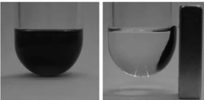
The intrinsic interaction of magnetic nanoparticles with external applied magnetic field gradients makes these materials attractive for transport and separation of attached entities that can range in size from molecules to nanoparticles. The large differences between the magnetic response to an applied magnetic field of magnetic and non-magnetic (diamagnetic) materials can be exploited in developing highly selective separation methods. Superparamagnetic nanoparticles, described above, essentially behave as non-magnetic materials in the absence of an applied magnetic field. However, they behave as paramagnetic materials in the presence of an applied magnetic field.6 In fact, these particles behave like
reduces the overall net magnetic moment back to zero. Thus, the nanoparticles have no “magnetic memory”, and they can be used in successive numbers of separation cycles, as far as their composition, morphology and size are preserved, making these particles highly interesting as vehicles for magnetic separation. There is a critical particle diameter, bellow which the nanoparticles exist as magnetic monodomains, and for typical material it is in the range of 10-800 nm (this superparamagnetic limit diameter is material-specific).6,16,17 Nanoparticles with
a diameter larger than this limit become resistant to the thermal demagnetization effects, outlined above, and thus will exhibit an undesirable “magnetic memory” after being exposed to an applied magnetic field, and will remain attached to each other. For magnetic separation, it is important that the magnetic nanoparticles have no “magnetic memory”, hence a non-magnetic material or entity attached to the magnetic material in this state can be separated, by applying a remote magnetic field, and then redisperse immediately after ceased the applied field.
Magnetism was first used to separate magnetic from non-magnetic components of a mixture, for example, for the enrichment of low-grade iron ore, removal of ferromagnetic impurities from large volumes of boiler water in both conventional and nuclear power plants, and removal of weakly magnetic colored impurities from kaolin clay.18 In the 1970s, magnetic separation began
to receive a lot of attention in biosciences, first to purify cells, cell organelles, and biologically active compounds (nucleic acids, proteins, etc) directly from crude samples. Chemically modified nanoparticles (NPs) with general specificity ligands (e.g., streptavidin) and chemically modified nanoparticles with specific recognition groups (e.g., antibodies) are used for the isolation of specific molecules through complementary binding interactions.19-21
In the same period, the immobilization of enzymes (as for example, lipase) in magnetic materials has become an interesting approach for the recovery and separation of biocatalysts.22 Magnetic affinity chromatography
also received attention as a separation technique in biotechnology.20
Magnetic separation using superparamagnetic nanoparticles and hybrid magnetic nanomaterials with organic or inorganic coatings, that can be modified with specific recognition groups, was first applied for cell sorting and separation of biologically active components, but later received attention in other fields of application, such as for heavy metal recovery23-25 and catalyst separation.26
Magnetic separation has several advantages in comparison with other traditional separation techniques as it avoids the use of solvents and other costly consumables, also
avoiding mass loss, which is intrinsic to these techniques. Additionally, the target component can be isolated directly from crude samples such as blood, soil, food, or any other complex fluid, which greatly simplifies the separation process as it avoids laborious filtration or centrifugation steps, saving time and energy. High selectivity can be achieved by means of the functionalization of magnetic nanoparticles with specific ligands to target the components of a mixture. The whole separation process can be performed without removing the sample from the flask or container, which greatly simplifies procedures such as repeated washing steps. The performance depends on two key magnetic components, the magnetic NPs and the magnetic field used to separate them. The field is usually generated by permanent magnets or electromagnets. Simple magnet blocks typically generate field gradients in the order of 1-6 T m–1, and magnet separators with significantly
higher field gradients can be designed.27 In addition, the
selection of the magnetic material, shape, size and size distribution of the nanoparticles will significantly affect the end separation results.
Magnetic separations fall into two general types: those in which one or more components to be separated of a mixture are intrinsically magnetic, and those in which they are attached to a magnetically responsive solid. Magnetic separation can be, in principle, used for the recovery of catalysts based on iron, cobalt and nickel and the corresponding oxides, but most of the time, magnetic supports are designed to separate “non-magnetic” catalyst components, such as metal complexes, metal nanoparticles, biocatalysts or organocatalysts (Figure 1). The efficiency of the magnetic separation is highly dependent on the quality of the magnetic nanoparticles or nanocomposites and on the stability of the linkage between the magnetic support and the “non-magnetic” component. This, in turn, allows separation of the final product, while the catalyst can be recycled and reused, without removing it from inside of the reactor, which is especially important for the case of air sensitive catalytic systems. Moreover, any possible loss
of catalyst due to transfer steps is minimized. In the next section of this work, our efforts on the design of high quality magnetic supports and catalysts are presented.
3. Advances in the Development of Magnetic Responsive Supports
Iron, cobalt, nickel and their corresponding oxides exhibit intrinsic magnetic properties that can be, in principle, used to separate them with a magnet from liquid phase solutions. However, “non-magnetic” catalyst components must be immobilized in magnetic responsive supports, mostly comprised of magnetic nanoparticles (iron oxides, in particular, magnetite28 or pure metals, such as
cobalt,29,30 because their high saturation magnetization)
that are used as prepared or coated with organic polymers, carbon or silica. In this coating process, the major challenge is how to control the loading and distribution of superparamagnetic components in the matrix material and to achieve monodispersity of the final product. Any heterogeneity (for example, matrix material without the magnetic core) or polydispersity (various sizes, which means various response to the applied magnetic field) is clearly a disadvantage because it may result in a large difference in response to the applied magnetic field and inefficiency in the separation process.
3.1 Coating magnetite with silica
Silica has been the first choice in the design of magnetic supports due to the high stability, versatility to functionalize the surface silanol groups and widespread use in biotechnology and catalysis (mainly as catalyst supports). Although the literature concerning the coating of ferrite nanoparticles with silica is vast and includes different levels of success in the coating process,31-47 the deposition
of a uniform layer of silica individually enclosing each nanoparticle (core-shell type) is not easy to obtain. The first method that our group tested was the basic hydrolysis of tetraethylorthosilicate (TEOS) in ammonia and alcohol, which is a modification of the well-known Stöber method for the synthesis of spherical silica.48 Magnetite nanoparticles
synthesized by the co-precipitation method stabilized with tetramethylammonium hydroxide and the commercial ferrofluid EMG 304 (Ferrotec, Nashua, USA), already described in coating processes,32 were used as magnetic
cores. Regardless the origin of the magnetic particles used, our group was not able to obtain a well-dispersed core-shell material, but ill-defined aggregates of magnetite and silica were obtained instead. Possibly, the main problem of this procedure is the poor stabilization of the colloidal solution
after the addition of alcohol and ammonia. It was observed flocculation of magnetic nanoparticles even before addition of TEOS. Using the commercial ferrofluid EMG 304, precipitation occurred after addition of isopropanol, and our group was not successful either. Several attempts were made to find the most appropriate ratio of water and alcohol required for stabilizing a colloidal solution prior to the addition of TEOS, but all have failed. To avoid flocculation of the magnetic nanoparticles in alcohol, it was followed a methodology proposed by Philipse et al.31
They suggested a pre-coating step in which the magnetic nanoparticles were treated with sodium silicate to change the nanoparticle isoelectric point and to stabilize the colloidal solution under the reaction conditions; thus making it possible to dilute the magnetic nanoparticles in alcohol (ethanol or isopropanol) and ammonia in the required ratio for the condensation of silica without the formation of undesirable precipitates. A set of reactions was carried out at different ratios of magnetite:TEOS. The samples were analyzed by transmission electron microscopy (TEM), which revealed particles in the range of 30-40 nm, with predominance of aggregates in a pearl necklace-like-structure. The material, so obtained, was used in applications that included immobilizing of drugs for biomedical applications,49 as well as catalysts for magnetic
separation.50 Because it requires high dilution of the coating
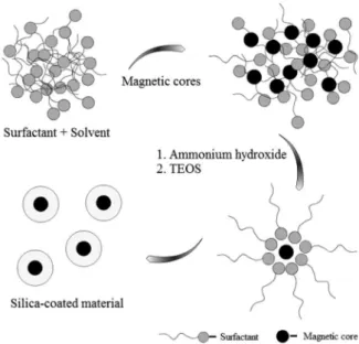
solution, this method limits the amount of material obtained to hundreds of milligrams in each reaction. In the search for high-quality materials, our group choses to adhere to the literature that shows monodisperse spherical materials obtained with the formulation of microemulsions, where the micelles or reverse micelles act as nanoreatores controlling the spherical morphology.33,34,51,52 Our first attempt
was based on a microemulsion prepared with aqueous solutions of magnetite nanoparticles stabilized with tetramethylammonium hydroxide or sodium silicate added to cyclohexane, TEOS, surfactant (Triton X-100) and co-surfactant (n-hexanol). However, after several hours, a silica rich material with ill-defined morphology precipitated. A formulation with the surfactant AOT (bis (2-ethylhexyl) sodium sulfosuccinate) was tested, but after the addition of ammonia, it also precipitated. Organic solutions of magnetite nanoparticles prepared by co-precipitation and stabilized with oleic acid were used in the formulation of a reverse micellar microemulsion with cyclohexane, TEOS and surfactant (Igepal CO-520) (Figure 2), a modification of the method reported by Yi et al.34 This
microemulsion resulted in high-quality nanomaterials with spherical morphology.
The material, named as Fe3O4@SiO2, consists of silica
the core coated with a uniform silica layer of approximately 20 nm, as observed in the TEM images (Figure 3). The synthetic procedure could be scaled up to a microemulsion of 2.8 L, from which it was possible to obtain 6-7 g of magnetic support in each reaction, while keeping the high control on the size and core-shell like nanostructure, as obtained before. The magnetic nanocomposite exhibits a saturation magnetization of 9 emu g-1 (total mass of
material) at 300 K, which corresponds to 69 emu g-1 of
Fe3O4 (Figure 3). This value is very close to the saturation
magnetization of the magnetite nanoparticles synthesized by co-precipitation and used in the preparation of the magnetic composite (62 emu g-1).53 The absence of
coercivity at 300 K is an important feature of the M-H
curve, which confirms that the properties of magnetic nanoparticles after the coating with silica were preserved. The material obtained is far superior in terms of morphology control and particle size than those prepared before and has been applied in our group as a support for a variety of applications in drug delivery, separation of enzymes and catalysts.53-58 Another interesting feature is
that the thermal stability of the magnetite nanoparticles was increased after the coating with a layer of silica. The pure magnetic nanoparticles loose the magnetic properties after thermal treatment (500 °C, 2 h, air), while the silica-coated magnetite preserved its magnetic properties. Additionally, the core-shell like morphology and mean particle size were preserved, as observed in the images obtained by TEM before and after calcination. The specific surface area increased approximately six times from ca. 20 to 110 m2 g-1
after calcination (unpublished results).
The reverse micellar microemulsion method used to synthesize silica-coated magnetic nanoparticles is very efficient, reproducible, and easy to scale-up, while maintaining a well-defined core-shell like morphology. Nevertheless, this synthesis generates a considerable amount of chemical waste, mainly because of the solvents and the surfactant used. In order to become economically and environmentally sound, our group was concerned about the waste produced. After precipitating the nanoparticles from the microemulsion by addition of methanol, it was obtained a three-phase mixture residue. The upper liquid phase contains cyclohexane as the major component, the intermediate liquid phase contains methanol and the third phase contains a brown solid (mainly, surfactant and iron oxide). Considering the fact that the surfactant increases the solubility of those solvents, and that it is not possible to recover them using simple decantation or distillation (cyclohexane and methanol, boiling points at 64.7 and 80.8 °C, respectively, form an azeotropic mixture, boiling point at 54.2 °C), our group had to find another way to separate those solvents Figure 2. Schematic representation of the preparation of silica-coated
magnetite by a reverse microemulsion.
(unpublished results). The upper liquid phase was treated in a very simple way, using distillation techniques. This procedure allowed the separation of pure cyclohexane and methanol. The intermediate liquid phase was distilled, giving a mixture of cyclohexane and methanol free of surfactant. This mixture, on standing, formed a two-phase system, and both phases were redistilled to give pure cyclohexane and methanol. In order to get a still better recovery, the lower phase was placed in a cooling chamber. This allowed again the formation of two-phase system, which could be distilled too. The given procedure allowed the recovery of large quantities of cyclohexane and methanol used in the preparation of our magnetic support. The solvents recovered were already reused showing no difference in the quality of the final material. Our group is still studying a way of purify the surfactant. Separation in silica column gave a viscous material that looks like Igepal CO-520 (nuclear magnetic resonance (NMR), termogravimetric analysis (TGA) and CHN elemental analysis), but further analyses are in progress.
3.2 Going beyond silica
Coating magnetic nanoparticles with polymers and silica shell is the most common approach for protection and modification of magnetic cores for biomedical applications;7,59-61 however, for catalytic applications there
are other possibilities that can be even more interesting.26
The main role of the silica/polymer shell is to prevent any direct contact of the magnetic core with additional reagents to avoid unwanted interactions, such as acidic corrosion or oxidation. The presence of a silica layer facilitates the characterization of metal nanoparticle catalysts (see discussion bellow) and the control of metal dispersion by the means of surface modification with organic functional groups. Silica is pretty stable (except in basic media) and does not show intrinsic catalytic properties. Other inorganic oxides, such as titania, alumina and ceria, have widespread use in catalysis and are not as inert as silica; titania presents photocatalytic activity, alumina has acid sites, and ceria is a redox active support. Carbon is also a good alternative coating for catalytic applications and has been used to prepare cobalt-coated materials with high magnetization, chemical and thermal stability.29 The
graphene layer offers the versatile and reliable attachment of ligand/catalysts by covalent functionalization via C−C
bonding,62 or noncovalent functionalization through π−π
stacking interactions with highly aromatic compounds.63
Iron has also been coated with carbon nanostructures for several different applications as adsorbent, catalyst support and amphiphilic materials for emulsions.64
Our group has been interested in the development of the magnetite nanoparticles coated with ceria, alumina and titania, however, the coating with these oxides is not so developed as it is for silica. The rate of hydrolysis of Ti(OR)4 is much higher than the silica precursor TEOS,
which makes much more difficult to control the growth of a uniform layer of titania. As an example, the substitution of TEOS by titanium tetraisopropoxide (TTIP) in the reverse microemulsion methodology mentioned for the core-shell magnetite-silica support leads to an immediate precipitation of titania, which means a fast and uncontrolled hydrolysis of the precursor and poor control of magnetite coating. The literature has offered methodologies for the coating of magnetite with titania and also for the post-coating of silica-coated magnetite with titania, however, most of them resulted in poor morphological control and are still far from a core-shell like structure. Alvarez et al.65 reported a
very simple method based on the treatment of an aqueous suspension of magnetite with isopropyl alcohol and then with TTIP. This method resulted in a magnetite-titania composite with poor control of the morphology, although it could be improved when a layer of silica was added before the coating with titania. Following the same principle of using a pre-coating step with silica, Ye et al.66 reported the
preparation of peapod like structures. The authors were able to control the deposition of titania over silica-coated magnetite by adjusting the amount of the titania precursor, tetrabutyltitanate (TnBT), added. They obtained materials with a range of morphologies from spherical shape to peapod like shape, covering the silica-coated magnetite. The direct coating of magnetite with titania was achieved by He et al.67 using a homogeneous precipitation method,
which takes magnetite nanoparticles prepared by co-precipitation, Ti(SO4)2 and urea as precipitation reagent.
Using urea, they controled the slowly release of amonia and then the generation of OH–, and consequently the rate of
hydrolysis and condensation of TiO2 precursor, covering the
magnetite nanoparticles homogeneously. Our research group has been working on the development of methodologies for the direct coating of magnetic nanoparticles or post-coating of silica-coated magnetic nanoparticles with titania by means of a microemulsion, obtaining so far promising results. The thermal stability of the silica-coated material above-mentioned allows the deposition of crystalline titania and ceria by methodologies that include calcination steps.
4. Development of Magnetically Recoverable Metal Nanoparticle Catalysts
can be prepared with high control on particle size and size distribution through reproducible syntheses in contrast to traditional colloids that are typically larger, polydisperse and with irreproducible catalytic activities.68 However, metal
NPs have low stability against agglomeration since the bulk metal is the thermodynamic minimum, and therefore organic ligands, surfactants, polymers or inorganic coatings are employed to stop the particle growth process, control the size of NPs and keep them stable by steric or electrostatic stabilization.69-71 These ligands, however, may stabilize the
metal NPs in the same phase as the reactants, making it difficult to separate the catalysts. Strategies to facilitate NPs separation include decantation by using biphasic systems, such as the biphasic system water/organic solvent72-74 or
two-phase system with ionic liquids,75-77 and filtration or
centrifugation by the immobilization of NPs on organic or inorganic supports. Magnetic separation can be an alternative to the recovery of metal NPs immobilized onto magnetic supports, as recently reviewed.28 In general,
NP catalysts supported on solids exhibit higher catalytic activities than the same NPs applied in biphasic systems.78,79
Our research group has used magnetic NPs as supports for catalysts of this type, especially to overcome the difficulty of filtering colloidal nanoparticle solutions.
4.1 Palladium catalysts
Pd NPs were prepared by hydrogen reduction of metal precursors (PdCl42−, Pd(OAc)2 or Pd2(dba)3) loaded on
different magnetic supports by impregnation with excess of solution. This impregnation method allows the loading and distribution of the species to be well-controlled. The method best works if the metal to solid interactions are improved, as for example, by functionalizing the support surface for coordination capture of metal ions (main strategy used by us, as recently reviewed)80 or pH changes for electrostatic
attraction of metal ions to the support.
Our first magnetically recoverable Pd nanoparticle catalyst was prepared directly on the surface of iron oxide nanoparticles functionalized with 3-mercaptopropionic acid,81 and other examples were obtained using iron oxide
nanoparticles functionalized with organo-trialkoxysilanes (unpublished results). Pd NP catalysts were also prepared using magnetic iron oxide nanoparticles coated with silica by the modified sol-gel method,50 or by
the reverse micellar microemulsion method discussed above.51 Using the silica-coated magnetic support, our
group obtained Pd NP catalysts with excellent catalytic properties in hydrogenation of olefins, higher than Pd/C, with the advantage of being fully recovered at the end of the reactions using a permanent magnet (negligible
metal leaching) and reused in subsequent reactions. The presence of the silica layer, which has a lower contrast in the transmission electron microscope than magnetite and metal nanoparticles, allowed the clear visualization of Pd NPs. The Pd NPs were not easily observed when deposited directly on iron oxides. The catalytic activity of this new catalyst was higher than that prepared in pure magnetite, reaching turnover numbers as high as
100000 moles of cyclohexene converted per mole of
catalyst (75 oC, 6 atm H
2). Inasmuch supported Pd NPs of
different sizes were prepared on the surface of the silica-coated magnetic support functionalized with different organo-trialkoxysilanes.56 Amine and ethylenediamine
groups grafted on the surface of the silica support assisted the preparation of magnetically recoverable Pd NPs of ca. 6 and ca. 1 nm, respectively (Figures 4a and 4b), which is significantly different from the metal aggregates obtained when using non-functionalized surfaces (Figure 4c). The size of the metal NPs was tuned by changing the functional group grafted on the silica surface, which also resulted in distinct catalytic activities in hydrogenation reactions. The catalyst comprised of small Pd NPs (ca. 1 nm) is less active in the hydrogenation of cyclohexene (turnover frequency 800 h–1, deactivates completely after the fourth recycle of
2500 turnovers each) than the catalyst comprised of ca. 6 nm Pd NPs (turnover frequency 5500 h–1, active up to 20
successive runs of 2500 turnovers each or 50,000 mol mol–1
Pd) under similar reaction conditions (75 °C, 6 atm H2). The
small size particles appear to have been poisoned, which can be suggested as a consequence of the high affinity of small curved particles for ligands, so that, they are not able to dissociate as required to maintain the catalytic cycles. The Pd catalyst prepared in the amino-functionalized support was also used in catalytic hydrodechlorination reaction (HDC), which has received wide attention as a method for treating organic waste more efficient than incineration. This is especially important for chlorinated aromatic compound, because it prevents the formation of potentially toxic species such as dioxins and furans. HDC reaction of chlorobenzene was satisfactory with > 99% conversion in NaOH/water or alcohols and Et3N/water or
buffered medium.82
of the Pd NPs supported on amine-functionalized silica (turnover frequency, TOF = 50,000 h-1) is 25 times higher
than activity of the Pd NPs supported on ethylenediamine-functionalized silica (TOF = 2000 h-1) in cyclohexene
hydrogenation under similar conditions. Therefore, the ethylenediamine ligand has a strong deactivating effect on the Pd NPs, suggesting a preferential interaction with the active sites of the Pd NPs when compared with amine groups. These results demonstrate that the same challenges to catalytic applications of colloidal NPs, also called “soluble nanoparticles”, may also exist to supported NPs. Undoubtedly, the deposition of pre-formed colloidal NPs on a support is an excellent method to prepare supported metal NPs of controlled size and shape, the same control is usually not possible by the direct deposition of metal salts followed by reduction. However, the organic molecules, polymers and surfactants that are necessary to control the particles growth and protect them against agglomeration, may also block the active sites for surface catalysis. The selective poisoning of metal surface atoms is not always detrimental, and it can be used as a strategy to prepare selective catalysts.
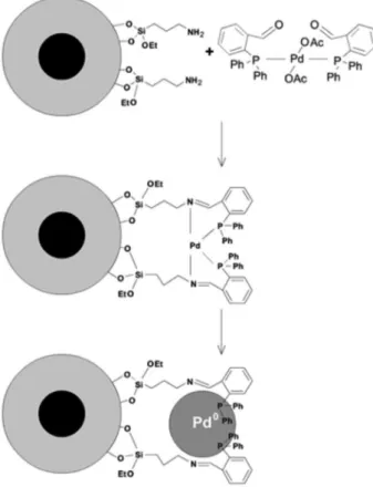
We synthesized a catalytic system based on Pd NPs stabilized by an iminophosphine ligand grafted on the support surface for C-C coupling reactions (Figure 5). The catalysts was prepared using an amino-functionalized support that was reacted with a complex containing free aldehyde groups [Pd(OAc)2(oPCHO)2] (oPCHO = 2-(diphenylphosphino)
benzaldehyde), which allowed the complex to be covalently attached to the support by means of an imine bond formation. The Pd-iminophosphine complex was thermally decomposed to form supported Pd NPs, while leaving uncoordinated phosphine groups covalently bound to the support, as confirmed by solid state NMR studies. The Pd NP-iminophosphine system was more efficient in the Suzuki coupling reaction than the catalyst prepared with the amine-functionalized support. The catalyst could be reused
in 10 successive reaction cycles before showing signs of deactivation, without addition of excess of phosphine.83
4.2 Rhodium, platinum and iridium catalysts
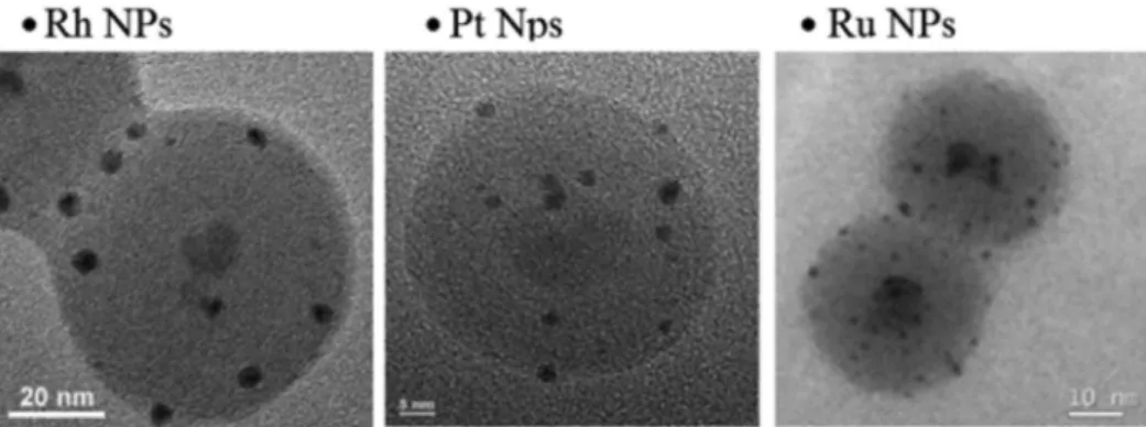
Our group extended the use of silica-coated magnetite with surfaces functionalized with amino groups, obtained by reaction of the silica surface with 3-aminopropyltriethoxysilane, to the synthesis of various magnetically recoverable metal NPs. In several examples Figure 4. Micrographs of palladium NPs supported on core-shell silica-coated magnetite prepared by microemulsion with surfaces functionalized with amine and ethylenediamine groups, and with non-functionalized surfaces. Reprinted with permission from reference 56 (copyright 2009 American Chemical Society).
studied, the amount of metal ions loaded on the support was always higher in the functionalized silica by at least 10 times the amount loaded on non-functionalized silica.74
This behavior was observed for Rh(III), Pt(II) and Ir(III) salts. The metallic precursors loaded on the silica-coated magnetic support previously modified with amine groups were reduced with hydrogen under mild conditions (typically 6 atm H2 and 75-100 °C), resulting in nearly
2-5 nm supported metal NPs (Figure 6). Magnetically recoverable rhodium NPs,54 platinum NPs55 and iridium
NPs84 were prepared.
The Rh NP catalyst is highly active with turnover
frequencies as high as 40000 and 1100 h–1 in the
hydrogenation of cyclohexene and benzene at 75 °C and 6 atm H2, respectively, and could be reused up to 20 times
in the hydrogenation of cyclohexene (180000 mol mol–1
Rh) and benzene (11550 mol mol–1 Rh) without metal
leaching to the organic phase (confirmed by ICP OES). This same catalyst has shown very interesting catalytic activities in the liquid hydrogenation of polycyclic aromatic hydrocarbons.57
The Pt NP catalyst is highly active in the hydrogenation of ketones, alkenes and arenes. The substrates were converted to the fully hydrogenated form, but partially hydrogenated products were also isolated by stopping the reaction at the time indicated by the hydrogen profile of the hydrogenation curve (e.g., ethylbenzene was isolated with 98.9% selectivity during hydrogenation of styrene). The catalyst could be reused for up to 14 successive reactions (15600 mol mol–1 Pt) without deactivation.
The Ir NP catalyst is highly active when compared to the literature with turnover frequencies as high as 6000 h–1 (hydrogenation of cyclohexene at 100 °C and
6 atm H2). The reaction could be repeated for up to six times
giving > 99% conversion and an accumulated turnover number of 12600 mol of substrate converted per mol of catalyst without catalyst deactivation.
4.3 Ruthenium catalysts
Magnetically recoverable Ru NPs were prepared by NaBH4 reduction of Ru
3+ loaded into a silica-coated
magnetic support previously modified with amine groups.53 The catalyst was found to be active in both
forms, Ru(III) and Ru(0), in the selective oxidation of alcohols and hydrogenation of alkenes, respectively. Aryl and alkyl alcohols were converted into aldehydes under mild conditions, with negligible metal leaching. If the metal was properly reduced, Ru(0) NPs were obtained (Figure 6), and the catalyst became active for hydrogenation reactions. A magnetically recoverable catalysts based on Ru(OH)x was prepared by impregnation of Ru3+ ions on
the silica-coated magnetic support previously modified with amine groups followed by treatment with sodium hydroxide to form ruthenium hydroxide species.85 The catalyst
was used in the selective aerobic oxidation of alcohols, including terpenes, to the corresponding aldehydes. Various carbonylic monoterpenoids important for fragrance and pharmaceutical industries could be obtained in good to excellent yields starting from biomass-based monoterpenic alcohols, such as isoborneol, perillyl alcohol, carveol and citronellol.
4.4 Nickel and cobalt catalysts
nickel oxide reduction back to the most active Ni(0) form. In this context, an organometallic approach has offered an excellent route for the synthesis of Ni NPs. The olefinic ligands of the organometallic precursor are reduced, and the naked atoms condense, producing metal NPs with clean and unoxidized metal surfaces. Our group has prepared a robust, oxidation-resistant and very active nickel catalyst by controlled decomposition of the organometallic precursor [bis(1,5-cyclooctadiene)nickel(0)], Ni(COD)2
over the silica-coated magnetite support.86 The sample is
mostly Ni(0) and only partial surface oxidation could be detected after storage in air (X-ray absorption near edge structure (XANES) and X-ray photoelectron spectroscopy (XPS) results), but the catalytic results indicate that these oxidized nickel species can be reduced back to the Ni(0) active catalyst under mild hydrogenation reaction conditions (1 bar of H2 and 75 °C), in contrast with NiO
bulk that is nonreactive under these conditions. The catalyst exhibited very promising activity in the hydrogenation of cyclohexene converting 4500 mol substrate per mole of catalyst (15 recycles without deactivation, TOF up to 1500 h-1) under the conditions studied (75 oC and 6 atm H
2).
Metal leaching was not detected in the products (inductively coupled plasma optical emission spectrometry, ICP OES, Ni < 0.01 ppm), demonstrating the efficiency of magnetic separation. For comparison, the widely used Raney nickel catalyst was tested in the hydrogenation of cyclohexene under similar conditions (0.33 mol% of Ni, 75 °C and 6 bar H2), but only 29% conversion was reached after 48 h of
reaction, which means that Raney Ni was also not activated in the reaction conditions. An important feature of the Ni catalyst prepared from the organometallic precursor is that it can be activated in situ in the hydrogenation reaction under very mild condition.
A magnetically recoverable cobalt catalyst was prepared as CoO NPs by impregnation of Co3+ salt in basic media
on silica-coated magnetic support previously modified with amine groups.87 The catalyst exhibited interesting
properties in the oxidation of cyclohexene, as for example, high selectivity to the allylic oxidation product. It was also observed that CoO is the most active species when compared to Co2+, Co
3O4 and Fe3O4 in the catalytic
conditions studied.
4.5 Gold catalysts
Magnetically recoverable Au NP catalysts were prepared by reduction of gold ions that were impregnated on silica-coated magnetic support previously modified with amine groups.58 The Au NPs were prepared by thermal reduction
in air and by hydrogen reduction at mild temperatures
of the gold species attached to the magnetic support. Interestingly, the mean particle size of the supported Au NPs was similar, ca. 5.9 nm, but the polydispersion of the nanoparticle size and the catalytic performance in oxidation of alcohols significantly changed. The catalyst reduced by hydrogen exhibited a narrow particle size distribution and was the most active in the oxidation of benzyl alcohol under milder conditions (100% conversion at 3 atm O2 compared
with only 10% conversion of the catalyst prepared by thermal reduction). Impregnation studies with gold ions have shown very low affinity of gold(III) ions to silica surfaces, and an enhanced interaction was favored by coordination of gold ions to amine groups grafted on the functionalized silica surfaces.88 Non-functionalized and
amine-functionalized silica supports were loaded with Au3+
precursor and the intermediate species were characterized by XANES. The non-functionalized solid was prepared by wetness impregnation in such a way that both solids contained the same amount of gold. The comparison of XANES spectra obtained from the material with and without functionalization, and the standards Au0 and Au3+,
have shown that the white line intensity of gold loaded on amine-functionalized silica decreased relative to the Au3+
standard, indicating a partial reduction of the gold ions. This behavior indicated a strong interaction between the amine groups and the gold ion thus causing a change in the coordination environment and oxidation state of the metal. The non-functionalized support has an intermediate white line intensity, which suggests a weak interaction with the oxygenated species on silica surfaces. After reduction of gold, the non-functionalized support contained only NPs that were not attached to the support, indicating the weak interaction with the silanol groups. In the case of amine-functionalized support, the NPs formed were exclusively deposited on the support.
All the NP-supported catalyst mentioned here could be isolated and recycled with the assistance of an external magnet, which greatly simplifies the workup procedure, and purification of products, minimizing the use of solvents, costly consumables, energy and time.
5. Final Remarks
applied in the recovery of high performance catalysts used in different reaction media, such as in reductions, oxidation, C−C coupling, to name a few reactions under study. Magnetic
separation is an environmentally friendly alternative for the separation and recovery of catalysts since it minimizes the use of solvents and auxiliary materials, operating time, catalysts loss (prevents mass loss and oxidation) and energy. The unique combination of superparamagnetic nanoparticles and catalytic active species (metal complexes, metal nanoparticles, enzymes, organocatalysts, etc.) opens the opportunity to solve a range of catalyst recovery problems to which no other filtration technique is easily applicable. Magnetic separation applied in biotechnology dated back to the 1970’s, but it has only received attention in the field of catalysis after 2005 (< 5 articles per year before 2004 increased to >50 articles per year in 2011 containing the words “magnetic* and separation and catalyst” in the Web of Science, accessed in September 16th, 2012). In
most of the examples in the literature, the advantages of using magnetic materials as supports has been applied for the separation of homogeneous catalysts and their applications in organic synthesis. Moreover, our group is not aware of the use of magnetic separation in industrial reactors for the recovery of “non-magnetic” active phases supported on magnetic solids. An interesting recent example in the scientific literature shows the design of a tubular reactor containing a rotating magnetic field which holds the nanoparticles containing the catalyst phase under stirring and suspended in a liquid column for continuous flow reactions.89 Synthesis scale up of superparamagnetic
supports and the design of reactors with magnetic separation in batch or continuous flow mode need more attention for further development in the field. Besides the development of magnetic supports, our group has been studying the stability of metal-support interactions, control of metal leaching, reaction conditions and methods of reducing metal precursors, and the functionalization of supports with different organic ligands as a strategy to improve the formation of supported metal nanoparticles with well-defined size and firmly attached to the support. Our research group has contributed to the training of personnel and generation of original contributions in the international literature in the area of magnetic nanomaterials and nanocatalysis.
Acknowledgments
The authors acknowledge financial support from FAPESP, CAPES, CNPq, and INCT-Catalise. We also thank the fruitful discussions with Prof. Dr. Renato F. Jardim (IF-USP) and the contribution of Dr. Patricia Busko Di Vitta
(Chemical Residues and Solvents Recovery Facility at IQ-USP).
Liane M. Rossi studied Chemical Engineering at the Federal University of Rio Grande do Sul (UFRGS, Brazil) and obtained her PhD in Chemistry at the Federal University of Santa Catarina (UFSC, Brazil) in 2001. After a two year postdoctoral stay at UFRGS and another postdoctoral stay year at the University of New Orleans (USA), in 2004, she joined the Institute of Chemistry at the University of São Paulo (USP, Brazil) where she is an Associate Professor (since 2010). Her research interests include novel approaches for the synthesis of supported metal nanoparticles with controlled sizes and morphologies for applications in the field of catalysis, and the development of magnetically recoverable catalysts to facilitate catalyst recovery and recycling in liquid phase reactions.
L u c a s L . R . Vo n o s t u d i e d Chemistry at the University of São Paulo (USP, Brazil), where he also obtained his MSc degree in Chemistry in 2010. He is currently a PhD student in the Prof. Rossi’s group in the Institute of Chemistry at USP. His current research interests include the development of magnetic materials as catalyst supports, the synthesis of supported metal nanoparticles and their application in catalysis.
Marco Aurélio Suller Garcia r e c e i v e d h i s B . S . d eg r e e i n Environmental Chemistry at the University of São Paulo (USP, Brazil) in 2010. He is currently a PhD student in the Prof. Rossi’s group in the Institute of Chemistry at USP. His current research interests include the development of supported catalysts for hydroformylation and oxidation reactions.
References
2. Jiles, D. C.; Introduction to Magnetism and Magnetic Materials, 2nd ed.; Chapman and Hall/CRC: London, England, 1998.
3. Morrish, A. H.; The Physical Principles of Magnetism; IEEE Press: New York, 2001.
4. Bean, C. P.; J. Appl. Phys. 1955, 26, 1381. 5. Brown, W. F.; Phys. Rev. 1963, 130, 1677.
6. Lu, A. H.; Salabas, E. L.; Schuth, F.; Angew. Chem., Int. Ed.
2007, 46, 1222.
7. Jeong, U.; Teng, X.; Wang, Y.; Yang, H.; Xia, Y.; Adv. Mater.
2007, 19, 33.
8. Park, J.; Joo, J.; Kwon, S. G.; Jang, Y.; Hyeon, T.; Angew. Chem., Int. Ed. 2007, 46, 4630.
9. Sun, S. H.; Zeng, H.; Robinson, D. B.; Raoux, S.; Rice, P. M.; Wang, S. X.; Li, G. X.; J. Am. Chem. Soc. 2004, 126, 273. 10. Sun, S. H.; Zeng, H.; J. Am. Chem. Soc. 2002, 124, 8204. 11. Park, J.; An, K. J.; Hwang, Y. S.; Park, J. G.; Noh, H. J.; Kim,
J. Y.; Park, J. H.; Hwang, N. M.; Hyeon, T.; Nat. Mater. 2004,
3, 891.
12. Yu, W. W.; Falkner, J. C.; Yavuz, C. T.; Colvin, V. L.; Chem. Commun. 2004, 2306.
13. Hyeon, T.; Lee, S. S.; Park, J.; Chung, Y.; Bin Na, H.; J. Am. Chem. Soc. 2001, 123, 12798.
14. Cornell, R. M.; Schwertmann, U.; The Iron Oxides: Structure, Properties, Reactions, Occurence and Uses; VCH: Weinheim, Germany, 1996.
15. Ziolo, R. F.; Giannelis, E. P.; Weinstein, B. A.; Ohoro, M. P.; Ganguly, B. N.; Mehrotra, V.; Russell, M. W.; Huffman, D. R.;
Science 1992, 257, 219.
16. Kodama, R. H.; J. Magn. Magn. Mater. 1999, 200, 359. 17. Frei, E. H.; Shtrikman, S.; Treves, D.; Phys. Rev. 1957, 106,
446.
18. Yavuz, C. T.; Prakash, A.; Mayo, J. T.; Colvin, V. L.; Chem. Eng. Sci. 2009, 64, 2510.
19. Safarik, I.; Safarikova, M.; J. Chromatogr., B 1999, 722, 33. 20. Whitesides, G. M.; Kazlauskas, R. J.; Josephson, L.; Trends
Biotechnol. 1983, 1, 144.
21. Heden, C. G.; Biotechnol. Bioeng. 1972, 173.
22. Robinson, P. J.; Dunnill, P.; Lilly, M. D.; Biotechnol. Bioeng.
1973, 15, 603.
23. Koehler, F. M.; Rossier, M.; Waelle, M.; Athanassiou, E. K.; Limbach, L. K.; Grass, R. N.; Gunther, D.; Stark, W. J.; Chem. Commun. 2009, 4862.
24. Liu, X. W.; Hu, Q. Y.; Fang, Z.; Zhang, X. J.; Zhang, B. B.;
Langmuir 2009, 25, 3.
25. Shin, S.; Jang, J.; Chem. Commun. 2007, 4230.
26. Shylesh, S.; Schunemann, V.; Thiel, W. R.; Angew. Chem., Int. Ed. 2010, 49, 3428.
27. Hatch, G. P.; Stelter, R. E.; J. Magn. Magn. Mater. 2001, 225, 262.
28. Polshettiwar, V.; Luque, R.; Fihri, A.; Zhu, H.; Bouhrara, M.; Bassett, J.-M.; Chem. Rev. 2011, 111, 3036.
29. Grass, R. N.; Athanassiou, E. K.; Stark, W. J.; Angew. Chem., Int. Ed. 2007, 46, 4909.
30. Jun, C. H.; Park, Y. J.; Yeon, Y. R.; Choi, J. R.; Lee, W. R.; Ko, S. J.; Cheon, J.; Chem. Commun. 2006, 1619.
31. Philipse, A. P.; Vanbruggen, M. P. B.; Pathmamanoharan, C.;
Langmuir 1994, 10, 92.
32. Lu, Y.; Yin, Y. D.; Mayers, B. T.; Xia, Y. N.; Nano Lett. 2002,
2, 183.
33. Yi, D. K.; Lee, S. S.; Papaefthymiou, G. C.; Ying, J. Y.; Chem. Mater. 2006, 18, 614.
34. Yi, D. K.; Selvan, S. T.; Lee, S. S.; Papaefthymiou, G. C.; Kundaliya, D.; Ying, J. Y.; J. Am. Chem. Soc. 2005, 127, 4990. 35. Im, S. H.; Herricks, T.; Lee, Y. T.; Xia, Y. N.; Chem. Phys. Lett.
2005, 401, 19.
36. Narita, A.; Naka, K.; Chujo, Y.; Colloids Surf., A 2009, 336, 46. 37. Ohmori, M.; Matijevic, E.; J. Colloid Interface Sci. 1992, 150,
594.
38. Ohmori, M.; Matijevic, E.; J. Colloid Interface Sci. 1993, 160, 288.
39. Zhang, M.; Cushing, B. L.; O’Connor, C. J.; Nanotechnology
2008, 19, 1.
40. Park, J. C.; Gilbert, D. A.; Liu, K.; Louie, A. Y.; J. Mater. Chem.
2012, 22, 8449.
41. Abramson, S.; Safraou, W.; Malezieux, B.; Dupuis, V.; Borensztajn, S.; Briot, E.; Bee, A.; J. Colloid Interface Sci.
2011, 364, 324.
42. Caruana, L.; Costa, A. L.; Cassani, M. C.; Rampazzo, E.; Prodi, L.; Zaccheroni, N.; Colloids Surf., A 2012, 410, 111. 43. Aliev, F. G.; Correa-Duarte, M. A.; Mamedov, A.; Ostrander, J.
W.; Giersig, M.; Liz-Marzan, L. M.; Kotov, N. A.; Adv. Mater.
1999, 11, 1006.
44. Hui, C.; Shen, C.; Tian, J.; Bao, L.; Ding, H.; Li, C.; Tian, Y.; Shi, X.; Gao, H.-J.; Nanoscale 2011, 3, 701.
45. Lee, J.; Lee, Y.; Youn, J. K.; Bin Na, H.; Yu, T.; Kim, H.; Lee, S.-M.; Koo, Y.-M.; Kwak, J. H.; Park, H. G.; Chang, H. N.; Hwang, M.; Park, J.-G.; Kim, J.; Hyeon, T.; Small 2008, 4, 143. 46. Li, C.; Ma, C.; Wang, F.; Xi, Z.; Wang, Z.; Deng, Y.; He, N.;
J. Nanosci. Nanotechnol. 2012, 12, 2964.
47. Lien, Y.-H.; Wu, T.-M.; J. Colloid Interface Sci. 2008, 326, 517. 48. Stober, W.; Fink, A.; Bohn, E.; J. Colloid Interface Sci. 1968,
26, 62.
49. Tada, D. B.; Vono, L. L. R.; Duarte, E. L.; Itri, R.; Kiyohara, P. K.; Baptista, M. S.; Rossi, L. M.; Langmuir 2007, 23, 8194. 50. Rossi, L. M.; Silva, F. P.; Vono, L. L. R.; Kiyohara, P. K.; Duarte, E. L.; Itri, R.; Landers, R.; Machado, G.; Green Chem. 2007,
9, 379.
51. Tartaj, P.; Serna, C. J.; J. Am. Chem. Soc. 2003, 125, 15754. 52. Yang, H. H.; Zhang, S. Q.; Chen, X. L.; Zhuang, Z. X.; Xu,
J. G.; Wang, X. R.; Anal. Chem. 2004, 76, 1316.
54. Jacinto, M. J.; Kiyohara, P. K.; Masunaga, S. H.; Jardim, R. F.; Rossi, L. M.; Appl. Catal., A 2008, 338, 52.
55. Jacinto, M. J.; Landers, R.; Rossi, L. M.; Catal. Commun. 2009,
10, 1971.
56. Rossi, L. M.; Nangoi, I. M.; Costa, N. J. S.; Inorg. Chem. 2009,
48, 4640.
57. Jacinto, M. J.; Santos, O.; Landers, R.; Kiyohara, P. K.; Rossi, L. M.; Appl. Catal., B 2009, 90, 688.
58. Oliveira, R. L.; Kiyohara, P. K.; Rossi, L. M.; Green Chem.
2010, 12, 144.
59. Landfester, K.; Ramirez, L. P.; J. Phys.: Condens. Matter 2003,
15, S1345.
60. Kim, D. K.; Mikhaylova, M.; Zhang, Y.; Muhammed, M.; Chem. Mater. 2003, 15, 1617.
61. Gupta, A. K.; Gupta, M.; Biomaterials 2005, 26, 3995. 62. Schaetz, A.; Grass, R. N.; Stark, W. J.; Reiser, O.; Chem.--Eur.
J. 2008, 14, 8262.
63. Wittmann, S.; Schaetz, A.; Grass, R. N.; Stark, W. J.; Reiser, O.;
Angew. Chem., Int. Ed. 2010, 49, 1867.
64. Teixeira, A. P. C.; Tristao, J. C.; Araujo, M. H.; Oliveira, L. C. A.; Moura, F. C. C.; Ardisson, J. D.; Amorim, C. C.; Lago, R. M.;
J. Braz. Chem. Soc. 2012, 23, 1579.
65. Alvarez, P. M.; Jaramillo, J.; Lopez-Pinero, F.; Plucinski, P. K.;
Appl. Catal., B 2010, 100, 338.
66. Ye, M. M.; Zorba, S.; He, L.; Hu, Y. X.; Maxwell, R. T.; Farah, C.; Zhang, Q. A.; Yin, Y. D.; J. Mater. Chem. 2010, 20, 7965. 67. He, Q.; Zhang, Z.; Xiong, J.; Xiong, Y.; Xiao, H.; Opt. Mater.
2008, 31, 380.
68. F i n ke , R . G . I n M e t a l N a n o p a r t i c l e s : S y n t h e s i s , Characterization and Applications; Feldheim, D. L.; Foss Jr., C. A., eds.; Marcel Dekker: New York, USA, 2002, p. 17-54. 69. Doyle, A. M.; Shaikhutdinov, S. K.; Jackson, S. D.; Freund, H. J.;
Angew. Chem., Int. Ed. 2003, 42, 5240.
70. Astruc, D.; Lu, F.; Aranzaes, J. R.; Angew. Chem., Int. Ed. 2005,
44, 7852.
71. Dahl, J. A.; Maddux, B. L. S.; Hutchison, J. E.; Chem. Rev.
2007, 107, 2228.
72. Mevellec, V.; Roucoux, A.; Ramirez, E.; Philippot, K.; Chaudret, B.; Adv. Synth. Catal. 2004, 346, 72.
73. Roucoux, A.; Schulz, J.; Patin, H.; Adv. Synth. Catal. 2003, 345, 222.
74. Vasylyev, M. V.; Maayan, G.; Hovav, Y.; Haimov, A.; Neumann, R.; Org. Lett. 2006, 8, 5445.
75. Dupont, J.; Fonseca, G. S.; Umpierre, A. P.; Fichtner, P. F. P.; Teixeira, S. R.; J. Am. Chem. Soc. 2002, 124, 4228.
76. Geldbach, T. J.; Zhao, D. B.; Castillo, N. C.; Laurenczy, G.; Weyershausen, B.; Dyson, P. J.; J. Am. Chem. Soc. 2006, 128, 9773.
77. Migowski, P.; Dupont, J.; Chem.--Eur. J. 2007, 13, 32. 78. Park, I. S.; Kwon, M. S.; Kim, N.; Lee, J. S.; Kang, K. Y.;
Park, J.; Chem. Commun. 2005, 5667.
79. Pélisson, C.-H.; Vono, L. L. R.; Hubert, C.; Denicourt-Nowicki, A.; Rossi, L. M.; Roucoux, A.; Catal. Today 2012, 183, 124. 80. Costa, N. J. S.; Rossi, L. M.; Nanoscale 2012, 4, 5826. 81. Rossi, L. M.; Vono, L. L. R.; Silva, F. P.; Kiyohara, P. K.; Duarte,
E. L.; Matos, J. R.; Appl. Catal., A 2007, 330, 139.
82. Nangoi, I. M.; Kiyohara, P. K.; Rossi, L. M.; Appl. Catal., B
2010, 100, 42.
83. Costa, N. J. S.; Kiyohara, P. K.; Monteiro, A. L.; Coppel, Y.; Philippot, K.; Rossi, L. M.; J. Catal. 2010, 276, 382. 84. Jacinto, M. J.; Silva, F. P.; Kiyohara, P. K.; Landers, R.; Rossi,
L. M.; ChemCatChem 2012, 4, 698.
85. Costa, V. V.; Jacinto, M. J.; Rossi, L. M.; Landers, R.; Gusevskaya, E. V.; J. Catal. 2011, 282, 209.
86. Costa, N. J. S.; Jardim, R. F.; Masunaga, S. H.; Zanchet, D.; Landers, R.; Rossi, L. M.; ACS Catal. 2012, 2, 925.
87. Silva, F. P.; Jacinto, M. J.; Landers, R.; Rossi, L. M.; Catal. Lett. 2011, 141, 432.
88. Oliveira, R. L.; Zanchet, D.; Kiyohara, P. K.; Rossi, L. M.;
Chem.--Eur. J. 2011, 17, 4626.
89. Schaetz, A.; Grass, R. N.; Kainz, Q.; Stark, W. J.; Reiser, O.;
Chem. Mater. 2010, 22, 305.
Submitted: November 3, 2012 Published online: December 14, 2012