ABSTRACT
Effect of cant ilever lengt h and alloy fram ework
on t he st ress dist ribut ion in peri- im plant area
RI FDQWLOHYHUHG LPSODQWVXSSRUWHG ¿[HG SDUWLDO
dent ures
Valdey SUEDAM1, Rafael Tobias MORETTI NETO2, Edson Antonio Capello SOUSA, José Henrique RUBO4
1- Universidade do Sagrado Coração, Faculdade de Odontologia, Bauru, SP, Brazil.
2- Universidade Federal de Alfenas, Faculdade de Odontologia, Departamento de Clínica e Cirurgia, Alfenas, MG, Brazil. 3- Universidade Estadual Paulista, Faculdade de Engenharia, Departamento de Engenharia Mecânica, Bauru, SP, Brazil. 4- Universidade de São Paulo, Faculdade de Odontologia de Bauru, Departamento de Prótese, Bauru, SP, Brazil.
Corresponding address: José Henrique Rubo - Al. Octávio Pinheiro Brisola, 9-75 - Bauru - SP - Brazil - 17012-901 - Phone/Fax: +81 14 3235 8277 - E-mail: [email protected]
6XEPLWWHG-XO\0RGL¿FDWLRQ2FWREHU$FFHSWHG1RYHPEHU
B
ecause m any m echanical variables are present in t he oral cavit y, t he proper load t ransfer bet ween t he prost hesis and t he bone is im port ant for t reat m ent planning and for t heORQJHYLW\RIWKHLPSODQWVXSSRUWHG¿[HGSDUWLDOGHQWXUH2EMHFWLYHV7RYHULI\WKHVWUHVV JHQHUDWHGRQWKHSHULLPSODQWDUHDRIFDQWLOHYHUHGLPSODQWVXSSRUWHG¿[HGSDUWLDOGHQWXUHV
and t he pot ent ial effect s of such variable. Mat erial and Met hods: A U- shaped polyuret hane m odel sim ulat ing t he m andibular bone cont aining t wo im plant s ( Ø 3.75 m m ) was used. Six groups were form ed according t o t he alloy’s fram ework ( CoCr or PdAg) and t he point of load applicat ion ( 5 m m , 10 m m and 15 m m of cant ilever arm ) . A 300 N load was applied in pre- det erm ined reference point s. The t ension generat ed on t he m esial, lingual, dist al and buccal sides of t he peri- im plant regions was assessed using st rain gauges. Result s:
7ZRZD\$129$DQG7XNH\VWDWLVWLFDOWHVWVZHUHDSSOLHGVKRZLQJVLJQL¿FDQWGLIIHUHQFHV
( p< 0.05) bet ween t he groups. Pearson correlat ion t est ( p< 0.05) was applied showing posit ive correlat ions bet ween t he increase of t he cant ilever arm and t he deform at ion of t he peri- im plant area. Conclusions: This report dem onst rat ed t he CoCr alloy shows larger com pression values com pared t o t he PdAg alloy for t he sam e dist ances of cant ilever. The
SRLQWRIORDGDSSOLFDWLRQLQÀXHQFHVWKHGHIRUPDWLRQRQWKHSHULLPSODQWDUHDLQFUHDVLQJ
in accordance wit h t he increase of t he lever arm .
Ke yw or ds: I m plant- support ed dent al prost hesis. Dent al im plant s. I n vit ro t echniques. Mechanical st ress.
I N TROD UCTI ON
,Q¿[HGLPSODQWVXSSRUWHGSURVWKHVLVWKHORDG DSSOLHGWRWKHRFFOXVDOVXUIDFHRIDUWL¿FLDOWHHWKLV
t ransm it t ed along t he fram ework and t he abut m ent t o t he surrounding bone where m ost part of it is absorbed at t he expenses of bone deform at ion.
According t o Frost8 ( 2004) , t he bone react s t o
forces according t o t he int ensit y of t he t ension. Bone responses t o t ension could t hen be divided in four int ervals or w indow s: 1: The acut e disuse w indow wit h t ensions below 50 m e ( m icrom et er) ,
result ing in bone loss because of an increase in t he rem odeling process; 2: The adapt at ion w indow
wit h t ensions bet ween 50 m e and 1500 m e where phy siological adapt at ion occu r s w it h a balan ce bet w een r esor pt ion and for m at ion; 3: The m ild
overload w indow wit h t ensions bet ween 1500 m e
and 4000 m e and where an increase in t he m odeling pr ocess occur s, im pr ov ing bone st r uct ur e; and
4: The pat hologic overload w indow charact erized
E\WHQVLRQVDERYHİZKHQERQHUHVRUSWLRQ
t akes place.
According t o Chang, et al.6 ( 2013) , knowledge
w h en t h e den t al im plan t is ex cessiv ely loaded is lim it ed and t he level of evidence is poor. Wit h
DQLPDO H[SHULPHQWDO VWXGLHV VKRZLQJ FRQÀLFWLQJ
r esult s, it is unclear w het her occlusal ov er load m ig h t cau se m ar g in al b on e loss or t ot al loss of osseoin t egr at ion t o alr eady osseoin t egr at ed dent al im plant s when t he applied load exceeds t he biologically- accept able lim it . This biological lim it is also unknown. Furt herm ore, higher rem odeling act ivit y of t he peri- im plant bone is found around im plant s subj ect ed t o high loading forces. The st rain values t hat can act ually cause biological changes are not com plet ely known30. Cert ain horm ones and
biochem ical agent s can also change t he syst em , causing changes t o t he lim it s of t olerance8.
7KH LPSODQWVXSSRUWHG ¿[HG SURVWKHVLV ZLWK
d ist ally ex t en d ed lev er ar m s p r esen t p ecu liar charact er ist ics of for ce dist r ibut ion since all t he force applied in t he post erior region of t he cant ilever is t ransm it t ed t o t he im plant s and consequent ly t o t he adj acent bone297KH¿QGLQJVRIRWKHUVWXGLHV
such as Benzing, et al.5 ( 1995) and Lew inst ein,
et al.1 6 ( 1 9 9 5 ) , dem on st r at e t h at t h e in cr ease
of t h e can t ilev er ar m pr om ot es an in cr ease in st ress concent rat ion around t he t erm inal im plant . A can t ilev er ar m of 1 0 - 2 0 m m is con sid er ed accept able depending on t he qualit y of t he bone where im plant s are placed14,20,21,27.
According t o Benzing, et al.5 ( 1995) , t he load
applicat ion on t he cant ilever arm of an im plant-su p p o r t e d f r a m e w o r k p r o d u ce s d e f o r m a t i o n e n e r g y i n t h e sy st e m t h a t ca u se s b e n d i n g , depending on t he differences of elast ic m odulus of several m at erials and com ponent s. St udies have dem onst rat ed t hat t he pat t ern of st ress dist ribut ion am ong abut m ent s depends, am ong ot her fact ors, on t he alloy t ype used for fram ework2,10,11. According
t o som e aut hors, Benzing, et al.5*HQJHW
al.9 ( 2001) and Duyck & Naert7 ( 2002) , a m at erial ZLWKVPDOOHUHODVWLFPRGXOXVRIIHUVVPDOOHUÀH[XUH
resist ance; fram eworks m ade wit h rigid basic alloys suffer less deform at ion, being less prone t o fat igue and, consequent ly, not over loading t he scr ew s. Som e clinical12 and laborat ory1,13,23,26,29 st udies have
used CoCr alloys for im plant- support ed prost heses fram eworks.
The clinical success of osseoint egrat ed im plant s
DUHODUJHO\LQÀXHQFHGE\WKHPDQQHUPHFKDQLFDO
st resses are t ransferred from t he im plant t o t he surrounding bone wit hout generat ing forces of a m agnit ude t hat would j eopardize t he longevit y of im plant s and prost heses25. The force applied on t he FDQWLOHYHUHGLPSODQWVXSSRUWHG¿[HGSURVWKHVHVLV
t ransm it t ed t o t he peri- im plant area. However, t he m agnit udes of t he result ant st resses, considering t he elast icit y of t he bone, ar e under est im at ed. The aim of t his in vit r o st udy was t o verify t he m echanical st ress generat ed on t he peri- im plant
bone of an im plant prost hodont ic syst em when: ( 1) a load is applied at different cant ilever lengt hs and ( 2) alloys of different elast ic m odulus ( E) are used t o fabricat e t he fram ework.
M ATERI AL AN D M ETH OD S
A “ U” shaped polyuret hane m odel ( PU, Axson – Cergy, St . Ouen l’Aum ône, France) wit h t he following dim ensions: 100 m m in lengt h, 13 m m in widt h, 19 m m in height , 46 m m in int ernal diam et er, and 59 m m in ext ernal diam et er was used t o sim ulat e t he m andibular bone18,19. Tw o ex t er nal hex agon
Brånem ark Syst em®0N,,,*URRY1REHO%LRFDUH ±*|WHERUJ9lVWUD*|WDODQG6ZHGHQLPSODQWVRI
3.75 m m in diam et er and 13 m m in lengt h were em bedded in t h e m odel du r in g poly u r et h an e’s liqu id pou r in g in a m at r ix . Af t er poly u r et h an e hardening, t wo m ult i- unit abut m ent s ( Nobel Biocare
±*|WHERUJ9lVWUD*|WDODQG6ZHGHQRIPPLQ
lengt h were m anually screwed int o t he im plant s. A previously calibrat ed elect ronic t orque cont roller
GHYLFH1REHO%LRFDUH7RUTXH&RQWUROOHUl*|WHERUJ 9lVWUD*|WDODQG6ZHGHQZDVXVHGWRWLJKWHQWKH
abut m ent screws t o 20 Ncm t orque.
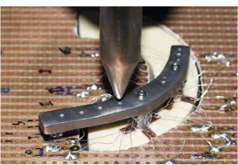
(LJKWVWUDLQJDJHV.)*&6WUDLQ *DJHV ± .\RZD (OHFWURQLF ,QVWUXPHQWV &R
Lt d., Tok y o, Honshu, Japan) w er e bonded w it h cyanoacrylat e on t he surface of t he polyuret hane m odel on t he dist al ( D) , lingual ( L) , m esial ( M) , and buccal ( B) sides of im plant 1 ( dist al) and im plant 2 ( m esial) , as can be seen in Figur e 1 . St rain gauges are able t o m easure t he t ension suffered by an obj ect or st ruct ure wit h which it is in close
FRQWDFW7KHWHQVLRQİUHSUHVHQWVWKHDPRXQWRI
deform at ion of a body when subm it t ed t o a given force t hat can be t ensile ( + ) or com pressive ( - ) .
The st rain gauges w er e connect ed t o a dat a a cq u i si t i o n d e v i ce ( NI cD AQ- 9 1 7 2 – Na t i o n a l I nst rum ent s Corp., Aust in, Texas, USA) t hat sent a signal t o a LabVI EW 8.1 program for Windows ( Nat ional I nst rum ent s Corp., Aust in, Texas, USA) inst alled in a com put er were input s from t he eight st rain gauges were analyzed.
Tw o f r am ew or k s sim u lat in g a can t ilev er ed
LPSODQWVXSSRUWHG ¿[HG SDUWLDO GHQWXUHV PDGH
fram ework pat t erns were cast in one piece, one in cobalt- chrom ium alloy ( Rexillium® N.B.F. – Jeneric®/
Pent ron® I ncorporat ed, Wallingford, Connect icut ,
USA) cast on cobalt - ch r om iu m abu t m en t s an d one in palladium - silver alloy ( Pors- on 4 – Degussa S.A., São Paulo, SP, Brazil) cast on palladium - silver abut m ent s. To allow t he correct posit ioning of t he loading applicat ion point , a dim ple was m ade on t he upper side of t he fram ework at 5 m m , 10 m m and 15 m m dist al t o t he cent er of t he t erm inal abut m ent .
The fram eworks were posit ioned in t he PU m odel abut m ent s and t est ed m anually. As observed, only fram ew orks t hat adapt ed w ell t o t he abut m ent s w er e t o b e a p p r ov ed f o r t h e t est s. Th e t w o fram eworks m et t his crit erion and t herefore t here was no need t o repeat t he cast s. Thus, t it anium scr e w s w e r e t i g h t e n e d t o 1 0 Ncm u si n g a n elect ronic t orque cont roller ( Nobel Biocare Torque
&RQWUROOHUl*|WHERUJ9lVWUD*|WDODQG6ZHGHQ
The PU m odel was adapt ed and st abilized in a cylindrical st eel base. The use of t his rigid m et allic base aim ed at not int erfering wit h t he deform at ion of t he PU m odel and not absorbing t he load applied during t he t est s. Six t est groups were form ed ( CoCr-5 m m , Pd Ag - CoCr-5 m m , Co Cr - 1 0 m m , Pd Ag - 1 0 m m , CoCr- 15m m and PdAg- 15m m ) , according t o t he alloy fram ework and t o t he point of load applicat ion.
Test specim ens were t aken t o a Universal Test ing Machine ( m odel K- 2000 MP – Krat os Equipam ent os I ndust riais Lt da., São Paulo, SP, Brazil) and baseline
UHDGLQJVRIWKHDEVROXWHVSHFL¿FGHIRUPDWLRQYDOXHV
developed on each st rain gauge were carried out prior t o t he load applicat ion ( reading precision of order 1X10- 6) . Before init iat ing t he readings on t he
defor m at ion caused by loading t he fram ew or k s, t he out put of t he m easur ing syst em was set t o zero t o separat e from t he deform at ion caused by
abut m ent / prost het ic screw t ight ening. A round st eel
SRLQWZDV¿[HGWRWKHORDGFHOODQGDGMXVWHGWRWKH
pre- det erm ined reference point in t he fram ework ( Figure 1) . Thus, t he t est ing m achine was set t o com pr ession at a cr oss- head speed of 0.5 m m / m in unt il it reached 300 N and st opped for one m inut e. The 300 N load was used t o run t he t est according t o t he m axim al occlusal bit e force values found by Akça, et al.3 ( 2006) for im plant- support ed
prost heses in opposit ion t o nat ural t eet h.
Deform at ion readings were t aken at each one of t he eight st rain gauges for t he durat ion of load applicat ion and 1 m inut e aft er load st abilizat ion. Only t he last 30 values of deform at ion were t aken int o account t o ensure t he m axim um and st able levels of deform at ion were recorded for each sit e. Load applicat ion was repeat ed 5 t im es t o calculat e t he m ean and t he st andard deviat ion.
The t wo- way ANOVA st at ist ical t est was applied
ZLWKWKH¿UVWYDULDEOHEHLQJWKHW\SHRIDOOR\&R&U
and PdAg) and t he second variable being t he
peri-LPSODQWUHJLRQ'/0DQG%ZKLFKFRQ¿UPHG WKHSUHVHQFHRIVWDWLVWLFDOO\VLJQL¿FDQWGLIIHUHQFHV
The Tukey t est w as applied t o com par e gr oups regarding t he effect of t wo t ypes of alloy. There
ZDV D VWDWLVWLFDOO\ VLJQL¿FDQW GLIIHUHQFH LQ HDFK
peri- im plant region ( p< 0.05) for t he force applied at t he 5 m m cant ilever ( D1, M1, B1, D2 and B2) , t he 10 m m cant ilever ( D1, L1, M1, B1, D2, L2 and M2) and t he 15 m m cant ilever ( D1, L1, M1, B1, D2, L2 and M2) . The Pearson correlat ion t est was applied t o correlat e t he dist ance of load applicat ion on t he cant ilever and t he values of deform at ion in each peri- im plant region.
RESULTS
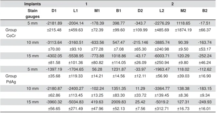
7KH¿QDOPHDQGHIRUPDWLRQDQGWKHVWDQGDUG
deviat ion values in each st rain gauge are t he result of 150 deform at ion readings. The num erical values obt ained are expressed as t ension ( posit ive values) and com pression ( negat ive values) , as seen in Table 1 and represent ed in Figure 2.
Wit h t he load applied on t he cant ilever for all six groups, t he m ost relevant result s of com pression occurred on t he dist al ( D1) and lingual ( L1) sides of im plant I ( dist al) , and on t he lingual ( L2) side of im plant 2 ( m esial) . Tension occurred on t he buccal ( B1) side of im plant I .
According t o Suedam , et al.29 ( 2009) , we can
not sum t he deform at ion suffered in every peri-im plant region of each peri-im plant and consider t his value as deform at ion of t he ent iret y because each
com ponent of t he sy st em pr ost hesis/ abut m ent / im plant / bone can be found under various condit ions of adapt at ion and load. As a result , a quant it at ive and qualit at ive evaluat ion of t he result s based on t he st at ist ical t est s becom es necessary, which give us a biom echanical behav ior v iew of t he ent ir e syst em involved wit h, and not only of t he st rain gauges or of t he peri- im plant regions individually.
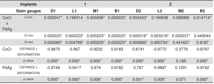
Th e r e s u l t s o f t h e Tu k e y t e s t ( Ta b l e 2 ) dem onst rat ed t he differ ence in t he fram ew or k ’s e l a st i c m o d u l u s i n f l u e n ce d t h e i n t e n si t y o f deform at ion occurred in t he peri- im plant region, as can be not ed in Table 1 and in Figure 2. The Pearson correlat ion t est showed posit ive correlat ion ( Table 2) .
Implants 1 2
Stain gauges
D1 L1 M1 B1 D2 L2 M2 B2
5 mm -2181.89 -2004.14 -178.39 398.77 -343.7 -2276.29 1118.65 -17.51
Group CoCr
±215.48 ±459.63 ±72.39 ±99.60 ±109.99 ±485.69 ±1874.19 ±66.37
10 mm -3113.64 -3160.51 -633.56 547.47 -215.146 -3885.74 90.39 -163.74
±70.00 ±93.10 ±77.28 ±7.08 ±65.30 ±240.98 ±9.50 ±53.17
15 mm -4302.05 -5538.95 -773.88 1018.86 -43.17 -6003.71 120.29 -252.24
±81.58 ±101.36 ±80.82 ±114.05 ±26.09 ±250.94 ±9.80 ±46.24
5 mm -1397.19 -1704.65 56.28 1231.87 -33.97 -1963.47 118.02 -112.62
Group PdAg
±35.68 ±119.33 ±14.21 ±14.56 ±12.11 ±56.90 ±39.03 ±16.90
10 mm -2180.87 -2400.27 -102.24 1351.35 11.29 -3364.77 138.38 -183.15
±62.86 ±113.45 ±13.25 ±83.30 ±33.72 ±139.45 ±8.36 ±9.34
15 mm -3960.32 -5034.83 419.63 2009.83 25.42 -5019.2 127.31 -249.93
±56.65 ±271.49 ±47.96 ±52.13 ±7.56 ±312.71 ±16.73 ±16.01
Table 1- Final mean and standard deviation of deformation values for each strain gauge with CoCr and PdAg alloys framework in tree conditions of load application (in Pܭ
D I SCUSSI ON
Knowledge on t he am ount of m echanical st ress generat ed in t he peri- im plant area when load is applied along t he cant ilever arm is essent ial for t he planning, execut ion and longevit y of t he t reat m ent wit h im plant- support ed prost heses.
Th i s s t u d y s h o w e d t h e p a t t e r n o f b o n e deform at ion generat ed by applying a st at ic force
of 300 N varied according t o: 1- The posit ion where t he st rain gages were locat ed on t he peri- im plant region ( D1, L1, M1, B1, D2, L2, M2 and B2) ; 2- The point of load applicat ion ( wit h 5 m m , 10 m m and 15 m m cant ilevers) ; 3- I m plant posit ion relat ive t o load applicat ion ( I 1 and I 2) ; 4- Type of alloy used for m aking fram eworks ( CoCr and PdAg) .
For all st udied groups t he behavior was singular, wit h t ension forces present in a larger degree in
Implants 1 2
Stain gauges D1 L1 M1 B1 D2 L2 M2 B2
CoCr x PdAg
5 mm 0.000247* 0.196314 0.000296* 0.000223* 0.000433* 0.190638 0.266985 0.014714*
10 mm 0.000223* 0.000223* 0.000223* 0.000223* 0.000318* 0.003219* 0.000237* 0.445044
15 mm 0.000260* 0.004769* 0.000223* 0.000223* 0.000660* 0.000754* 0.441627 0.9187
CoCr DISTANCE x
DEFORMATION
-0.9875 -0.967 -0.9232 0.9183 0.8741 -0.9772 -0.3776 -0.8797
p value 0.000* 0.000* 0.000* 0.000* 0.000* 0.000* 0.165 0.000*
PdAg DISTANCE x
DEFORMATION
-0.9748 -0.9417 0.674 0.9182 0.767 -0.9887 0.1591 -0.9742
p value 0.000* 0.000* 0.006* 0.000* 0.001* 0.000* 0.571 0.000*
VWDWLVWLFDOO\VLJQL¿FDQWGLIIHUHQFHIRUS
Table 2- Tukey test for comparisons between groups and Pearson correlation test (distance X deformation) for each group
t he st rain gauge locat ed at t he buccal region ( B1) of im plant 1, and com pressive forces present in a larger degree in st rain gauges at t he dist al and lingual region ( D1, L1) of im plant 1. This behavior can be due t o t he curved shape of t he fram ework, where t he result ing force t ends t o rot at e t he whole syst em t o t he dist al and buccal sides.
The m ean and st andard deviat ion was calculat ed
DIWHU¿YHORDGDSSOLFDWLRQVIRUHDFKJURXSUHVXOWRI
150 part ial m ean. Aft er each load applicat ion t he m echanical behavior of t he each com ponent of t he syst em prost hesis/ abut m ent / im plant / bone suffered deform at ion under st ress. This condit ion, associat ed
WRGLIIHUHQWGHJUHHVRI¿WDPRQJFRPSRQHQWVFDQ
be a possible cause of t he high values of st andard deviat ions found in t his st udy.
A c c o r d i n g t o d a t a f r o m o t h e r experim ent s4,5,13,21,23,28,29 in cant ilevered prost heses,
t he m ost dist al im plant s represent t he fulcrum and, t her efor e, ar e subj ect ed t o com pr ession for ces while int erm ediary abut m ent s suffer t ension. I n t his st udy, t he peri- im plant regions were divided in four ( D, L, M and B) allowing t he observat ion t hat t he dist al and lingual sides of t he m ost dist al im plant ( I 1) were subj ect t o higher values of com pression f or ces an d t h at t h ese v alu es in cr eased as t h e
FDQWLOHYHU LQFUHDVHG DV YHUL¿HG E\ WKH 3HDUVRQ
correlat ion t est ( Table 2) .
Th e n u m er ical v alu es ex p r essed in t en sion and com pr ession for bot h alloy s ar e t he r esult of fram ew or k behav ior due t o load applicat ion,
ZKHUH WKH DOOR\ HODVWLF PRGXOXV LQÀXHQFHV WKH
t ype of deform at ion and consequent ly t he t ension t r an sm it t ed t o t h e bon e2 , 1 0 , 1 1 , 1 3 , 1 7 , 2 9. Becau se of
t he lower elast ic m odulus of t he palladium - silver alloy com p ar ed t o t h e cob alt - ch r om iu m alloy,
DQGFRQVHTXHQWO\IRUSUHVHQWLQJDVPDOOHUÀH[LRQ
resist ance, t he result s expressed in Table 1, and in Figure 2 dem onst rat ed t hat when t he load was applied t o t he CoCr alloy groups, larger com pression v alu es w er e r ecor ded com par ed t o PdAg alloy g r ou p s, f or t h e sam e d ist an ces of can t ilev er. According t o Rubo & Souza23 ( 2009) and Suedam ,
et al.2 9 ( 2 0 0 9 ) , t h e Pd Ag alloy d ef lect s m or e,
absorbing part of t he load applied t o t he cant ilever r esult ing com pr ession for ces of low er int ensit y being t ransm it t ed t o t he surrounding bone. On t he
RWKHUKDQGEHFDXVHRILWVJUHDWHUGHÀHFWLRQZKHQ
com pared t o CoCr alloy, t he PdAg alloy present ed t he largest values of t ension on t he buccal side of
LPSODQW,DVFRQ¿UPHGE\WKH7XNH\WHVW
Th e load is t r an sm it t ed t o t h e su r r ou n din g bone where t he m ost part of it is absorbed at t he expense of deform at ion in bone st ruct ure, which is t he less rigid st ruct ure in t he syst em . Physiologic levels of t ension serve also t he purpose of bone rem odeling. This m echanism would help m aint ain
ERQHVWUXFWXUDOLQWHJULW\LQGH¿QLWHO\22. Nevert heless,
m echanical overload can lead t o biological failure24.
Wh en a pat h ological ov er load is applied t o an osseoin t eg r at ed im p lan t , t en sion ex ceed s t h e physiological t hreshold t olerat ed by t he bone and m icr o fract ur es m ay occur at t he im plant - bone int erface. Repeat ed overload can lead t o fat igue failure of t he im plant- bone int erface, reducing peri-im plant bone densit y and leading t o t he form at ion of bone defect s such as crat er s. The pat hologic overload window of Frost ’s Theory represent s t his sit uat ion, w hen bone under goes t ensions above
İEHLQJSURQHWRUHVRUSWLRQ,WLVLPSRUWDQW WR QRWH WKDW LQÀDPHG SHULLPSODQW WLVVXH UHDFWV
different ly t o occlusal overload prom ot ing increased bone resorpt ion, as dem onst rat ed by Kozlovsky, et al.15 ( 2007) .
Th e m easu r e of t en sion g en er at ed in p er i-im plant area gave us t he possibilit y of correlat ing t hese values wit h t he bone rem odeling t heory8 in
an at t em pt t o clarify t he biological process t hat t ak es place in t h at ar ea, con sider in g an ideal clinical condit ion. According t o t he polyuret hane m od el v alid at ion st u d ies m ad e b y Mor et t i, et al.19 ( 2011) and Miyashir o, et al.18 ( 2011) , t he
hom ogeneit y of polyuret hane ( PU) could favor it s use in biom echanical st udies of force dist ribut ion on im plant support ed prost heses, aim ed at est ablishing correlat ions bet ween st rains generat ed in t he peri-im plant region and physiological st rains as proposed by Frost ’s Theory.
Nev er t h eless, it is k n ow n t h at con sider able differences exist bet ween t his st udy and clinically int egrat ed im plant s. Alt hough poly ur et hane can pr esen t sim ilar elast ic m odu lu s t o bon e, ot h er
IHDWXUHVVXFKDVDQLVRWURS\DUHGLI¿FXOWWRPLPLF
This st udy does not claim t hat t he st rains found in t h e p oly u r et h an e m od el m at ch es p r ecisely t o t h e in - v iv o sit u at ion b u t ack n ow led g es t h e biom echanical process of load t ransm ission in an at t em pt t o underst and how bone t issue processes t hese t ransm it t ed loads.
A st r a i n d i a g r a m w a s u se d a s a g r a p h i c r e p r e se n t a t i o n o f t h e d e f o r m a t i o n r e a d i n g s generat ed on each side of t he peri- im plant region.
7KLVGLDJUDPFRQVLVWVRIDFLUFXODU¿JXUHLQDWDUJHW
shape w it h scales of 0 m e t o 7000 m e, w her e readings of deform at ions generat ed on t he dist al, lingual, m esial and buccal sides of each im plant s of t he groups CoCr- 15 m m and PdAg- 15 m m are visualized ( Figure 3) . I n t hese diagram s, t ensions
DERYH WR İ FDQ EH VHHQ IRU WKH &R&U
m m group ( D1= - 4302.05 m e, L1= - 5538.95 m e) ; t he sam e occurring wit h t he PdAg- 15 m m group ( D1= - 3960.32 m e and L1= - 5034.83 m e) . Based on t he lit erat ure, t hese result s have shown t he t wo groups present ed peri- im plant regions wit hin t he pat hologic overload window, being prone t o bone
arm s sm aller t han 15 m m should be considered during t he t reat m ent planning of t he m andibular
LPSODQWVXSSRUWHG¿[HGSDUWLDOGHQWXUHV
CON CLUSI ON S
Under t he lim it ed condit ions of t his in vit ro st udy, t he following conclusions were drawn: ( 1) The point
RIORDGDSSOLFDWLRQWRWKHFDQWLOHYHUDUPLQÀXHQFHG
t h e d ef or m at i on of t h e p er i - i m p l an t r eg i on s; ( 2 ) Th e t y p e of alloy u sed f or f ab r icat in g t h e
IUDPHZRUNLQÀXHQFHGWKHELRPHFKDQLFDOEHKDYLRU
and t he deform at ions of t he peri- im plant regions; ( 3) Cant ilever arm s sm aller t han 15 m m m ust be
FRQVLGHUHGIRUPDQGLEXODULPSODQWVXSSRUWHG¿[HG
part ial dent ures.
ACKN OW LED GEM EN TS
7KLVVWXG\ZDV¿QDQFLDOO\VXSSRUWHGE\&$3(6 &RRUGLQDWLRQ RI +LJKHU (GXFDWLRQ DQG *UDGXDWH
Tr a i n i n g ) a n d FAPESP ( Sã o Pa u l o Re se a r ch Foundat ion) grant s 99/ 01402- 6 and 05/ 56182- 3.
REFEREN CES
1- Abduo J, Bennani V, Lyons, K, Waddell N, Swain M. A novel in vit roDSSURDFKWRDVVHVVWKH¿WRILPSODQWIUDPHZRUNV&OLQO2UDO I m plant s Res. 2011; 22: 658- 63.
2 - Ak ça K, Çer eli MC, I plik çioglu H. A com par ison of t hr
ee-GLPHQVLRQDO ¿QLWH HOHPHQW VWUHVV DQDO\VLV ZLWKin v it r o st rain g au g e m easu r em en t s o n d en t al i m p l an t s. I n t J Pr o st h o d . 2002; 15: 115- 21.
$NoD.8\VDO6dHKUHOL0&,PSODQWWRRWKVXSSRUWHG¿[HG
par t ial pr ost heses: cor r elat ions bet w een in v iv o occlusal bit e for ces and m ar ginal bone r eact ions. Clin Oral I m plant s Res. 2006; 17: 331- 6.
4- Assif D, Marshak B, Horowit z A. Analysis of load t ransfer and
VWUHVVGLVWULEXWLRQE\DQLPSODQWVXSSRUWHG¿[HGSDUWLDOGHQWXUH
J Prost het Dent . 1996; 75: 285- 91.
%HQ]LQJ85*DOO+:HEHU+%LRPHFKDQLFDODVSHFWVRIWZR
different im plant- prost het ic concept s for edent ulous m axillae. I nt J Oral Maxillofac I m plant s. 1995; 10: 188- 98.
6- Chang M, Chronopoulos V, Mat t heos N. I m pact of excessive occlusal load on successfully- osseoint egrat ed dent al im plant s: a lit erat ure review. J I nvest ig Clin Dent . 2013; 4: 142- 50.
'X\FN-1DHUW,,QÀXHQFHRISURVWKHVLV¿WDQGHIIHFWRIDOXWLQJ
syst em on t he prost het ic connect ion preload: an in vit ro st udy. I nt J Prost hod. 2002; 15: 389- 96.
8- Frost HM. A 2003 updat e of bone physiology and Wolff 's Law for clinicians. Angle Ort hod. 2004; 74: 3- 15.
*HQJ-37DQ.%/LX*5$SSOLFDWLRQRI¿QLWHHOHPHQWDQDO\VLV
in im plant dent ist ry: a review of t he lit erat ure. J Prost het Dent . 2001; 85: 585- 98.
*ROO *( 3URGXFWLRQ RI DFFXUDWHOO\ ¿WWLQJ IXOODUFK LPSODQW
f r am ew or k s: p ar t I - Clin ical p r oced u r es. J Pr ost h et Den t . 1991; 66: 377- 84.
*RRGDFUH&-%HUQDO*5XQJFKDUDVVDHQJ..DQ-<&OLQLFDO
com plicat ions wit h im plant and im plant prost heses. J Prost het Dent . 2003; 90: 121- 32.
12- Hult erst röm M, Nilsson U. Cobalt chrom ium as a fram ework
PDWHULDOLQLPSODQWVXSSRUWHG¿[HGSURVWKHVHVD\HDUIROORZ
up. I nt J Oral Maxillofac I m plant s. 1994; 9: 449- 54.
13- Jacques LB, Suedam V, Souza EA, Moura MS, Rubo JH. Effect of cant ilever lengt h and fram ework alloy on t he st ress dist ribut ion of m andibular- cant ilevered im plant - support ed prost heses. Clin Oral I m plant s Res. 2009; 20: 737- 41.
1 4 - Jem t T. Failur es and com plicat ions in 3 9 1 consecut iv ely
LQVHUWHG ¿[HG SURVWKHVHV VXSSRUWHG E\ %UnQHPDUN LPSODQWV LQ
edent ulous j aws: a st udy of t reat m ent from t he t im e of prost hesis
SODFHPHQW WR WKH ¿UVW DQQXDO FKHFNXS ,QW - 2UDO 0D[LOORIDF
I m plant s. 1991; 6: 270- 6.
15- Kozlovsky A, Tal H, Laufer BZ, Leshem R, Rohrer MD, Weinreb M, et al. I m pact of im plant overloading on t he peri- im plant bone
LQ LQÀDPHG DQG QRQLQÀDPHG SHULLPSODQW PXFRVD &OLQ 2UDO
I m plant s Res. 2007; 18: 601- 10.
16- Lewinst ein I , Banks- Sills L, Eliasi R. Finit e elem ent analysis of a new syst em ( I L) for support ing an im plant- ret ained cant ilever prost hesis. I nt J Oral Maxillofac I m plant s. 1995; 10: 355- 66.
0LOOLQJWRQ1'/HXQJ7,QDFFXUDWH¿WRILPSODQWVXSHUVWUXFWXUHV
Part 1: st resses generat ed on t he superst ruct ure relat ive t o t he
VL]HRI¿WGLVFUHSDQF\,QW-3URVWKRGRQW
1 8 - Miy ash ir o M, Su ed am V, Mor et t i Net o RT, Fer r eir a PM, Rubo JH. Validat ion of an experim ent al polyuret hane m odel for biom echanical st udies of im plant- support ed prost hesis – t ension t est s. J Appl Oral Sci. 2011; 19: 134- 8.
1 9 - Mor et t i Net o RT, Hir am at su DA, Su ed am V, Con t i PC, Ru bo JH. Validat ion of an ex per im en t al poly u r et h an e m odel for biom ech an ical st u dies of im plan t - su ppor t ed pr ost h esis – com pression t est s. J Appl Oral Sci. 2011; 19: 47- 51.
20- Naert I , Quirynen M, Van St eenberghe D, Darius P. A st udy of
FRQVHFXWLYHLPSODQWVVXSSRUWLQJFRPSOHWH¿[HGSURVWKHVHV
Part I I . Prost het ic aspect s. J Prost het Dent . 1992; 68: 949- 56. 2 1 - Ran ger t B, Jem t T, Jör n eu s L. For ces an d m om en t s on Br ån em ar k I m p l an t s. I n t J Or al an d Max i l l o f ac I m p l an t s. 1989; 4: 86- 104.
22- Robert s WE, Turley PK, Brezniak N, Fielder PJ. I m plant s: bone physiology and m et abolism . CDA J. 1987; 15: 54- 61.
23- Rubo JH, Souza EA. Finit e- elem ent analysis of st ress on dent al im plant prost hesis. Clin I m plant Dent Relat Res. 2010; 12: 105- 13.
6DKLQ6&HKUHOL0&$OoLQ(7KHLQÀXHQFHRIIXQFWLRQDOIRUFHV
on t he biom echanics of im plant- suport ed prost heses: a review. J Dent . 2002; 30: 271- 82.
2 5 - Sa l e n b a u ch NM, La n g n e r J. Ne w w a y s o f d e si g n i n g
VXSUDVWUXFWXUHV IRU ¿[HG LPSODQWVXSSRUWHG SURVWKHVHV ,QW
-Periodont ics Rest orat ive Dent . 1998; 18: 604- 12.
26- Ser t göz A. Finit e elem ent analy sis st udy of t he effect of super st r uct ur e m at er ial on st r ess dist r ibut ion in an im plant
-VXSSRUWHG¿[HGSURVWKHVLV,QW-3URVWKRG 6HUWJ|]$*YHQHU6)LQLWHHOHPHQWDQDO\VLVRIWKHHIIHFWRI
cant ilever and im plant lengt h on st ress dist ribut ion in an im
plant-VXSSRUWHG¿[HGSURVWKHVHV-3URVWKHW'HQW
28- Skalak R. Biom echanical considerat ions in osseoint egrat ed prost heses. J Prost het Dent . 1983; 49: 843- 8.
29- Suedam V, Souza EA, Moura MS, Jacques LB, Rubo JH. Effect of abut m ent height and fram ework alloy on t he load dist ribut ion of m andibular cant ilevered im plant- support ed prost hesis. Clin Oral I m plant s Res. 2009; 20: 196- 200.
Takahashi JM, Dayrell AC, Consani RL, Arruda Nobilo MA, Henriques
*(0HVTXLWD0)6WUHVVHYDOXDWLRQRILPSODQWDEXWPHQWFRQHFWLRQV