Abstract — In this paper a three layer FSS is described which
provides a ultrawide band (UWB) response. The layers use plain rectangular patches, and rectangular patches with one or two notches which provide multi-band responses; by cascading them an UWB response is obtained covering the band 4.05 – 14.12 GHz, for vertical polarization and the band 5.05 – 15.00 GHz, for horizontal polarization. Transmission properties of the proposed structure were simulated and measured.
Index Terms— FSS, Rectangular Patch Element, Simple Modification, Cascaded Structure, Ultrawideband Response.
I. INTRODUCTION
A frequency selective surface can be built as a two-dimensional periodic array of metallic patch
elements acting as a filter and exhibiting a spectral selectivity that depends on the polarization of the
incident wave, the geometry of the planar circuit and the spacing between the elements within the FSS
structure, the substrate thickness and permittivity (Fig. 1) [1].
Fig. 1. FSS geometry.
Recent researches show that frequency selective surfaces (FSS) can be used to improve the
response of antennas, spatial filters and absorbers. Additionally, the FSS can provide broadband
characteristics to these structures, which is desirable in some applications [2] – [5].
In [2], Kazemzadeh and Karlsson proposed a design of an ultrawideband (UWB) absorber operating
for a large range of incident angles and different polarizations. The authors designed a three layered
A Design Proposal for Ultrawide Band
Frequency Selective Surface
Francisco Carlos Gurgel da Silva Segundo, Antonio Luiz Pereira de Siqueira Campos, Communication Engineering Department, Federal University of Rio Grande do Norte, Av. Senador Salgado
Filho, 3000, Lagoa Nova, Natal, RN, Brazil, CEP: 59072-970, Tel./fax: +55-21-84-3215-37, e-mail: [email protected], [email protected]
Alfredo Gomes Neto
capacitive absorber with an ultrawide bandwidth of 26 GHz, but the response frequency and the
technique analysis was validated with another technique analysis. None experimental results were
presented. In this design the authors used three dielectric layers.
Ranga et al. in [3] also use a multilayer FSS optimized to improve the gain of a UWB antenna. The
design uses four FSS with square loop and double square loop arrays. The antenna is a slot antenna
which yields an ultrawideband width of 140% (2.9 GHz – 18.38 GHz). With the FSS, the gain
variation is 2 dB over the impedance bandwidth. As in [2], the authors in [3] used multilayer FSS to
obtain the desired response.
In [4], the authors proposed a wideband FSS combining different elements. This design proposal
exploits the possibilities to achieve UWB response using an array composed by the association of two
patch elements per cell. A unified approach to design a UWB antenna reflector was presented. The
use of multilayer FSS reflector increases the gain over the entire frequency band. The proposed FSS
when coupled with a UWB antenna has a predicted impedance bandwidth of 133%. As in [2], none
experimental results were presented.
Pasian et al. in [5] use a FSS to increase the efficiency and bandwidth in UWB antenna arrays. To
extend the frequency range of usability, an FSS was sandwiched between the antenna and the ground
plane, providing an additional reflecting plane for a higher frequency band. The proposed backing
structure composed by the FSS and the ground plane was designed to be used in conjunction with an
UWB array of connected dipole antennas.
To enhance these applications, we found in literature, novel proposed FSS geometries with wide
stop band characteristics [6] – [8]. In [6] the proposed design is compact and shows angular and
polarization independency. The FSS proposed provides a wide stop band of 4.2 GHz at – 10 dB
reference level of insertion loss with its simple and easy to fabricate geometry. A single layer FSS
was used in this design. Li et al. in [7] proposed a two layer FSS with complex geometries to obtain a
wideband response. The bandwidth obtained was 4.22 GHz – 6.98GHz (51 %). In [8] the authors
present a new proposal for design of wideband FSS. The structure consists of an array composed by
the association of two patch elements per cell: a square loop and a crossed dipole. The geometry was
called crossed loop and it increases the bandwidth of the square loop and the crossed dipole, when
analyzed separately. The structure obtained a bandwidth of 8.08 GHz, in the best case (59 %).
In [9] a single-layer, low-profile FSS with cross-dipole and ring elements has been presented. This
FSS-based reflector demonstrates a very wide stop band from 6.5 GHz to 14 GHz, with linearly
decreasing reflection phase. So, this FSS is suitable for as an FSS-based reflector for printed antennas
in low-profile wireless devices.
In this paper, we propose a combination of multi-narrow-band FSS geometries, presented in [10], to
form a multilayered FSS for a very wide stop band response. The multi-narrow-band FSS are
composed of rectangular patches and rectangular patches with notches. The resulting structure is a
literature, being easy to manufacture. The band obtained was 11.10 GHz (2.85 GHz – 13.95 GHz),
bigger than other proposals in literature listed in this paper. Numerical and experimental results are
compared and a very good agreement was obtained.
II. FSSSTRUCTURES AND SIMULATIONS
In [10], the authors show that when notches are applied in rectangular patch, the FSS frequency
response can be drastically affected. The frequency of resonance can be reduced and new resonances
can be obtained. Furthermore, the bandwidth between resonances can be modified. Then, these
characteristics can be used to design FSS with multiband response. The FSS with rectangular patch
and rectangular patch with notches were designed and printed on a FR4 substrate, that is a low cost
fiberglass, with dielectric constant r = 4.4, thickness h = 1.6 mm, and loss tangent = 0.02. Fig. 2
shows the geometries proposed for the patch elements with periodicities Px and Py, that are 16 mm
and 20 mm, respectively. Next, a rectangular notch with dimensions of 2 mm × 3 mm was applied to
the patch in different positions, as illustrated in Fig. 2(b) and (c). The notches were inserted at 2 mm
from the top of the patch element. A normal incidence was considered in the analysis.
Fig. 2. Proposed geometries in [10]: (a) original rectangular patch element, (b) patch with one notch and (c) patch with two notches.
The idea is to cascade the three FSS with the geometries shown in Figure 2, to obtain an UWB
response, as we can see in Fig. 3. The gaps between the three layers were equal to 10 mm. We chose
response of individual structures overlap, causing the desired effect of the UWB response.
Fig. 3. A three layer FSS.
A numerical analysis of transmission properties of the designed FSS was performed through
simulations using Ansoft DesignerTM commercial software. In the analysis, a vertical polarization was
considered for the electric field and a band of simulation was 2 GHz – 14 GHz, because this is the
range of our measurement setup and it contains the UWB range. To compute the bandwidth, the level
of – 10 dB was considered.
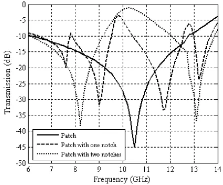
Fig. 4 illustrates the frequency responses of the transmission coefficient for the three structures
individuals. The frequency response of the FSS 1, which uses the geometry shown in Fig. 2(b),
exhibited four resonance bands with resonance frequencies. The FSS 2 uses a conventional
rectangular patch as unit cell element as shown in Fig. 2(a). In this case, a unique resonance band
occurs. The frequency response of the FSS 3, which uses the geometry shown in Fig. 2(c), exhibited
two resonance bands.
These resonance bands are listed in Table I. The idea is to cascade the three FSS, combining the
resonance bands of each structure, to obtain a UWB response.
TABLE I.RESONANCE FREQUENCIES AND BANDWIDTHS FOR INDIVIDUAL FSS
FSS1 FSS2 FSS3
fR (GHz) BW (GHz) fR (GHz) BW (GHz) fR (GHz) BW (GHz)
7.60 (band 1) 1.35 (band 1) 10.50 (band 1) 6.50 (band 1) 8.20 (band 1) 3.05 (band 1) 9.00 (band 2) 1.65 (band 2) - - 13.10 (band 2) 1.80 (band 2)
11.70 (band 3) 2.15 (band 3) - - - -
13.20 (band 4) 0,70 (band 4) - - - -
III. EXPERIMENTAL RESULTS AND DISCUSSIONS
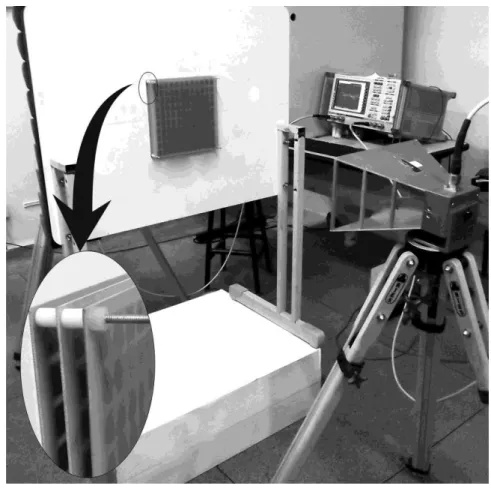
To validate our analysis, the three FSS prototypes were built and experimental characterizations
were performed. So, we can compare our simulated results with measurements. Measured results were
accomplished with the use of a Rohde & Schwarz vector network analyzer (ZVB-14), with range of
10 MHz – 14 GHz, and two horn antennas operating in the range of 700 MHz – 18 GHz with 16 dBi
of gain. The experimental results were not exhibit in [10]. A photograph of the front view setup
measurement is shown in Fig. 5. The support which the FSS are fixed is circulated by absorbers to
avoid diffraction at the edges.
Fig. 5. Front view of the measurement setup.
Fig. 6 shows a back view of the support with the FSS fixed and a detail of what the FSS are spaced.
We used spacers of Teflon with 5 mm of height. Two spacers were used between each FSS. Fig. 7
Fig. 6. Back view of the measurement setup and a detail of gaps between FSS.
Fig. 7. Photograph of the fabricated FSS and Teflon spacers.
Fig. 8 shows a comparison between numerical and measured results for FSS1 using a conventional
rectangular patch with one notch as cell element. Measured results present three resonant bands,
and second bands behave as a single band with bandwidth equal to 2.61 GHz. Also in this case, a
good agreement between results is observed.
Fig. 8. Comparison between numerical and measured results for FSS1.
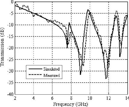
Fig. 9 shows a comparison between numerical and measured results for FSS2 using a conventional
rectangular patch as a cell element. Measured results present a resonance frequency equal to 10.58
GHz and our simulated results present a resonance frequency equal to 10.50 GHz. The measured
bandwidth was equal to 5.10 GHz while simulated results present a bandwidth of 6.50 GHz. A good
agreement between results is observed.
Fig. 10 shows a comparison between numerical and measured results for the FSS3. Measured and
simulated results exhibit two resonant bands and a good agreement between results is observed.
Fig. 10. Comparison between numerical and measured results for FSS3.
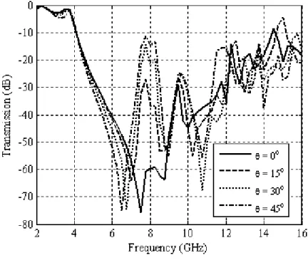
Based on the above analysis, a cascaded FSS structure is simulated using Ansoft Designer software
and the corresponding simulation results are shown in Fig. 11. The transmission coefficient curves of
FSS composite structure versus frequency for 0o ~ 45o angle of incidence and both polarization
(vertical and horizontal) wave are shown in Fig. 11(a) and 11(b). It was seen in Fig. 11 that the
stopband bandwidth of the FSS structure exhibits angular stability for vertical polarization
maintaining the stopband bandwidth equal to 10.30 GHz (4.05 GHz – 14.35 GHz). For horizontal
polarization the FSS structure exhibits angular stability until = 15o. Above this value the stopband
bandwidth decreases to 4.5 GHz, what still is a very wide bandwidth, but shows that for horizontal
polarization the cascaded FSS do not exhibit angular stability.
To demonstrate the accuracy of simulation results, experiment sample is fabricated. The measured
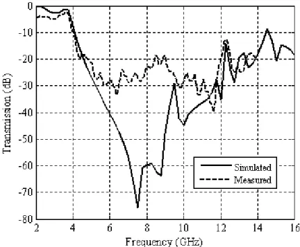
results about transmission curves for both polarizations are shown in Fig. 12 and Fig. 13. In Fig. 12
we have a comparison between numerical and measured results for a three layer FSS cascading FSS1,
FSS2 and FSS3. The simulated frequency response of the three overlapped FSS exhibit a bandwidth
of 10.12 GHz (4.00 GHz – 14.12 GHz). We can note that exist a difference of amplitude from 5 GHz
to 11 GHz. However, we are interested in the – 10 dB level and, bellow of this reference level, these
differences are not relevant. A vertical polarization was considered in these results.
In Fig. 13 we done the comparison made in Fig. 12, but in this case, we consider a horizontal
polarization. The simulated frequency response of the three overlapped FSS exhibit a bandwidth of
(a) Vertical polarization.
(b) Horizontal polarization.
Fig. 12. Comparison between numerical and measured results for a three layer FSS for vertical polarization.
Fig. 13. Comparison between numerical and measured results for a three layer FSS for horizontal polarization.
Those results show that the structure can be used in UWB applications once that this technology has
a bandwidth of 7.5 GHz (3.10 GHz – 10.60 GHz) [11]. Measured results show that the bandwidth
starts from 4.05 GHz, for vertical polarization, and for 5.05 GHz, for horizontal polarization, what is
bigger than the lower frequency of UWB applications (3.10 GHz). These differences may be adjusted
bandwidth of the UWB FSS for both polarizations. The stop frequency was not detected in measured
results due to limitations in the frequency range of the vector network analyzer used in measurements
(10 MHz – 14 GHz). A little difference regards with bandwidth was obtained for vertical and
horizontal polarization, what shows that the structure has polarization stability. This stability can be
improved if equal periodicities were used in x and y directions.
Fig. 14 illustrates the phase of the reflection coefficient of the FSS (S11). It is evident that the
remains almost constant oscillating in a mean value of 163o over a stopband bandwidth. This shows
that the FSS designed don’t can be used in pulsed systems where linearly deceasing phase can be a key requirement.
Fig. 14. The reflection phase coefficient.
IV. CONCLUSIONS
This paper presented a new proposal for the design of a FSS bandstop filter with ultrawideband
behavior. The structure was designed using three FSS layers with rectangular patch and rectangular
patch with notches printed on a fiberglass dielectric substrate. A numerical analysis of transmission
properties of the designed individuals FSS was performed through simulations using Ansoft
DesignerTM commercial software. A numerical analysis of transmission properties of the designed
UWB FSS was performed. The proposed FSS proves to be a potential candidate for UWB
applications.
REFERENCES
[1] L. M. Araújo, R. H. C. Maniçoba, A. L. P. S. Campos, and A. G. d’Assunção, “A Simple Dual-Band Frequency Selective Surface”, Microwave and Optical Technology Letters, Vol. 51, No. 4, pp. 942 – 944, 2009.
[2] A. Kazemzadeh and A. Karlsson, “Multilayered Wideband Absorbers for Oblique Angle of Incidence”, IEEE Transactions on Antennas and Propagation, Vol. 58, No. 11, pp. 3637 – 3646, 2010.
[4] Y. Ranga et al., “Multilayer Frequency-Selective-Surface Reflector for Constant Gain over Ultra Wideband”, Proceedings of the 5th European Conference on Antennas and Propagation (EUCAP), pp. 332 – 334, 2011.
[5] M. Pasian et al., “Frequency Selective Surfaces for Extended Bandwidth Backing Reflector Functions”, IEEE
Transactions on Antennas and Propagation, Vol. 58, No. 1, pp. 43 – 50, 2010.
[6] S. Baisakhiya et al., Novel Compact UWB Frequency Selective Surface For Angular And Polarization Independent Operation, Progress in Electromagnetics Research Letters, Vol. 40, pp. 71 – 79, 2013.
[7] W. Li et al., “Novel Frequency Selective Surfaces with compact structure and ultra-wideband response”, 2012 Asia -Pacific Symposium on Electromagnetic Compatibility (APEMC), pp. 557 – 560, 2012.
[8] R. M. S. Cruz, A. G. d’Assunção, and P. H. F. Silva, “A new FSS design proposal for UWB applications”, 2010 International Workshop on Antenna Technology (iWAT), pp. 1 – 4, 2010.
[9] I. Sohail, Y. Ranga; K. P. Esselle; and S. G. Hay, “A frequency selective surface with a very wide stop band”, 2013 7th European Conference on Antennas and Propagation (EuCAP), Gothenburg, Sweden, 2013.
[10]A. N. Silva, F. M. Pontes, L. S. de Oliveira, J. C. Silva, and A. Gomes Neto, “Frequency Selective Surfaces With non
Fractal Geometry”, Proceedings of the 2011 SBMO/IEEE MTT-S International Microwave and Optoelectronics Conference, 2011.

![Fig. 2. Proposed geometries in [10]: (a) original rectangular patch element, (b) patch with one notch and (c) patch with two notches](https://thumb-eu.123doks.com/thumbv2/123dok_br/18887740.424229/3.892.272.630.556.982/proposed-geometries-original-rectangular-patch-element-patch-notches.webp)