Microstructure Evolution and Properties of Friction Stir Welding Joint for 6082-T6
Aluminum Alloy
Liangliang Zhanga , Xijing Wanga,b,*
Received: April 17, 2018; Revised: July 10, 2018; Accepted: July 23, 2018
To investigate the evolution of grain morphologies, grain boundary features, and dislocation structure in upper part of nugget zone during friction stir welding of 6082-T6 aluminum alloys,
electron backscattered diffraction and transmission electron microscope techniques were employed. The
results showed that the metal on retreating side of the weld zone produced thermoplastic deformation
during the welding process. The substructure of the lamellar dislocation wall formed at retreating side. Motivated by the welding thermal cycle, geometric dynamic recrystallization occurred in the substructure of the lamellar grains, leading to the lamellar array of grains. Discontinuous dynamic recrystallization occurred in the lamellar grain, leading the grain to be arranged in a "necklace" form. Simultaneously, the coarse grain of base material was refined. Due to the inhomogenous distribution
of stress during the welding process, the alternating presence of large grain and small grain regions
on advancing side took place. During the process of welding joint tensile, the fracture results from dislocation piling-up at the Mg2Si interface in large grains with a (111)[110] orientation. Thus, the advancing side becomes the weakest part of the mechanical properties in the welding joint,the tensile strength of the joint was 275MPa with a break elongation of 6%.
Keywords: 6082-T6 aluminum alloy, friction stir welding, dynamic recrystallization, EBSD.
*e-mail:wangxj@lut.cn
1. Introduction
The central goal of welding is to establish a link between
the welding process parameters and joint performance, and the material microstructure determines its performance.
Therefore, it is particularly important to research the relationship between the microstructure evolution law of
welded joints and their properties. The 6082-T6 aluminum
alloy can be used as a new lightweight material instead of traditional steel material for application in the transportation and structural engineering industry, and can reduce weight and achieve energy-saving and emission-reduction1. However, when the traditional fusion welding process is used to weld aluminum alloy, it is easy to produce pores, hot cracks and
other defects. Friction stir welding (FSW), as a new solid-state
connection technology, has the advantages of small welding
deformation, small residual stress and no solidification and liquation cracking2. High quality welding joint of aluminum alloy can also be obtained by FSW3.
In the process of friction stir welding, the weld metal has undergoes plastic deformation at high temperature4. The plastic deformation of face-centered cubic (FCC) metals is
realized by the movement and interaction of dislocations in the slip process, during which the slip surface and the slip direction rotate along a certain direction until reaching a
stable orientation. Thus, the grain of the FSW joint appears
in its preferred orientation; at the same time, the precipitation
of the alloy phase also affects the movement of dislocations. Many scholars5-7 have applied the electron backscattered diffraction (EBSD) to study the law of grain orientation evolution during the welding process. Suhuddin et al.6 observed that the {1 1 2}<1 1 0> shear texture formed around the keyhole given the shear stress introduced by the stirred pin, while, due to the nugget area undergoing static heat treatment, the {1 0 0}<1 0 0> cubic texture dominates in the
far away keyhole area. Some scholars8 have used transmission electron microscope (TEM) techniques to study the change
trend of dislocations in the grain and the distribution of the
precipitates during the welding process.
Besides, some scholars have studied the temperature field distribution during the FSW wielding process of 6082 aluminum alloy. Vermaa et al.9 studied the temperature field distribution in the FSW process of 6082 aluminum
alloy and the results showed that the temperature on the advancing side of the welding nucleus was higher than the
retreating side.Tamadon et al.10 discussed the evolution law of microstructure for the A6082-T6 aluminum alloy during
FSW by the metallographic etchants method and the results showed that the coarse grain of the base material was refined
with its morphology evolving from columnar grain to the
equiaxed grain of the weld nucleus. Moreover, the etchants
aState Key Laboratory of Advanced Processing and Recycling of Non-ferrous Metals,Lanzhou University
of Technology, Lanzhou 730050, China
bSchool of Materials Science and Engineering, Lanzhou University of Technology, Lanzhou 730050,
also clearly showed the polycrystalline structure, microflow
patterns, and the incoherent interface around the inclusion
defects. The electrochemical corrosion behaviors of FSW and mixed inert gas welding (MIG) joints of 6082 aluminum alloy and base material were investigated in a solution of 0.2 mol/L NaHSO3 and 0.6 mol/L NaCl using the potentiodynamic polarization curve, electrochemical impedance spectroscopy
(EIS) and scanning electron microscopy (SEM) observation11. These results showed that the corrosion rate of the FSW joint was less than those of the MIG joint and the base material. EIS Nyquist loops indicated that an inductive arc existed inthe complex plane. SEM observations showed that a few shallow pits occurinthe surface of the FSW joint; however,
a large number of deeper pits appear on the surface of the
base materials and MIG joint.
Compared to other 6000 series aluminum alloys, 6082
has a higher strength and better corrosion resistance due
to the presence of a higher amount of manganese. FSW is the most effective connection of aluminum alloy, so it is very important to study the FSW process of the 6082-T6 aluminum alloy.
In this paper, the 6082-T6 aluminum alloy processed
by FSW was studied. The grain orientation, dislocation
structure, and the distribution of precipitated phases on
the upper surface of the nugget were analyzed by EBSD and TEM. This provided a theoretical basis for the wide application of 6082-T6 aluminum alloy.
2. Materials and Methods
The base material was a 6082-T6 aluminum alloy with
the size 100 mm × 50 mm × 2 mm, and its composition is shown in Table 1(The data were obtained by EDS (Oxford Instruments, Oxford, UK)).
During the welding process, a cylindrical shoulder and a profiled pin were used to join along the rolling direction.
The diameter of the shoulder was 10 mm; the diameter of
the pin was 2 mm and the length of pin was 1.8 mm, as shown in Figure 1.
The optimal welding parameters were obtained by the orthogonal test methodEBSD and TEM tests were performed
for the joints under the optimal parameters to discuss the evolution law of structure during the FSW process. The
optimum process parameters were as follows: the welding speed was 80 mm/min; the rotation speed was 1000 r/ min; the inclination angle of tool was 3° and the additional
compression of the shoulder was 0.1mm. As the tool
walked 80 mm, the welding stopped immediately and the
dynamic organization was frozen by the ice water mixture. According to the flow law of viscoplasticity metal during the FSW process, the viscoplasticity metal flow first enters the retreating side and finally reaches the advancing side. The flow state of the viscoplastic metal in the nugget zone is controlled by the shoulder. The material flow determines
the preferred orientation of the grain in the nugget zone with
little change to the texture along the thickness direction.
In this paper, the upper surface of the nugget zone was
selected as the research object to analyze grain orientation
and dislocation structure12.
Therefore, as shown in Figure 2, region 1 was located at
the retreating side of the nugget, and region 2 was located in
the advancing side of the nugget. EBSD and TEM samples
Table 1. Nominal compositions of the 6082 aluminum alloy
employed in this work. (wt,%)
Si Mg Cu Ti Fe Cr Zn Al
0.97 0.67 0.07 0.01 0.37 0.01 0.06 Bal
Figure 1. Photo of welding tool
Figure 2. Welding direction and rotation direction of shoulder and sample location diagram of electron backscattered diffraction (EBSD)
were cut and intercepted by wire-electrode cutting in the
base material and nugget zone.
The upper surface of the EBSD sample was coarsely
ground with sandpaper, and after mechanical polishing, the
surface of the sample was subjected to electrolytic polishing in a 10% perchloric acid anhydrous ethanol solution with a polishing voltage of 20 V, liquid temperature of -20 ° C and a polishing time of 40 s. A field emission scanning electron microscope (Quanta 450 FEG) with EBSD probe (AztecX-Max80) and Channel 5 orientation analysis system was used to conduct the EBSD test at a voltage of 20 kV. In the
analysis process, the reference coordinate system is shown in
Figure 2. In the welding direction (WD), transverse direction (TD) and normal direction (ND), the grain orientation were
expressed in the form of (h k l)[(u v w)] where (h k l) is
perpendicular to the crystal plane of ND, and [(u v w)] is parallel to the direction of the WD crystal orientation. The grain boundary with amisorientation of 2 °~15 ° was defined as a small-angle grain boundary, and when larger than 15 °, a large-angle grain boundary was defined. The average grain size was calculated by the equivalent diameter method.
The uppe and lower surface of the TEM samples were
coarsely ground to 40 µm with a series of sandpapers and thinned to perforation on a double spray electrolytic
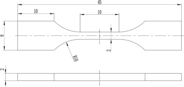
thinning apparatus. The surface of sample was subjected to electrolytic polishing in a 10% perchloric acid anhydrous ethanol solution with liquid temperature below -20 °C. TEM (JEM-2010) was used to observe the microstructure of the joints in different regions. The size of the tensile specimen is shown in Figure 3, where the weld was located at the center of the tensile specimen. At room temperature, tensile tests
on three parallel specimens of base metal and weld were
carried out on AG-10TA universal tensile machine with a rate of 0.2 mm/min, and the average value of the tensile tests was taken. Next, the fracture morphology was observed by
QUANTA FEG 450 heat field emission scanning electron microscope (SEM).
3. Results and Discussion
3.1 Microstructure of basematerial
The grain characteristics of the upper surface of the base
material were analyzed through the EBSD technique and
grain morphology was revealed by the orientation imaging
method. After the T6 heattreatment, the 6082 aluminum
alloy rolled plate experienced complete recrystallization with some grains growing more seriously13, as shown in Figure 4a. However, the flat grain structure after rolling treatment still retained an average grain size of 25 µm. As shown in Figure 4b, the grain misorientation is represented
by the histogram; misorientation is close to random
misorientation with no obvious preferred orientation. At
the same time, the precipitation phase distribution in the
base material was analyzed by TEM, and the results14,15 showed that there was needle-like precipitate β″ (Mg5Si6,
bottom center monoclinic structure) as shown in Figure 4c with the white arrow. The corresponding electoral electron diffraction pattern for β″ is shown in Figure 4d. The 6082 aluminum alloy after T6heat treatment still had a β phase (Mg2Si, Face centered cubic structure) as shown in Figure 4c with the black arrow, its corresponding electoral electron
diffraction pattern is shown in Figure 4e.
3.2 Macrostructure of nugget
Under the optimum welding parameters, a high quality welding joint was obtained, with good surface forming and no defects like flash, etc. As shown in Figure 5a, the grains on
the retreating side(RS) of the nugget elongated, as displayed
in Figure5b. Due to the good corrosion resistance of the 6082
aluminum alloy, it needs longer time for the metallographic specimen to be corroded, and therefore corrosion pit appears
in some localized sections. Note that equiaxed grains form in the advancing side(AS) of the nugget,as shown in Figure 5c.
3.3 Microstructure of Nugget
3.3.1 Retreating Side
The grain morphology of the retreating side of the
nugget zone (region 1) is shown in Figure 6a. Compared with the base material, the nugget grain was refined with
the average grain size of 5 µm. Owing to the shear stress introduced by the pin, the refined grain is elongated along the
tangential direction of the pin with a "necklace" form (The
white circles in Figure 6a and the red circles in Figure 6d represent the bead of the necklace, the black lines in Figure 6a and blue lines in Figure 6d represent the threading rope of the necklace). As shown in Figure 6c, the substructure of
the lamellar dislocation wall formed at the retreating side,
owing to the rotating extrusion effect of the pin. Aluminum
and its alloys undergo plastic deformation under elevated
temperatures with significant grain elongation and thinning
Figure 4. Microstructure of base material (a) grain morphology and grain boundary patterns; (b) distribution of grain misorientation;
Figure 5. Microstructure of welding joint (a) retreating side, (b) macroscopic morphology and (c) advancing side (The black arrows in
Figure5(a) and (b) indicate the corrosion pits)
Figure 6. Microstructure of the retreating side of the nugget (a) Grain morphology and grain boundary patterns; (b) distribution of grain misorientation; (c) structure and morphology of the lamellar subgrain; (d) grain morphology
taking place, which leads to a dramatic increase of the grain
boundary area. Motivated by the welding thermal cycle,
geometric dynamic recrystallization occurs in the substructure of the lamellar grains16,17, leading to the lamellar array of grains. At the same time, with the plug and recombination
of dislocations in the lamellar grains, subgrains consisting
of small-angle grain boundaries are formed.
Under the action of thermal activation energy, subgrains with similar orientation differences are combined into alarge subgrain by rotation. In the process of rotation, part of the
small-angle grain boundaries develop into large-angle grain boundaries, when the misorientation angles reach a critical value θc (θc ≈ 15°)18, a lot of new crystal grains appear in "necklace" form within the lamellar grain, as shown in Figure 6d. The necklace structure is one of the main characteristics of discontinuous dynamic recrystallization. However, the
necklace structure in the retreating side of nugget zone was
obviously different from that of discontinuous dynamic recrystallization. The structure in the retreating side of the
nugget zone was the accumulation of the necklace structure,
as shown in Figure 6a, whereas the necklace structure
appearing at the discontinuous dynamic recrystallization only occurred in the grain boundary19. Due to the dislocation accumulation and recombination, the increase of the grain boundary orientation angle and thus the formation of the large-angle grain boundary are often referred as continuous dynamic recrystallization20,21. As the continuous dynamic recrystallization occurs, part of the small angle grain boundaries are retained, resulting in the small angle grain
boundary components of the nugget area increasing to 42.5%, as shown in Figure 6b.
Under the effect of the welding thermal cycle, some
grains grew obviously, about 7 µm, as indicated by the
white arrow in Figure 6a. Smaller recrystallized (001)[100] cubic oriented grains between adjacent "necklace" grains were formed as indicated by the black arrow in Figure 6a. During the welding process, the hot deformation metal
stores the distortion energy in the grain boundary and
deformed substructure is first formed in the triangular grain
boundary, where the dislocation density of (001)[100] cubic
orientation, with simple dislocation configuration22 and low deformation energy storage23, was lower than that of the other substructure orientation. Second, based on the difference of the dislocation density and dislocation configuration of the
cubic orientated substructure, the (001)[100] cubic orientation
substructure achieves dynamic recovery due to the effect of
the welding thermal cycle and further becomes the core of
recrystallization. During the subsequent recrystallization
process, the crystal nucleus grows up normally by swallowing other substructure and (001)[100] cubic oriented grains in
the triangular grain boundaries finally appears. The above
process of nucleation and growth is known as discontinuous dynamic recrystallization20-21. The structure evolution of the retreating side is as follows: lamellar substructure, lamellar
structure, and "necklace" structure. As can be seen from Figures 6c-e, there are black-gray second-phase particles on
the retreating side of the nugget core with consisting of Al,
Mg, and Si elements at about 67.4%, 21.6% and 0.4% (mass fraction), respectively. It should be an Mg2Si phase
24. The EBSD results also show that region 1 contains Mg2Si with a fraction of 4.78% (volume fraction). The metal in the nugget
zone underwent large plastic deformation, resulting in the spheroidization of the second-phase particle morphology,
which reduced its surfaceand surface energy. Therefore, Mg2Si presented granular distribution in the retreating side of nugget the zone25.
3.3.2 Advancing Side
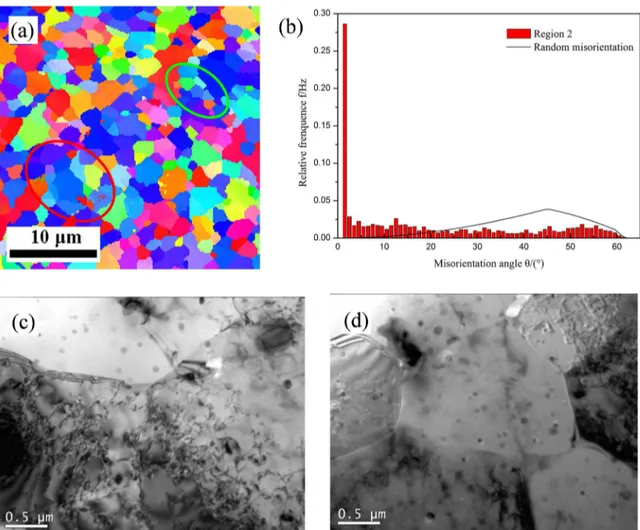
The grain morphology on the advancing side of the nugget
area, mainly consisting of equiaxed grains, was completely different from that on the retreating side and the distribution pattern of the “necklace” was not obvious. The proportion
of large grain increases and in some areas, there were all large grains with showing a (111)[110] shear orientation, as
indicated by the red circle in Figure 7a. However, in other regions there were fine equiaxed grains with a (001)[100] cubic orientation as indicated by the green circle in Figure 7a. Due to the inhomogenous distribution of stress in the welding
process, grains located in small stress areas underwent plastic deformation with a minimum orientation factorin the [100] direction of the (111) face26. Therefore, the (111)[110]shear orientation grains first appeared with the dislocation motion, resulting in a large number of dislocations inside the grain. However, as shown in Figure 7c, the dislocation wall did not form and there was no recrystallization phenomenon. Due to the high degree of plastic deformation in the large
stress area, the main deformation mechanism was the grain boundary slip and a lot of small(001)[100] cubic oriented grains were produced by recrystallization with a lower dislocation
density, as shown in Figure 7d. As seen from Figures 7c
and 7d, there were also black-gray second-phase particles
on the advancing side of the nugget zone. It should be the Mg2Si phase
24. The EBSD results also showed that zone 2 contained Mg2Si with a fraction of 6.45% (volume fraction)
According to the flow of viscoplastic metals in the FSW welding process, the viscoplastic metal flow first enters the retreating side, flows through the center of the nugget zone and finally reaches the advancing side27.Therefore, the plastic deformation of the advancing side of the nugget zone is less
than that of the retreatingside and nugget zone. However, the results of EBSD showed that the fraction of medium and
small angle grain boundaries on the advancing side was up
to 52.8%, as shown in Figure 7b.
The above phenomenon can be explained by the plasticity of the metal of the advancing side, so less distortion energy is stored in the grain boundary and intragranular grain, and only some of the grains achieved recrystallization while
of the weld that the tensile fracture mode of the joint was a typical ductile fracture.
Figure 9a indicates that the fracture center of the base material was mainly composed of small equiaxial dimples. Compared with the base material fracture the size of the dimples in the joint fracture is large and shallow with flat appearance as shown in Figures 9b-9f. This was due to the
uneven distribution of grain size in the advancing side of
Figure 7. Microstructure of advancing side of the nugget. (a)Grain morphology and grain boundary patterns; (b) distribution of the grain
misorientation;(c) structure and morphology of the coarse grain; and (d)structure and morphology of the fine grain.
Figure 8. Tensile properties of base material and welding joint.
side experienced large plastic deformation with high grain boundary storage energy and the temperature at the retreating side was higher than that of the advancing side during the welding process28, resulting in a high recrystallization degree of the retreating side and reduction of the small angle grain
boundary components.
3.4 Mechanical properties of base material and
joint
The mechanical properties test of the base material and
joint specimen are shown in Figure 8.The tensile strength of the base material was 330MPa with a break elongation of 20%. In addition, the tensile strength of the joint was 275MPa with a break elongation of 6% and the fracture position of the joint was at the advancing side of the nugget.
The tensile fracture morphology of the base material
and joint are shown in Figure 9. It can be seen that the
fractures were full of circular or ellipse dimples of varying
sizes with more and deeper dimples in the base material. It
Figure 9. Analysis of the scanning electron microscope fracture of the base material and joint. (a) base material;(b) joint; (c and e)local
the nugget and the large grain contained the second phase
particles of Mg2Si witha (111)[110] orientation.The face centered cubic metalorientationfactorin the [110] direction of (111) face was minimal26.
During the process of the tensile test, the plastic deformation of the large grain first occurred first and the
intragranular dislocations were plugged up in the second
phase. When the stress concentration reached the bonding strength between the Mg2Si phase and the aluminum body, the Mg2Si was separated from the interface of the body to form a microvoid, and the growth of the microvoid caused the
internal necking of the specimen. However, the connection of adjacent microvoids led to a partial rupture. The traces
left by the microvoid connections were the dimples on the fracture29. This showed that the plasticity and elongation of joint were less than the base material and the fracture position of the joint was the advancing side.
4. Conclusions
1. The substructure of the lamellar dislocation wall is formed at the retreating side due to the shear stress
introduced by the tool.
2. In the retreating side of the nugget zone, geometric
dynamic recrystallization first occurred, appearing as a lamellar structure. With the pile-up and
recombination of dislocations in the grains, subgrains were formed and the rotatation and merging of these subgrains due to the stress of the welding process resulted in the occurrence of continuous dynamic
recrystallization. Finally, new recrystallized grains
formed in the lamellar grains with presenting a
necklace arrangement. Simultaneously, the coarse grain of the base material was refined.
3. The metal in the nugget zone underwent large plastic deformation, which resulted in the spheroidization
of the second-phase particle morphology with Mg2Si presenting a granular distribution in the retreating
side of the nugget zone.
4. During the welding process, the stress distribution
was not uniform, leading to a large grain area and
a small grain area in the advancing side. The (111)
[110] orientation grain in the advancing side of the nugget had the smallest orientation factor and intragranular dislocations were piled up in the
second phase Mg2Si, resulting in fracture. Thus, the mechanical properties of the advancing side
became the weakest part of the joint.
5. Acknowledgments
This work was supported by major national science and technology projects under No.2012ZX04008011 and the
fundamental research funds of Gansu province for higher education institutions.
Conflicts of Interest: The authors declares that there is
no conflict of interest regarding the publication of this paper.
6. References
1. Liu W. Study on the Production Process of 6082 Aluminium Alloy Profiles for Ship. Aluminium Fabrication. 2001;24:19-22.
2. Su JQ, Nelson TW, Mishra R, Mahoney M. Microstructural investigation of friction stir welded 7050-T651 aluminium.
Acta Materialia. 2003;51(3):713-729.
3. Ericsson M, Sandström R. Influence of welding speed on the fatigue of friction stir welds and comparison with MIG and TIG. International Journal of Fatigue. 2003;25(12):1379-1387.
4. Xu WF, Liu JH, Chen DL. Material flow and
core/multi-shell structures in a friction stir welded aluminum alloy with
embedded copper markers. Journal of Alloys & Compounds.
2011;509(33):8449-8454.
5. Yuan GC, Liang CL, Liu H, Yuan Q. Crystal orientation in nugget zone of friction stir welded 5083 aluminum alloy plates.
Transactions of the China Welding Institution.
2014;35(8):80-84.
6. Suhuddin UFHR, Mironov S, Sato YS, Kokawa H. Grain structure
and texture evolution during friction stir welding of thin 6016
aluminum alloy sheets. Materials Science & Engineering: A.
2010;527(7-8):1962-1969.
7. Zhang CC, Chang BH, Tao J, Zhang T. Microstructure evolution during friction stir welding of 2024 aluminum alloy. Transactions
of the China Welding Institution. 2013;34(3):57-60.
8. Hou JC, Liu HJ, Zhao YQ. Influences of rotation speed on
microstructures and mechanical properties of 6061-T6 aluminum
alloy joints fabricated by self-reacting friction stir welding tool.
International Journal of Advanced Manufacturing Technology.
2014;73(5-8):1073-1079.
9. Verma S, Meenu, Misra JP. Study on temperature distribution during Friction Stir Welding of 6082 aluminum alloy. Materialstoday:
Proceedings. 2017;4(2 Pt A):1350-1356.
10. Tamadon A, Pons D, Sued K, Cuclas D. Development of Metallographic Etchants for the Microstructure Evolution of A6082-T6 BFSW Welds. Metals. 2017;7:423.
11. Peng Y, Shen C, Zhao Y, Chen Y. Comparison of Electrochemical Behaviors between FSW and MIG Joints for 6082 Aluminum Alloy. Rare Metal Materials and Engineering.
2017;46(2):344-348.
12. Mironov S, Sato YS, Kokawa H, Inoue H, Tsuge S. Structural response of superaustenitic stainless steel to friction stir welding.
Acta Materialia. 2011;59(14):5472-5481.
13. Zhang F, Liu YF, Li JL, Li YJ, Wang MJ. Effect of Solution Treatment Temperature on Microstructure and Properties of 6181A Aluminum Alloy. Foundry Technology.
2017;5:1042-1046.
14. Gong WB, Tian HJ, Liu W, Wang YJ, Wang SJ. Mechanical
aluminium alloy 6082-T6 plate. Rare Materials and Engineering.
2012;41:854-857.
15. Zandbergen HW, Andersen SJ, Jansen J. Structure Determination of Mg5Si6 Particles in Al by Dynamic Electron Diffraction Studies. Science. 1997;277(5330):1221-1225.
16. Huang K, Logé RE. A review of dynamic recrystallization phenomena in metallic materials. Materials & Design.
2016;111:548-574.
17. Song KH, Fujii H, Nakata K. Effect of welding speed on
microstructural and mechanical properties of friction stir welded
Inconel 600. Materials & Design. 2009;30(10):3972-3978.
18. Gourdet S, Montheillet F. An experimental study of the recrystallization mechanism during hot deformation of aluminium.
Materials Science & Engineering: A. 2000;283(1-2):274-288.
19. Ponge D, Gottstein G. Necklace formation during dynamic recrystallization: mechanisms and impact on flow behavior.
Acta Materialia. 1998;46(1):69-80.
20. Jata KV, Semiatin SL. Continuous dynamic recrystallization during friction stir welding of high strength aluminum alloys.
Scripta Materialia. 2000;43(8):743-749.
21. McNelley TR, Swaminathan S, Su JQ. Recrystallization
mechanisms during friction stir welding/processing of aluminum
alloys. Scripta Materialia. 2008;58(5):349-354.
22. Mao WM. Crystallographic Texture and Anisotropy of Metallic Materials. Beijing: Science Press; 2002. p. 116-117.
23. Etter AL, Mathon MH, Baudin T, Branger V, Penelle R. Influence of the cold rolled reduction on the stored energy and the recrystallization texture in a Fe-53%Ni alloy. Scripta
Materialia. 2002;46(4):311-317.
24. Tian RZ, Wang ZT. Aluminum Alloy and its Processing Handbook.
Changsha: Central South University Press; 2007. p. 250-253. 25. Frigaard Ø, Grong Ø, Midling OT. A process model for friction
stir welding of age hardening aluminum alloys. Metallurgical & Materials Transactions A. 2001;32(5):1189-1200.
26. Canova GR, Kocks UF, Jonas JJ. Theory of torsion texture development. Acta Metallurgica. 1984;32(2):211-226.
27. Gratecap F, Girard M, Marya S, Racineux G. Exploring material flow in friction stir welding: Tool eccentricity and formation of banded structures. International Journal of Material Forming.
2012;5(2):99-107.
28. Du YF, Bai JB, Tian ZJ, Zhang Y. Investigation on
three-dimensional real coupling numerical simulation of temperature
field of friction stir welding of 2219 aluminum alloy. Transactions
of the China Welding Institution. 2014;35(8):57-60, 70.
29. Wang XJ, Sun GP, Zhang J, Xu C, LI SW, Niu Y. Effects of heat treatment after welding on friction stir welding joints of high-strength aluminium alloy. The Chinese Journal of Nonferrous