¹Universidade Federal de Ouro Preto, Escola de Minas, Departamento de Geologia, Campus Morro do Cruzeiro, s/n, 35400-000 Ouro Preto, MG, Brazil
²Pattrol Investigações Geotécnicas, Rua Des. Continentino, 68, Caiçaras, 30770-180 Belo Horizonte, MG, Brazil
Manuscript received on June 6, 2016; accepted for publication on February 22, 2017
ABSTRACT
The aim of this study is to present analog models of flanking structures and to analyze the Fábrica Nova synform, Quadrilátero Ferrífero, Minas Gerais, from a geometric point of view. We set up seven models using a linear viscous silicone and produced flanking structures with a shear velocity of 2 cm h-1
. At different initial orientations with respect to the shear zone boundary, a rigid cross-cutting element with lubricated boundaries was deformed via sinistral bulk flow at a shear strain of γ = 1.28. The most interesting features of our experiments are the geometries of the different marker lines, which are heterogeneous and resulted from thickening and thinning of the silicone at the cross-cutting element terminations. To compare our analog models and the Fábrica Nova synform, we analyzed the outermost marker line of the analog models and the top surface of the Cauê Formation in the Paleoproterozoic metasediments. The best comparisons between the experiments and the natural example were obtained by our CIS90 model in terms of the flexure shape near the cross-cutting element and the cross-cutting element orientation. Thus, we suggest that the cross-cutting elements in both situations act as obstacles and consequently produce local perturbations in laminar flow.
Key words: physical modelling, flanking folds, silicone, Fábrica Nova synform.
Correspondence to: Caroline Janette Souza Gomes E-mail: caroline.janette@gmail.com
INTRODUCTION
In the present study, we present and discuss analog
models of flanking folds. We used a simple shear
rectangular box and a rigid cross-cutting element
with lubricated boundaries to analyze the Fábrica Nova flanking fold thesis presented by Rossi and
Endo (2015) from a geometric point of view.
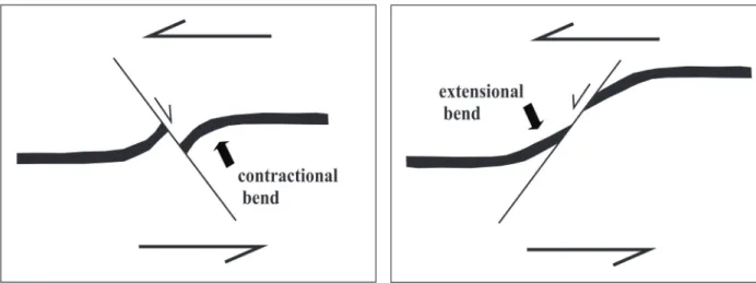
The term flanking structures was first used
by Passchier (2001) to describe deflections on the centimeter scale (Fig. 1). Passchier (2001) showed that these structures are isolated folds
that were formed in a number of different ways
and commonly show shear sense opposite to the
fault drag effect. Currently, scientists agree that the flanking structures are a deflection of the passive
planar fabric elements (e.g., foliation or layering)
faults) and can occur in several tectonic contexts
with a wide range of different geometric features.
A review of these concepts (their formation and geometric features) and the classification of
flanking structures were presented by Mukherjee
(2014).
Flanking structures were analyzed by using
analytical and numerical methods proposed by various authors (Gayer et al. 1978, Druguet et al. 1997, Zubriggen et al. 1998, Grasemann and Stüwe
2001, Grasemann et al. 2003, 2005, Wiesmayr and Grasemann 2005, Kocher and Mancktelow 2006, Mulchrone 2007, Exner and Dabrowski 2010, Mukherjee 2014). Analog modelling is less common. By using finite element modelling,
Grasemann and Stüwe (2001), Grasemann et al.
(2003) and Wiesmayr and Grasemann (2005) suggested that flanking fold deflections result from perturbations of the host rock near a cross-cutting
element (CE).
Hudleston (1989) generated flanking structures for the first time in analog experiments (he named them ‘paired hook-shaped asymmetric folds’) by using rectangular blocks (8 cm x 2.5 cm x 1.5 cm)
of plasticine and simple shear. In this study, the progressive rotation of an extensional fracture (a thin cut in the plasticine) resulted in the formation of folds. These folds were formed passively by local contraction rather than by slip along the fracture margins.
Odonne (1990) used paraffin wax layers with a
precut plane in a rectangular box (70 cm x 60 cm) to study the intensity of deformation resulting from uniaxial contraction around a fault. In addition to other findings, Odonne (1990) showed that heterogeneous strain around the CE varied between strongly and slightly deformed symmetrically aligned domains.
Exner et al. (2004) used a lubricated cut as the CE in silicone and a linear viscous material in a ring shear rig (set up with two concentric cylinders, one with radius of 1.76 cm and the other with 3.0 cm)
to test and extend previous numerical models of
type-s flanking folds to higher shear strains. These authors showed that both the offset and deflection of type-s flanking folds along a CE document the
local contraction of the planar fabric elements
parallel to the shear zone boundary. In addition,
these authors suggested that all flanking structures could evolve into type-s flanking folds at high shear
strain as the CE co-rotates.
Exner et al. (2006) used analog experiments to
investigate the formation of a flanking fold system around parallel and conjugate weak discontinuities
within a homogenous ductile matrix and compared
them with naturally occurring flanking folds. Passchier et al. (2008) first employed a rigid
CE in their analog experiments using silicone in a
simple shear rectangular rig that was progressively
deformed to a parallelogram-shaped box. The
authors analyzed the deformation of a lubricated
rigid CE when it was at a right angle to the passive
planar element (marker horizon or host element
(HE)). This lubricated and rigid CE produced
anticlinal and synclinal folding of the marker
horizons at the upper and lower tips of the CE in
the hanging wall and footwall, respectively.
Our experiments differ from the experiments
performed by Passchier et al. (2008) (who used
a rigid CE), mainly because a different type of
experimental box was used. In addition, in our
experiment, the CE was considered in several
different positions to overcome the inherent
problem of flanking folds characterized by only one marker horizon, which was the case of the Fábrica Nova synform. The occurrence of only one marker horizon makes it difficult to compare natural or experimental flanking folds, but this problem is reduced by comparing the marker horizon
MATERIALS AND METHODS
Seven models were built and deformed in a 33-cm-long, 20-cm-wide and 1.5-cm-deep rectangular box. An electric motor moved one half of the box horizontally at a velocity of 2 cm h-1 to cause a linear dislocation of 8 cm, which corresponded to a total
shear strain of γ = 1.28. The silicone used as a ductile
matrix consisted of mastic silicone rebondissant 36 (from Ets E. H. Roberts et Cie, CRC Industries
France) and alcohol, with a resulting viscosity μ =
1.7 x 10⁴ Pa s at 21°C. No lubricant was used at the
bottom of the box to trigger increases in the flow
lines at the upper silicone surface during simple shear.
Based on Grasemann et al. (2003) and Exner et
al. (2004), we used seven different initial ϕ angles
between the CE and the shear zone boundary
(ϕ = 15°, 30°, 70°, 90°, 110°, 150° and 165°).
The experiments were named according to the
values of their ϕ angles (CIS15, CIS30, CIS70,
CIS90, CIS110, CIS150 and CIS165). To ensure reproducibility, we performed each experiment twice.
Equidistant lines representing the HE were drawn on the surface of the models parallel to
the shear direction to track the deformation. In
the center of each model, we placed a thin 10-,
15- or 20-cm-long and 2-cm-deep metal plate to represent the CE (Fig. 2). According to Passchier et
al. (2008), a dyke may be represented by a CE with a rheology that is different from that of the matrix.
To simulate the kinematics of the ultramafic dyke in nature documented by an S/C mylonitic
foliation in the contact zones, we coated the rigid
CE with a thin film of liquid soap to simulate the
slip of the CE during the experiment.
During progressive deformation, the models were photographed at intervals of 1 cm of linear
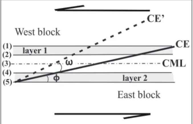
dislocation (γ = 0.16). We measured the CE rotation angle (ω) and the offset of the central marker line
(CML, in Fig. 3) on the photographs.
The use of silicone to reproduce the rheologic
conditions in the east Quadrilátero Ferrífero is
reasonable because the metamorphic grade reached the amphibolite facies during the Brasiliano tectonic event (Barbosa et al. 2012). Considering
the sparse knowledge of the flow parameters during
the formation of natural, mesoscopic ductile shear zones, we preferred not to present any scale factors in this study. Grasemann and Stüwe (2001) showed
that no significant difference in the geometry of flanking folds developed in linear or
power-law viscous materials. In addition, Kocher and
elements (foliation or metamorphic banding) do
not necessarily modify the flow field; therefore, we
are not concerned with the mechanical anisotropy of passive planar elements in this study.
RESULTS
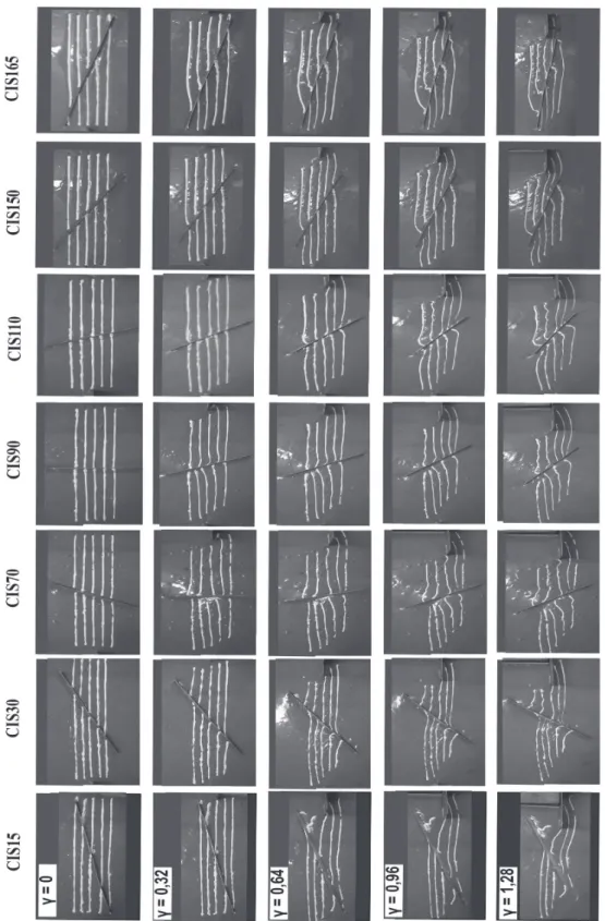
Photographs of the progressive deformation of analog experiments are presented in Fig. 4 with the
instantaneous flanking structures at intervals of γ
= 0.32.
Analysis of the photographs showed that
the sinistral shear produced different CE rotation
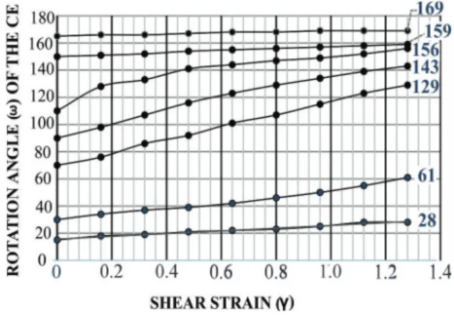
angles. Plots of the CE rotation (using the angle
ω) against the shear strain are presented in Fig. 5 and reveal that the final CE angle ɸ depends on its initial position. The total ω was small in the
experiments CIS165, CIS150 and CIS15 (4°, 9° and 13°, respectively), medium in the experiment CIS30 (31°) and high in the experiments CIS70, CIS90 and CIS110 (59°, 53° and 46°, respectively).
According to Kocher and Mancktelow (2005) and Mancktelow (2011), for a very elongate inclusion such as our CE the rotation should be effectively
identical to that of a passive line, irrespective of the viscosity contrast. Ghosh and Ramberg (1976) have shown that the maximum and minimum rate of rotation of an elongate inclusion in simple shear models occur when the inclusion is at a right angle and parallel to the direction of the simple shear, respectively. A high rotation rate produces a higher angle of rotation than a low rate, which explains
the different ω values observed in our experiments. The high total ω in models CIS70, CIS90 and CIS110 corresponds to the high offsets of the central marker lines (between 2.3 cm and 3.3 cm). Models
CIS15 and CIS165 reveal small offsets, while
CIS150 and CIS30 show zero offset. If we compare the first marker horizon (horizon (1), in Fig. 3) in adjacent blocks, we observe that the offset is large
in model CIS15, decreases progressively in models CIS30 and CIS70 and is absent in models CIS90, CIS110, CIS150 and CIS165. Overall, independent
of ω, slips are random and flexures of the marker
horizons near the CE are irregular. Exner et al. (2004) showed that the amount and even the sense of slip along the CE changes during the progressive deformation. Here, it is important to emphasize that
the quantitative kinematics were not analyzed in
detail in this study. Instead, the aim of this study was to describe the instantaneous effects of the rotation of the CE.
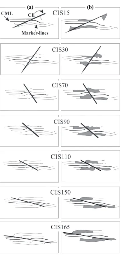
Figure 2 - A photograph of the initial experimental setup in plan view (model CIS90). The silicone is grey, and the front walls are black. The thick arrow indicates the direction of the movement of the upper half of the box, and the thin double arrows indicate the bulk simple shear.
Figure 3 - Schematic representation of the marker horizons.
In Fig. 6, we summarize our seven experiments at final deformation. The experimental results
show that the marker line deflections along the same block are heterogeneous. Marker lines 1 and 2 (which form layer 1 in Fig. 3) exhibit different deflection and offset geometries than marker lines
4 and 5 (which form layer 2 in Fig. 3). Independent
of their magnitude, marker lines 1 and 2 always show increasing offset or deflection in the upward direction along the CE, and marker lines 4 and
5 show decreasing offset or deflection in the downward direction (Fig. 6a). Thus, layer 1 reveals
thickening of the silicone at the upper tip of the CE (in the observation plane) in the east blocks in
all models (Fig. 6b) in addition to a concomitant
thinning at the opposite tip in the same block. In all of the experiments, thickening and thinning of the
hanging wall of the CE was always the opposite of
the thickening and thinning of the footwall.
DISCUSSION
Previous analog models mostly modelled the
CE as a weak inclusion (Odonne 1990, Exner et
al. 2004, 2006), with the exception of Passchier
et al. (2008), who simulated a rigid CE. While a weak CE, such as a lubricated cut in the silicone,
undergoes stretching during deformation, our rigid
CE acted as an obstacle and led to local thickening
and thinning at the opposite CE terminations of the
same block and to irregular marker line-deflections
even under low strain (Fig. 6).
Several authors have used similar deformation
rigs to simulate strike-slip structures and have
obtained homogenous deformation in purely brittle (e.g., Guerroué and Cobbold 2006) and ductile-brittle models (e.g., Richard et al. 1991, Casas et al. 2001). In our experiments, the movement of one half of the experimental box caused the silicone
flow and rotation of the CE. However, the rotation of the CE was slightly slower than the silicone flow. Thus, the silicone became thicker at the upper tip of
the CE in the east block and at the lower tip of the CE in the west block, producing irregular marker-line deflections.
In the present models, the unequal marker-line deflections and offsets along the same CE-block and along adjacent blocks deviate strongly from the regular flanking structure geometries obtained
by Passchier et al. (2008). In their experiments,
trains of hook-type flanking folds developed in
the hanging wall and footwall, with axial surfaces
parallel to the CE. These observed differences are
related to the distinct deformation set up, which
included a box with flexible plastic walls and a
lubricated bottom.
The deformation produced by rigid inclusions embedded in ductile matrixes during simple shear in analog models has been investigated by several authors (Ghosh 1975, Ghosh and Ramberg 1976, Marques and Cobbold 1995, Rosas et al. 2002). Previous studies have indicated that rigid inclusions act as an obstacle and consequently
produce perturbations in laminar flow, resulting
in complex strain patterns. Ghosh (1975) suggests that in simple shear, the distortion of a pre-existing foliation around a rigid spherical body, such as a porphyroblast, always produces a drag-pattern. The geometry (e.g., asymmetric, symmetric, with
Figure 5 - Plots of the CE rotation angle (ω) during progressive
Figure 6 - Summary of our final flanking structures. In (a), we present marker lines
only. In (b), we highlight the thickening and thinning (grey) domains. The heights
the same or different sense of drag) will depend on
the amount of deformation and on the initial angle
between the marker-lines and the direction of the
simple shear.
The preferential non-coaxial silicone bulk flow
has been tested in this study by using two previous experiments with and without the CE (Fig. 7). Fig. 7a shows the sigmoidal deformation of the vertical lines of an original quadratic grid drawn on the silicone. The continuous lines and the central segment of the dashed lines correspond to tiny
ripples that represent the flow lines of the silicone
that were perturbed by the introduction of the CE, as shown in Fig. 7b. The CE causes the deviation of the flow lines that consequently contour the
obstacle’s terminations. The east and west blocks
show similar flow line configurations. In our
seven experiments, the heterogeneous deflection geometries and offsets of the marker horizons near the CE suggest that the flow lines varied based on
the initial orientation of the CE.
Instantaneous perturbation flow fields were produced around the inclusions in the numerical models presented by Passchier et al. (2005). These authors present the instantaneous perturbation
fields around an elongated inclusion characterized by a weaker rheology than that of the matrix for
various orientations. In addition, these authors
compared their result to the flanking structures that
were studied by several other authors, including Grasemann and Stüwe (2001) and Grasemann et al. (2003). In the case of inclusions that are stronger than the matrix, the authors suggest perturbation flow patterns that have the same geometry and magnitude but opposite directions. This pattern was also the case for the CE in our models (see Passchier et al. 2005 for a detailed description).
THE EXPERIMENTAL FLANKING FOLDS AND THE FÁBRICA NOVA SYNFORM
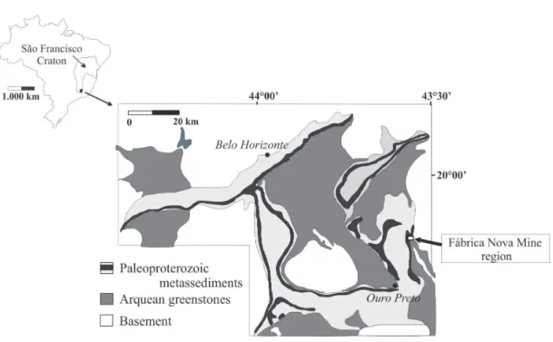
Rossi and Endo (2015) concluded that the
Fábrica Nova synform on the eastern flank of the
Santa Rita syncline in the east-central region of
the Quadrilátero Ferrífero (Fig. 8) is a flanking
fold based on detailed and regional scale
litho-structural mapping of the Fábrica Nova Mine
and its surrounding area. According to Dorr (1969), Maxwell (1972) and Rossi and Endo (2015), the Santa Rita syncline formed during the Transamazonian event (2.1 - 2.0 Ga) and consists of a sub-regional reclined synclinorial fold that is
cut by a complex system of thrust faults and mafic and ultramafic dykes. The Fábrica Nova synform is
an isolated, open fold (with a wavelength of a few
kilometers) with a Z-asymmetric fold geometry in
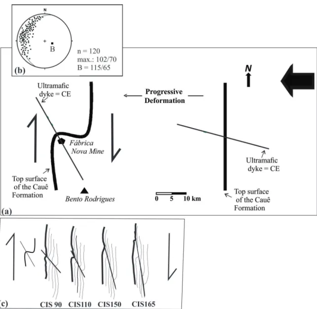
the horizontal view and a high E-SE plunge (Figs. 9a and b). Rossi and Endo (2015) concluded that
the clockwise vorticity of the folds resulted from
a local north-south simple shear. According to the authors, this local simple shear resulted from a
regional partitioning process around an ultramafic dyke during the E-W Brasiliano crustal shortening
tectonic event (0.6 – 0.8 Ga). The shortening
produced the clockwise rotation of the ultramafic dyke that acted as a rigid CE relative to the north-south marker horizon (the Cauê Formation) and consequently produced the flanking fold.
North-south trending shear zones are common features
in the Neoprotorozoic Araçuaí Orogen east of the Quadrilátero Ferrífero. According to
Teixeira-Silva et al. (2009), one of the main structures of
the crystalline core of the Araçuaí Orogen was
nucleated as a north-south, regional, west-verging contractional shear zone system that was partly
reactivated by a dextral strike-slip deformation
phase.
Fig. 9c shows line drawings of our experimental models CIS90, CIS110, CIS150 and CIS165
arranged in the same position as the Fábrica Nova
synform (presenting dextral simple shear). This arrangement reveals folding structures similar to
those in the natural Fábrica Nova synform. Among
those experiments, the model CIS90 was the most
Figure 7 - Photographs and line drawings of the silicone flow trajectory after a sinistral simple shear of γ = 0.8 (5 cm of linear dislocation) in previous models. (a) Without the CE and monitored by an initial square grid. (b) With
the CE in a model set up with four horizontal marker horizons. In the photographs, silicone is grey; the thin double arrows indicate the bulk simple shear and the thick arrow shows the movement of the upper half of the experimental box.
Figure 8 - Simplified geological map and the location of the Fábrica Nova Mine region in the Quadrilátero
final orientation of the CE. Conversely, due to their
initial CE-orientations, models CIS15, CIS30 and
CIS70 were not comparable to the Fábrica Nova
synform.
Because flanking structures are normally
described in the literature at the outcrop scale, the
dimensions of the Fábrica Nova flanking fold are
atypical. Nevertheless, the scale of flanking folds has already been discussed by Wiesmayer and
Grasemann (2005). These authors suggested that
flanking folds should constitute a new fault-related
fold model in addition to those usually described in fold and thrust belts (e.g., fault-bend folds, fault
propagation folds, detachment folds and break-Figure 9 - (a) Schematic map representing the top surface of the Cauê Formation (Quadrilátero Ferrífero) before and after the
formation of the flanking fold (modified from Rossi and Endo 2015). CE = cross-cutting element. The thick arrow indicates the sense and direction of the Brasiliano shortening event. (b) Structural data from the Fábrica Nova region: stereoplots refer to the
orientation of the poles of the bedding planes of the Cauê Formation (n = number of measurements, B = average orientation of flanking fold axis. (c) Comparison of the flanking fold of the Cauê Formation and the line drawings of the final flanking
deformation boxes by imposing strike-slip motion
of half of the box corroborates the results of earlier analog experiments and the proposal that the
Fábrica Nova synform represents a flanking fold.
Our analog experiments agree with previous numerical and analog models as follows:
- The final geometry of flanking structures is controlled by the initial angle ϕ of the CE, which influences the magnitude of the rotation angle, ω.
- The simple shear produces homogeneous
thickening and thinning at the CE terminations, which is an inherent feature of most flanking
structures, independent of the type of CE.
- The slip and the geometry of the marker lines near the CE suggest that flanking folds were formed by perturbations of the local flow field.
In contrast with previous flanking fold analog models, the strong thickening and thinning processes produced heterogeneous marker-horizon
deformation in this study. In four experiments (models CIS90, CIS110, CIS150 and CIS165), this
process generated flexures of the outermost marker horizon that matched those of the Fábrica Nova
synform.
We suggest that the north-south simple shear, which is recognized in the east Quadrilátero Ferrífero by Rossi and Endo (2015), produced local perturbations of the flow field around the mafic dyke that were similar to those described in the
analog experiments.
BARBOSA PF AND LAGOEIRO L. 2012. Sheared-bedding parallel quartz vein as an indicator of deformation processes. Tectonophys 564-565: 101-113.
CASAS AM, GAPAIS D, NALPAS T, BESNARD K AND ROMÁN-BERDIEL T. 2001. Analogue models of transpressive systems. J Struct Geol 23: 733-743.
DORR JVN. 1969. Physiographic, stratigraphic and structural development of the Quadrilátero Ferrífero, Minas Gerais, Brazil. US Geol Surv Prof Pap 641-A: 1-110.
DRUGUET E, PASSCHIER CW, CARRERAS J, VICTOR P AND DEN BROK S. 1997. Analysis of a complex high-strain zone at Cap de Creus, Spain. Tectonophys280: 31-45.
EXNER U AND DABROWSKI M. 2010. Monoclinic and triclinic 3D flanking structures around elliptical cracks. J Struct Geol32: 2009-2021.
EXNER U, GRASEMANN B AND MANCKTELOW N. 2006. Multiple faults in ductile shear zones: analogue models of flanking structure systems. In: Buiter SJH and Schreurs G (Eds), Analogue and Numerical Modelling of Crustal-scale Processes. Geol Soc Special Publ 253: 381-395.
EXNER U, MANCKTELOW N AND GRASEMANN B. 2004. Progressive development of s-type flanking folds in simple shear. J Struct Geol26: 2191-2201.
GAYER RA, POWELL DA AND RHODES R. 1978. Deformation against metadolerite dykes in the Caledonides of Finnmark, Norway. Tectonophys46: 99-11.
GHOSH SK. 1975. Distortion of planar structures around rigid spherical bodies. Tectonophys 28: 185-208.
GHOSH SK AND RAMBERG H. 1976. Reorientation of inclusions by combination of pure shear and simple shear. Tectonophys 34: 1-70.
GRASEMANN B AND STÜWE K. 2001. The development of flanking folds during simple shear and their use as kinematic indicators. J Struct Geol 23: 715-724.
GRASEMANN B, STÜWE K AND VANNAY JC. 2003. Sense and non-sense of shear in flanking structures. J Struct Geol25: 19-34.
GUERROUÉ E AND COBBOLD PR. 2006. Influence of erosion and sedimentation on strike-slip fault systems: insights from analogue models. J Struct Geol28: 421-430. HUDLESTON PJ. 1989. The association of folds and veins in
shear zones. J Struct Geol 11: 949-957.
KOCHER T AND MANCKTELOW NS. 2005. Dynamic reverse modelling of flanking structures: a source of quantitative kinematic information. J Struct Geol 27: 1346-1354.
KOCHER T AND MANCKTELOW NS. 2006. Flanking structure development in anisotropic viscous rock. J Struct Geol28: 1139-1145.
MANCKTELOW NS. 2011. Deformation of an elliptical inclusion in two-dimensional incompressible power-law viscous flow. J Struct Geol 33: 1378-1393.
MARQUES FG AND COBBOLD PR. 1995. Development of highly non-cylindrical folds around rigid ellipsoidal inclusions in bulk simple shear regimes: natural examples and experimental modelling. J Struct Geol17: 589-602. MAXWELL CH. 1972. Geology and ore deposits of the
Alegria district, Brazil. Washington. US Geol Surv Prof Pap 341J, 72 p.
MUKHERJEE S. 2014. Review of flanking structures in meso- and micro-scales. Geol Mag151: 957-974. MULCHRONE KF. 2007. Modelling flanking structures using
deformable high axial ratio ellipses: Insights into finite geometries. J Struct Geol 29: 1216-1228.
ODONNE F. 1990. The control of deformation intensity around a fault: natural and experimental examples. J Struct Geol12: 911-921.
PASSCHIER C. 2001. Flanking structures. J Struct Geol23: 951-962.
PASSCHIER C, HEESAKKERS V AND COELHO S. 2008. Two mechanisms for forming flanking folds In: De Paor DG (Ed), Making Sense of Shear (In honour of Carol Simpson). J Virtual Expl Electronic Edition.
PASSCHIER C, MANCKLETOW NS AND GRASEMANN B. 2005. Flow perturbations: a tool to study and characterize heterogeneous deformation. J Struct Geol 27: 1011-1026. RICHARD P, MOCQUET B AND COBBOLD PR. 1991.
Experiments on simultaneous faulting and folding above a basement wrench fault. Tectonophys 188: 133-141. ROSAS F, MARQUES FO, LUZ A AND COELHO S. 2002.
Sheath folds formed by drag induced by rotation of rigid inclusions in viscous simple shear flow: nature and experiment. J Struct Geol24: 45-55.
ROSSI DQ AND ENDO I. 2015. A structural model of the Fábrica Nova region, Santa Rita syncline, Quadrilátero Ferrífero: flanking folds as a folding mechanism. REM 68: 153-162.
TEIXEIRA-SILVA CM, ALKMIM FF AND PEDROSA-SOARES AC. 2009. Geometria e evolução do Feixe de Zonas de Cisalhamento Manhuaçu - Santa Margarida, Orógeno Araçuaí, MG. REM 62: 23-34.
WIESMAYR G AND GRASEMANN B. 2005. Sense and non-sense of shear in flanking structures with layer-parallel shortening: implications for fault-related folds. J Struct Geol27: 249-264.