NON-LINEAR ANALYSIS OF PIEZOLAMINATED
STRUCTURES
José Simões Moita*, Cristóvão Mota Soares**, and Carlos Mota Soares**
*Universidade do Algarve, Escola Superior de Tecnologia,Campus da Penha,8000 Faro, Portugal ** IDMEC-Instituto de Engenharia Mecânica-Instituto Superior Técnico, Av. Rovisco Pais,1096-
Lisboa Codex, Portugal.
Introduction
In the recent years the study of smart structures has attracted significant researchers, due to their potential benefits in a wide range of applications, such as shape control, vibration suppression, noise attenuation and damage detection. The applications in aerospace industry are of great relevance, such as in active control of airplane wings, helicopter blade rotor, space antenna. The use of smart materials, such as piezoelectric materials, in the form of layers or patches embedded and/or surface bonded on laminated composite structures, can provide structures that combine the superior mechanical properties of composite materials and the capability to sense and adapt their static and dynamic response, becoming adaptive structures. The piezoelectric materials have the property of generate electrical charge under mechanical load or deformation, and the reverse, applying an electrical field to the material results in mechanical strain or stresses.
Many researchers considering mainly linear analysis have carried out the modeling of composite structures containing piezolaminated sensors and actuators using the finite element formulation. A pioneering work is due to Allik and Hughes (1970) which analyzed the interactions between electricity and elasticity by developing a tetrahedral element. Recent surveys can be found in Benjeddou (2000), Senthil et al. (1999) and Franco Correia et al. (2000). Recently Yi et al. (2000) has developed a 3D finite element model to carry out the non-linear dynamic response of structures with piezoelectric laminae.
In this paper we present a finite element model, based on classical plate theory, for static non-linear analysis of plate/shell structures with piezoelectric sensors and actuators. A simple and efficient three-node triangular fat plate element is used. The formulation introduces one electric potential degree of freedom for each piezoelectric layer of the finite element. To show the applicability of the proposed model two illustrative numerical examples are presented and compared with alternative solutions.
Classical Plate Theory. Displacements and Strains.
The classical Kirchhoff plate theory is considered. The displacement field is given by:
x w z u t) z, y, u(x, 0 0 ∂ ∂ − = ; y w z v t) z, y, v(x, 0 0 ∂ ∂ − = ; w(x,y,z,t)=w0 (1)
y w x=−∂ ∂
θ and θy=∂w ∂x are the rotations about the Cartesian x and y axes respectively. The present theory considers large displacements with small strains. The Green’s strains components associated with displacement field of eq (1), are given (Reddy, 1999):
∂ ∂ ∂ ∂ ∂ ∂ ∂ ∂ − ∂ ∂ ε 2 2 2 0 x w + x v + x u 2 1 + x w z x u = 2 2 xx ∂ ∂ ∂ ∂ ∂ ∂ ∂ ∂ − ∂ ∂ ε 2 2 2 0 y w + y v + y u 2 1 + y w z y v = 2 2 yy (2) y w x w + y v x v + y u x u + x y w z x v y u0 0 2 2
+
xy γ ∂ ∂ ∂ ∂ ∂ ∂ ∂ ∂ ∂ ∂ ∂ ∂ ∂ ∂ ∂ − ∂ ∂ ∂ ∂ =Piezoelectric Laminates. Constitutive Equations
The piezoelectric constitutive equations, coupling mechanical and electrical fields, for a laminate, can be written as, Allik and Hughes (1970):
σ=Qε−eE
D=eTε +pE (3)
where σ=
[
σxxσyyσxy]
Tis the elastic stress vector and ε=[
εxxεyyγxy]
Tthe elastic strain vector, Q the elastic constitutive matrix, e the piezoelectric stress coefficient matrix, E theelectric field vector, D the electric displacement vector and p is the dielectric matrix. The
electric field vector is the negative gradient of the electric potential, which is assumed to be applied and varying linearly in the thickness direction, i.e.
E=−∇φ (4)
E=
{
0 0 Ez}
T (5)The finite element used here is a three-node triangular flat plate element with six mechanical degrees of freedom per node, three displacements and three rotations of the displacement field of Kirchhoff theory, and one additional degree of freedom for each piezoelectric layer. The element local displacements are expressed in terms of nodal displacements through shape functions given in terms of area co-ordinates, hence:
3 i e 1 1 i a d d= ∑N =N = ; e m m i 3 1 i m i m= ∑B d =B a = ε ; i b eb 3 1 i b i b = ∑B d =B a = ε ; E=−Bv φ (6)
For non-linear analysis, using an updated lagrangian formulation, Bathe (1982), we obtain:
(7) dA dz D 0 0 a dA dz 0 0 0 0 0 a + dA dz a 0 0 p e e Q 0 0 a N 1 = k A h h e t k t T mb T e t t t e t A h h k t T nl T N 1 = K A h h e t mb k T T mb T e t k 1 -k e t k 1 k e t k 1 -k ∑ ∫ ∫ σ φ δ ℜ = ∫ ∫ σ δ ∑ ∫ ∫ φ − φ ∆ + −
δ
v v v B B B B B B B The equilibrium equations in non-linear analysis of laminated structures with piezoelectricactuators, using an updated lagrangian formulation, can be written as:
{ }
{ }
t t{ }
int t t ) A ( L u t t mec ext t t ) k ( 1) -(k uu L uu t t t t F K F q K K ++∆∆ ∆ + ∆ + σ ∆ + ∆ + − ∆ − = ∆ + (A) v v (8) where{
A}
v ∆v = +∆ K F L(A) u t t actis an additional force vector due to the electrical potential applied
to the actuators.
In case of piezoelectric sensors the equilibrium equations are:
{ } { }
int t t t t ext t t ) k ( S 1) -(k uu L(S) ) ( L u ) S ( L u L uu t t t t F F q 0 0 0 K K K K K S ∆ + ∆ + ∆ + σ ∆ + ∆ + − = ∆ ∆ + ) ( vv v v v (9)Numerical Applications
1. Linear analysis of a piezoelectric bimorph beam.
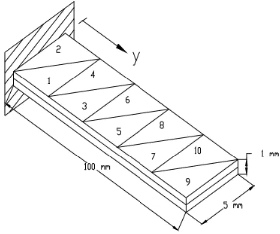
A linear analysis of a cantilivered piezoelectric bimorph beam, with two PVDF layers bonded together and polarized in opposite directions, with the dimensions indicated in Figure 2, is considered. The mechanical and piezoelectric properties of the PVDF are:
GPa, 2 E E1 = 2 = G12 =1GPA, 0, e e 0.046C/m ,p 1.062 x 10 F/m -10 33 2 32 31 12 = = = = ν
.The top and bottom surfaces of the beam are subjected to an electric potential of 1V. The deflections in diferrent locations of the beam, using a (5x2) element mesh, are presented in Table 1, which are compared with alternative solutions. The sensing voltage distribution of the bimorph beam for a prescribed tip deflection of 10 mm, is also analysed. The present predictions, and solutions obtained by other authors are shown in Table 2. The results are in good agreement with the alternative solutions.
Figure 2. Piezoelectric bimorph beam. Deflections x 10-7 m
Location y (mm) 20 40 60 80 100
Analytical solution
Suleman and Venkayya [12] 0.138 0.552 1.24 2.21 3.45 Q9-FSDT5P
Franco et al.[4] 0.138 0.552 1.24 2.11 3.45 FSDT4P
Suleman and Venkayya [12] 0.14 0.55 1.24 2.21 3.45
CPT Present Solution 0.137 0.550 1.240 2.210 3.45 Experimental
Suleman and Venkayya [12] - - - - 3.45
Sensed voltage (V)
Elements 1 and 2 3 and 4 5 and 6 7 and 8 9 and 10 Q9-FSDT5P Franco et al. [4] 290 226 161 97 32 FSDT4P Suleman e Venkayya [12] 290 - - - - Present Solution (CPT) 295 229 163 98 32
Table 2. Sensed voltage distribution for a tip deflection of 10 mm.
2.Adaptive composite plate with surface bonded actuators
A simply-supported square plate (axa), a=0.1 m, with two surface bonded piezoelectric layers PXE-52 is subjected to a uniform mechanical load of p0=10 kN/m
2
, and electrical potential of 151.35 V/-151.35 V. The lamination sequence of the plate is
[
p/45º/−45º/45º/p]
, where p represents the PXE-52 piezoelectric layers of thickness t=0.0002 m, and the three inside layers are made from S-glass/epoxy, with thickness t=0.0004 m. The properties of the PXE-52 areGPa, 5 . 62 E E1= 2= G12=24GPa,ν12=0.3, d31 =d32 =−280x10-12m/V,d33= 700x10- 12 m/V, p33=3.45x10⁻⁸ F/m, and for the S-glass/epoxy are E1=55GPa, E2=16 GPa, G12=7.6 GPa, ν12=0.28 . The results for different load cases, considering linear (L) and non-linear (NL) behavior of the plate, are presented in Figure 1.
0 0.5 1 1.5 2 2.5 3 -1 -0.9 -0.8 -0.7 -0.6 -0.5 -0.4 -0.3 -0.2 -0.1 0 0.1 0.2 0.3 0.4 0.5 0.6 0.7 0.8 0.9 1 w (mm) µ Carga mecânica (NL) Carga eléctrica (NL)
Carga mecânica + eléctrica (NL) Carga eléctrica (L)
Carga mecânica (L) Carga mecânica + eléctrica (L)
Conclusions
The result obtained for mechanical load only (µ=1., in Figure 1), in linear analysis, was compared with Franco et al., (1999), and an excellent agreement had been achieved. On other hand we observe that almost the same curves had been obtained for the cases of linear and non-linear analyses. The reason is because the range of mechanical and electrical loads is small.
References
Allik, H. e Hughes, T., (1970), “Finite Element Method for Piezoelectric Vibration”, Int. J. Num. Meth. Engng., 2, 151-157.
Bathe, K. J., (1982) , “Finite Element Procedures in Engineering Analysis”, Prentice-Hall Inc, Englewood Cliffs, New Jersey, USA.
Benjeddou, A., (2000), “Advances in Piezoelectric Finite Element Modelling of Adaptive Structural Elements: A Survey”, Computer and Structures, 76, 347-363.
Franco Correia, V.M., Mota Soares, and C.M., Mota Soares, C.A., (1999), “Optimal Design of Composite Structures with Integrated Piezoelectric Laminae”, C.A. Mota Soares et al. (eds), Mechanics of Composite Materials and Structures, 389-408.
Franco Correia, V.M., Aguiar Gomes, M.A., Suleman, A., Mota Soares, C.M., and Mota Soares, C.A., (2000), “Modelling and Design of Adaptive Composite Structures”, Comput. Methods Appl. Mech. Engrg., 185, 325-346.
Senthil, V.G., Varadan, V.V., and Varadan, V.K., (1999), “A Review and critique of Theories for Piezoelectric Laminates”, Smart Material Structures, 9, 24-28
Reddy, J. N., (1997), “Mechanics of Laminated Composite Plates”, CRC Press, Boca Raton, New York.
Yi S., Ling, S.F., and Ying, M., (2000), “ Large Deformations Finite Element Analyses of Composite Structures Integrated with Piezoelectric Sensors and Actuators”, Finite Elements in Analysis and Design, 35, 1-15.