Vol. 2, No. 1, May 2005, 5 - 20
A Practical Fast Acting Control Scheme for Fuzzy
Logic-Based Voltage Stabilisation Control
E. E. EL-Kholy, A. EL-Sabbe,
S. S. Shokralla, Nancy A. EL-Hefnawy
1Abstract: This paper presents a simplified control model for stabilising a load voltage using a switched reactor in parallel with a fixed capacitor of static VAR compensator. Two IGBT’s are used to control the reactance of the switched reactor. A uniform pulse width modulation is used for controlling the two switches. The compensator has a simple control circuit and structure. A complete modelling and numerical simulation for the proposed systems are presented. A high speed Digital Signal Processor is used for implementing proportional-integral (PI) and fuzzy load voltage controllers. Experimental results indicate the superiority of fuzzy logic control over the conventional proportional-integral control method. Simulation results are reported and proved to be in good agre-ement with the relevant experimental results.
Keywords: VAR compensator, Reactive power control, Load voltage stabilisa-tion, Fuzzy logic control.
1
Introduction
In recent years, the demand for controllable reactive power source has gone up mainly for efficient and reliable operation of ac electric power system [1]. VAR compensators should be controlled to provide rapid and continuous reactive power supports during static and dynamic power system operating conditions [2]. Advances in power electronics technology have allowed the development of various types of controlled electronics VAR compensator for power system applications [3-4].
There have been several papers published regarding the use of shunt compensating capacitors with series harmonic suppressor inductors in power factor correction and terminal voltage stabilisation of nonlinear loads. There are various static VAR compensator topologies based on forced commutated voltage source inverter [5-12]. In reference [6], scheme uses a filter reactor on the line side and self-controlled dc bus. The modulation index is controlled directly by the VAR calculator. The scheme allows the use of optimized PWM patterns for
6
harmonic rejection and is suitable for slow varying VAR demand applications. In reference [7], the modulation index is fixed and the capacitor voltage is controlled so that the inverter output voltage matches in magnitude the line voltage. The capacitor voltage control is achieved through phase shifting of the inverter voltage with respect to the line voltage. In spite of its simplicity, the load angle control scheme does not allow very fast response to be achieved particularly at high power ratings. Thyristors controlled reactors are a source of harmonics distortion in power systems [7].
In reference [8], two filter arms are considered; one is tuned for third harmonic frequency and other is for the fifth one. These filters are used to eliminate the third and fifth current harmonics as well as reducing the terminal voltage distortion. Synchronous compensators, mechanically switched capacitors and inductor and saturated reactors have been applied for many years to control the system voltage. Also, thyristor controlled reactor (TCR) devices together with fixed capacitors (FC) or thyristor – switched capacitors (TSC) have been used. The rating of inductors and capacitor used in the TCR/FC or TCR/TSC scheme, in most cases, exceed the reactive power supplied or absorbed by the scheme. This leads to considerable expenses and large requirement for land on which to locate the compensator [9]. Steady–state characteristics are reported for open loop systems for switch reactor based static VAR compensators [10]. In reference [11], a static reactive power compensator is designed to be capable of supply both balanced and unbalanced reactive power demands. In reference [12], error-driven, error-scaled, self-adjusting SVC-control strategy is driven by the presence of a nonlinear dynamic loads. This control ensures adequate compensation level and damping effectiveness at all times based on the magnitude of the excursion error deviation-vector in the error hyperplane.
In this paper, an efficient switched reactor in parallel with a capacitor for static VAR compensator is presented. To overcome the low–order harmonics and slow response associated with the conventional thyristor controlled reactor compensators, the uniform pulse width modulation is used for controlling the reactance of the switched reactor. The proposed system is implemented using a high speed digital signal processor (DSP) for PI and/or fuzzy logic load voltage controllers. The system behaviour under steady-state and transient condition is obtained and proved the superiority of the fuzzy logic controller over the conventional PI controller method. There are agreement between the simulation and experimental results.
2
Description of the System
7
control the reactance of the switched reactor. The simulation and experimental results are verified using an inductive load and /or dynamic load. The source reactance is taken 15 % to 20 % of the load impedance and the source resistance is taken 10 % of the source reactance [8]. The values of the controlled reactance and capacitance of the compensator are selected according to the following relationship [8]:
1 sin 1
1 = φ
ω = ω
θ zL
L
C . (1)
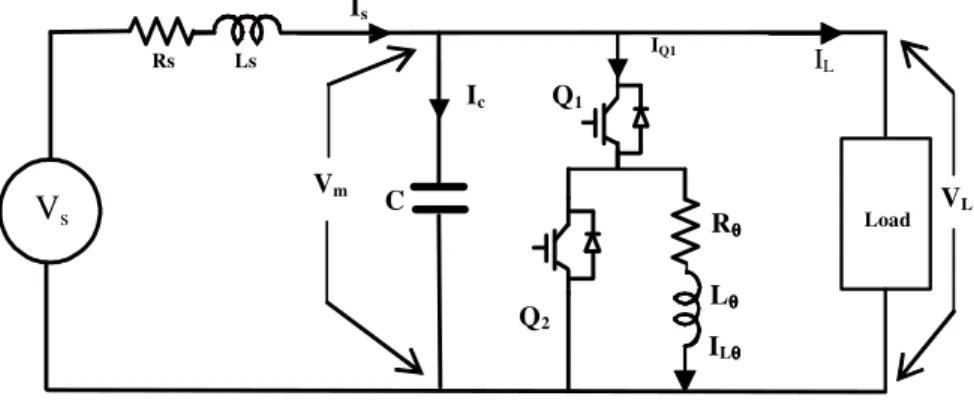
The parameter values of the designed system are given in the Appendix. The differential equations that describe the mode of operation for this system are given in reference [10]. The gate pulses are achieved by comparing the controller output with the triangular carrier signal using the DSP. The operation principle of the proposed system can be illustrated in Fig. 1. The two switches Q1 and Q2 represent two self–commutated bi-directional switches. Switch Q2 is
used to freewheel the controlled inductor current (iLθ) when Q1 is off. Through
high frequency switching, the fundamental component of the inductor current (iLθ) can be controlled by controlling the output, to stabilise the load voltage at
constant value. Rs Rθθθθ Ls Is Vm C Lθθθθ ILθθθθ
IQ1 Q2 Ic VL IL Vs Q1 Load
Fig. 1– Schematic diagram of proposed system.
3
Fuzzy Controller for Load Voltage Stabilisation
The inputs of the fuzzy controller are the error e(k) and the change of error ce(k), which are defined as:
e (k) = Vref – Vm (k), (2)
8
where Vm (k) is the present load voltage, Vref is the reference voltage, and the
subscript k denotes values taken at the beginning of the kth switching cycle. The output of the fuzzy controller is the control voltage and is defined as:
7Vc (k) = Vc (k-1) + ξ∆ Vc (k), (4)
where ∆Vc (k) is the inferred change of control voltage by the fuzzy controller at
the kth sampling time, and ξ is the gain factor of the fuzzy controller. Adjusting ξ can change the effective gain of the controller.
The values of e(k), ce(k) and ∆ Vc(k) are normalized. The triangular shape
of the membership functions of this arrangement presumes that for any particular input there is only one dominant fuzzy subset. Also, for any combination of e and ce, a maximum of four rules are adopted.
The derivation of the fuzzy control rules is heuristic in nature and based on the following criteria:
1.when the load voltage of the common coupling bus-bar is far from the set point, the change of control signal must be large so as to bring the output to the set point quickly;
2.when the load voltage of the common coupling bus-bar is approaching the set point, a small change of control signal is necessary.
3.when the load voltage of the common coupling bus-bar is near the set point and is approaching it rapidly, the control signal must be kept constant so as to reduce overshoot;
4.when the set point is reached and the output input still changing, the control voltage must be changed a little bit to prevent the load voltage from moving away;
5.when the set point is reached and the load voltage is steady, the control voltage remains unchanged;
6.when the load voltage is above the set-point, the sign of the change of control voltage must be negative; and
7.when the load voltage is below the set-point, the sign of the change of control voltage must be positive.
The inference result of each rule consists of two parts, the compatibility (weighting factor) wi of the individual rule, and the degree of change of control
signal Ci according to the rule. The weighting factor wi is obtained by applying
the minimum operation on µ(e0) and µ(ce0), where e0 and ce0 are the singleton
inputs of e and ce. Ci is obtained from the rules, which show the mapping from
the product space of e and ce to Ci. The inferred output of each rule can therefore
be written as:
9
where ∆VCi denotes the change of control signal inferred by the i th
rule. After collecting all the results, a crisp value of the change of control voltage can be obtained. Here the method of the center of gravity is preferred. The resultant change of control signal can be found as:
∆Vc (k) =
∑
∑
∑
∑
= = = =∆
=
N i i N i i i N i i N i ciw
C
w
w
V
1 1 1 1, (6)
where N is the maximum number of effective rules.
4
Simulation and Experimental Results
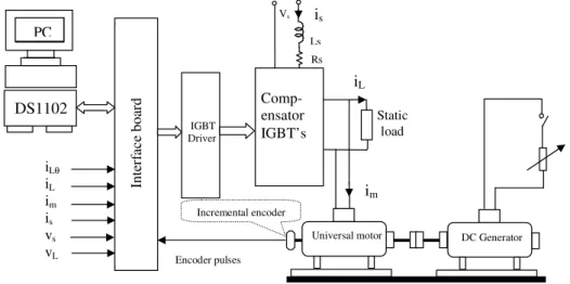
The proposed system is designed and implemented using DSP to verify the load voltage control requirements with PI controller and/or fuzzy logic controller. The experimental set-up is shown in Fig. 2, the load is static and/or dynamic. A universal motor under test is coupled to a self-excited dc generator, acting as a load. An incremental encoder is coupled to the motor shaft to measure the motor speed. The load, supply, and compensator current are sensed using hall-effect transducers, which have good linear response over wide range. Also, the load and supply voltages are sensed using voltage transducer, which has good linear response over wide range. This system is fully controlled by using dSPACE (DS1102) controller board, which is installed on a PC computer.
The behaviour of this system under steady state and transient conditions are obtained for static inductive load. The system has been tested using dynamic load, which is the universal motor. These results show the accuracy of the developed simulation when compared with the experimental results.
DS1102 Comp-ensator
IGBT’s Vs Static load IGBT Driver
iLθ
iL im is vs vL iL im is Ls Rs Encoder pulses PC In te rf ac e b o ar d DC Generator Universalmotor Incremental encoder
10
4.1 Open –loop PI controller for static load
Fig. 3 shows the experimental waveforms of the supply voltage (vs) and
current (is) with duty ratio equal to 0.7. It is observed that the power factor at
common coupling bus-bar near unity power factor. Also, it is clear that the supply voltage and current waveforms are sinusoidal.
Fig. 3– Experimental waveforms for supply voltage and current.
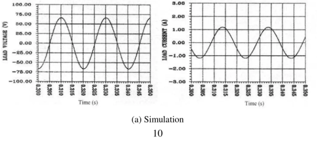
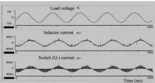
Fig. 4 shows the simulation and experimental waveforms of the load voltage (vL) and current (iL). It is noticed that the waveforms are sinusoidal. Fig. 5 shows
the experimental load voltage (vL), compensator inductor current (IL ) and
switch Q1 current (iQ1). It is observed that the inductor current lags the common
coupling load voltage by 90o.
11
(b) Experimental
Fig. 4 – Simulation and experimental results for load voltage and current.
Fig. 5– Experimental waveforms for load voltage, inductor and switch current.
4.2 Closed loop PI controller for static load
4.2.1 Reference voltage step change
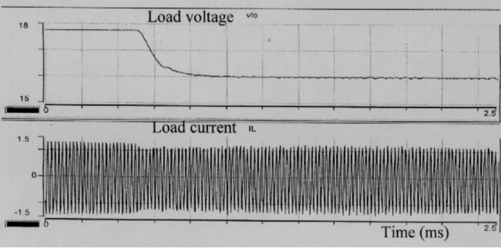
Figs. 6 and 7 show the variation of the load rectified output voltage sensor
12
Fig. 6– Variations of the load voltage and current due to a positive step change in reference voltage.
Fig. 7–Variations of the load voltage and current due to a negative step change in reference voltage
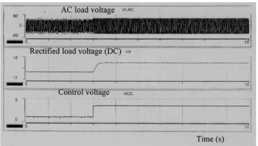
4.2.2 Load change
13
Fig. 8 –Variations of load voltage and control voltage due to positive and negative load change
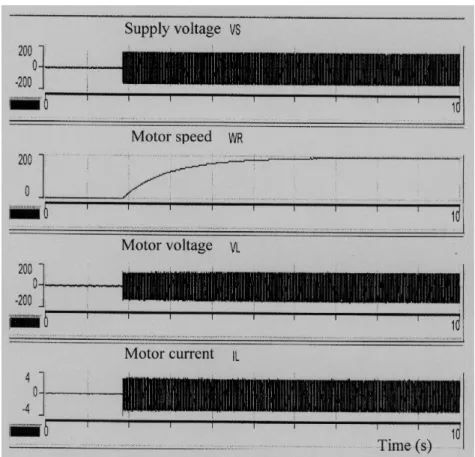
4.2.3 Open and closed loop run-up for the universal motor
Fig. 9–Open loop run-up behaviour for half load.
14
time for closed loop system is decreased and the common coupling bus bar voltage remains constant.
Fig. 10–Closed loop run-up behaviour for half load and Vref =140V.
4.3 Closed loop fuzzy logic controller
The effectiveness of the proposed fuzzy logic controller on the transient and dynamic characteristics of the load voltage stabilisation is investigated.
4.3.1 Reference voltage step change for static load
15
Fig. 11– Responses due to positive step change in reference voltage.
Fig. 12–Responses due to negative step change in reference voltage.
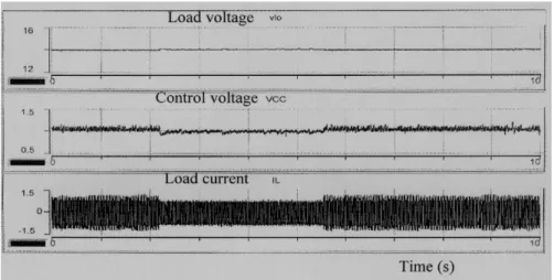
4.3.2 Static load change
16
load change for closed-loop voltage stabilisation using fuzzy control system. It is clear that the response with fuzzy control is faster than with the PI controller and the load voltage is constant.
Fig. 13–Variations of load current, load voltage and control voltage due to positive and negative load change for closed loop fuzzy control.
4.3.3 Motor run-up using fuzzy control
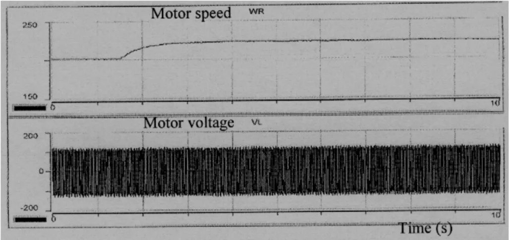
Fig. 14 shows the waveforms of the motor current, the motor voltage and motor speed during run-up at half-load and Vref = 120 V for closed loop voltage
stabilisation using fuzzy logic control. It is observed that the response time is faster than when using the PI controller.
17
4.3.4 Dynamic load change
Figs. 15 and 16 show the motor voltage and speed response due to positive and negative change in load torque with Vref = 120 V using fuzzy control. It is
clear that the load voltage is constant and the time response is faster than when using the PI controller.
Fig. 15– Response due to a negative change in load torque using fuzzy control.
Fig. 16– Response due to a positive change in load torque using fuzzy control.
5
Conclusion
18
improvement in the presence of feeder impedance. Appropriate parameters of the designed system are selected. The load terminal voltage, the load current and the supply current are shown to be close to the sinusoidal form.
The proposed system is fully controlled using the digital signal processor board. The proportional - integral voltage controller parameters are given to stabilise the common coupling bus-bar voltage. Moreover, the experimental study using DSP clearly indicates the superior performance of fuzzy logic control for static and or dynamic load. This is because it is inherently adaptive in nature. By good choice of control parameters, the fuzzy controller can give better results than the PI controller. Fuzzy control of the complete system gives good response in both the motor run-up and during disturbances.
6
Nomenclature
C: Compensator capacitor, µF
F: Motor viscous friction coefficient, Nm/r/s. Is,is: R.M.S. and instantaneous supply current, A
Ls: Supply inductance, H
Lθ,Ll: Controlled coil and load inductances, H
Rθ, Rl: Controlled coil and load resistances, Ω
Rs: Supply resistance, Ω
Vs,vs: R.M.S. and instantaneous supply voltage, V
Vm, vm: R.M.S. and instantaneous load terminal voltage, V
ZL: Load impedance, Ω φl: Load phase- angle
ω: Angular frequency
La, Lf: The armature and field of the motor inductances, H
Ra, Rf: The armature and field of the motor resistances, Ω
J: The moment of inertia, kgm2
Te,Tl: The electromagnetic and the load torque, Nm
KP: Proportional gain
19
7
Appendix
The parameter values of the designed system at 50 Hz are as follows:
Rl = 25 Ω Ll = 0.159 H
Rθ = 2.5 Ω Lθ = 0.199 H
Rs = 2.5 Ω Ls = 0.027 H
C = 55 µF The test motor data and parameters: 1/3 HP, 220 V, 1.9 A, 6000 r/min
Universal motor has the following measured parameters: Ra + Rf = 13.7 Ω, La + Lf = 0.169 H,
F = 0.00012 Nm/r/s, J = 0.003 kgm2
8
References
[1] S.Y. Lee, C.J. Wu, W.N. Chang: A Compact Control Algorithm for Reactive Power
Compensation and Load Balancing With Static VAR Compensator, Electric Power Systems Research, Vol. 58, No. 2, pp. 63-70, 2001.
[2] P.K. Shadhu Khan, J.K. Chatterjee: Operational Capability of Inductively Loaded Current
Controlled Solid-State Lead–Lag VAR Compensator, International Journal of Electrical Power & Energy Systems, Vol. 25, No. 4,pp. 275-292, 2003.
[3] C.S. Chang, Y. Qizhi: Fuzzy Bang-Bang Control of Static VAR Compensators for Damping
System-Wide Low-Frequency Oscillations, Electric Power Systems Research, Vol. 49, No. 1, pp. 45-54, 1999.
[4] H. Rastegar, M. Abedi, M.B. Menhaj, S.H. Fathi: Fuzzy Logic Based Static VAR
Compensators for Enhancing the Performance of Synchronous and Asynchronous Motor Loads, Electric Power Systems Research, Vol. 50, No. 3, pp.191-204, 1999.
[5] L. Moran, P.D. Ziogas, G.A. Joos: A Solid-State High-Performance Reactive-Power
Compensator, IEEE Transaction on Industry Application, Vol. 29, No. 5, pp. 969-978, 1993.
[6] C.R. Vidyashankar, A.K. Khargekar: A Practical Fast Acting Control Scheme for Static VAR
Compensator, Electric Machines and Power Systems, No. 1, pp. 357-366, 1986.
[7] G. Joos, L. Moran, P.D. Ziogas: Performance Analysis of a PWM Inverter VAR
Compen-sator, IEEE Transaction on Power Electronic, Vol. 6, No. 8, pp. 380-391, 1991.
[8] S.E. Haque, N.H. Malik, W. Shepherd: Operation of a Fixed Capacitor-Thyristor Controlled
Reactor (FC-TCR) Power Factor Compensator, IEEE Transaction on Power Apparatus and Systems, PAS-104, No. 6, pp. 1385-1390, 1985.
[9] J.B. Ekanayake, N. Jenkins, C.B. Cooper: Experimental Investigation of an Advanced Static
20
[10] H. Jin, G. Goos, G. Lopes: An Efficient Switched-Reactor Based Static VAR Compensation,
IEEE Transaction on Industry Application, Vol. 30, No. 4, pp. 998-1005, July/Aug. 1994.
[11] A.A. Amin: A Three-phase Foure-Wire Advanced Static VAR Compensator, International
Middle-East Power Systems Conference (MEPCON’2000), Cairo, Egypt, pp. 44-48, March 28-30, 2000.
[12] A.M. Sharaf, M.Z. El-Sadek, F.N. Abd-Elbar, A.M. Hemeida: A Novel Error Driven