A COMPARATIVE ANALYSIS OF CASCADED-MULTILEVEL HYBRID
FILTERS APPLIED IN POWER TRANSMISSION SYSTEMS
Alexandre G. Merçon
∗Lucas F. Encarnação
∗Luís F. C. Monteiro
∗Emanuel L. van Emmerik
†Maurício Aredes
∗∗Laboratório de Eletrônica de Potência e Média Tensão, Programa de Engenharia Elétrica
COPPE/Universidade Federal do Rio de Janeiro
Centro de Tecnologia, Bloco I, Sala 156, Cidade Universitária, Caixa Postal 68504, CEP: 21945-970, Rio de Janeiro, R.J., Brasil
†Laboratory of Electrical Power Processing, Faculty of Electrical Engeneering
Delft University of Technology Mekelweg 4, 2628 CD Delft, The Netherlands
ABSTRACT
Passive filters, commonly used to attenuate
non-characteristic harmonics in High Voltage Direct Current (HVDC) systems, stay at risk of disconnection from the system due to overcurrent problems. A possible solution to solve the problems involving high harmonic levels would be the use of pure active filters. However, this alternative is unpractical due to the high power of the transmission
systems. This paper proposes two different topologies
of hybrid filters to damp harmonic resonance in power transmission systems. The first one combines a small-rated active filter in series with passive filters, limiting overcur-rents, when existent, or improving its own quality factor. The second one consists of an active filter in parallel with passive filters, which compensates all eventual overcurrent
in the system bus. Both topologies utilizes the state of
the art in very high power semiconductors and multilevel power converters. Simulation results present a comparative
Artigo submetido em 10/06/2006 1a. Revisão em 16/01/07
Aceito sob recomendação do Editor Associado Prof. Enes Gonçalves Marra
analysis, highlighting the efficiency of, and the differences between, the two proposed hybrid filters.
KEYWORDS: Transmission systems, hybrid filters, cascaded multilevel power converters, power quality.
RESUMO
filtro ativo em paralelo com filtros passivos, compensando as eventuais sobrecorrentes no sistema onde está conectado. As duas topologias utilizam as mais novas tecnologias em dispositivos semicondutores para alta potência e converso-res multiníveis. Resultados de simulações apconverso-resentam uma análise comparativa, destacando a eficiência e as diferenças entre os dois filtros híbridos propostos.
PALAVRAS-CHAVE: Sistemas de transmissão, filtros híbri-dos, conversores multiníveis, qualidade de energia.
1 INTRODUCTION
The harmonic propagation in industrial power systems has become a problem that affects seriously the power quality in distribution feeders due to the wide use of non-linear loads such as rectifiers, inverters and cycloconverters (Watanabe and Aredes, 2002). This problem is even more amplified be-cause of the use of shunt capacitors installed on distribution systems for power factor correction. Normally, these capac-itive filters are designed considering only the fundamental frequency of the system, 50 or 60 Hz. The harmonic propa-gation generated by power electronic equipments may cause harmonic resonance between the line inductances and those shunt capacitors. Researches on harmonic damping in dis-tribution systems are in advanced stage and the use of active filters have presented good results (P. Jintakosonwit, 2003).
Recently, problems related to harmonic propagation have also been noticed in transmission systems, affecting the elec-tric system in a severe way. Important parts of the Brazil-ian transmission system, like the area connected to the High Voltage Direct Current (HVDC) system, have been present-ing this kind of problems (Plaisant and Reeve, 1999).
Passive filters at the Ibiúna substation, one of the converter stations of the Brazilian HVDC system, were designed to at-tenuate the harmonics generated by the converters as well as the non-characteristic harmonics generated by asymmetries in the converter transformers and the firing control. Since 1988, situations with high indices of harmonic distortion,
mainly the 5th order harmonic, have been detected. Due
to these high indices it was necessary to operate with two double-tuned passive filters for the 3rd and 5th harmonics. This is in disagreement with the original project, which was designed to operate with only one filter at this tuning, letting the other one as a backup filter.
At the Ibiúna substation, a pure active filter to solve the
prob-lem of the high5th order harmonic voltage in the passive
filters would not be economically and technically viable be-cause of the high power involved. A hybrid filter, consisting of an active filter combined with the existent passive filters, would be a less expensive solution, uniting the advantages of
both filters.
This paper proposes two hybrid filter topologies to work in high power systems such as HVDC systems. The first topol-ogy consists of an active filter in series with passive filters and the second one consists of an active filter in parallel with the passive filters. In both topologies the hybrid filter is in shunt with the system and multilevel converters are used to improve the filters capacity (J. Rodrígues, 2002).
2 THE IBIÚNA SUBSTATION
The Ibiúna substation is a part of the South - Southeast - Cen-tral West Brazilian transmission system and can be consid-ered a complex system with a wide variety of power-system equipments, such as HVDC converters, passive filter banks, synchronous compensators and transmission lines with dif-ferent AC levels coming from various parts of the power sys-tem.
With the purpose of testing the proposed hybrid filters, a sim-plified transmission system was modeled and simulated at
P SCAD/EM T DCT M version 3.0.8. The digital module consists on a three-phase bus bar where a bank of passive fil-ters and the active filfil-ters are connected. The bus bar is fed by a three-phase 345 kV voltage source and also connected in a three-phase unbalanced current source, which is used to
represent the5thharmonic pollution in the system. In the
fu-ture a complex system model with more than 2200 electrical nodes is going to be used, allowing simulation results closer to real situations.
3 SERIES HYBRID FILTER
3.1 Power Circuit
In the first topology (Figure 1), the hybrid filter is composed of a multilevel cascaded active filter in series with the ex-istent passive filters (F. Z. Peng, 1997). The active filter consists on two cascaded modules per phase, where each module is a single-phase voltage-source full-bridge inverter using four Integrated Gate-Commutated Thyristor (IGCT’s) and one capacitor (K. Satoh, 2001).
Phase Shift Carriers Pulse Width Modulation (PWM) tech-niques are used, resulting in a switching frequency of 3 kHz
in each phase (Y. Liang, 2000). The inverter uses the5th
har-monic tuned passive filters as output filters to reduce the high frequency harmonic components.
ade-345 kV
3rd/5thTuned
Passive Filter
C1
L1
C2
L2 R
C1
L1
C2
L2 R
C1
L1
C2
L2 R
Ca1 Ca2 Cb1 Cb2 Cc1 Cc2 345 kV
3rd/5thTuned
Passive Filter
C1
L1
C2
L2 R
C1
L1
C2
L2 R
C1
L1
C2
L2 R
Ca1 Ca2 Cb1 Cb2 Cc1 Cc2
Figure 1: Series hybrid filter at the 345 kV bus.
345 kV
vF
RF
IF5
5th Harmonic
Tuned Passive Filter Active Filter 345 kV vF RF IF5
5th Harmonic
Tuned Passive Filter
Active Filter
Figure 2: Series hybrid filter operation principle.
quate voltage and current levels, this configuration allows the use of small rated devices in the active filter, and it was not necessary to connect a matching transformer between the ac-tive and the passive filters. The instantaneous voltage drops over the IGCT’s are defined by the voltages at the DC-link capacitors, which are maintained below 1.5 kV in each mod-ule.
3.2 Operation Principle
Even for the tuned frequencies,5thharmonic for example,
the passive filters present non-zero impedance (Rf). Based
on this principle the active filter works in two distinct situ-ations, when the nominal current in the passive filters is not achieved, the active filter behaves like a negative resistance, generating a proportional voltage in counter-phase with the
detected5thharmonic current. This cancels the resistance of
the passive filters and improves its quality factor. When an overcurrent occurs, the active filter increases the resistance of the passive filters, generating a proportional voltage in phase
with the detected5thharmonic current, protecting it from an
excessive current value. This control is shown in Figure 2.
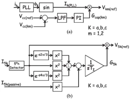
3.3 Control Circuit
The control-circuit consists of two distinct parts. The first one controls the DC-link voltage in each module (Figure 3.a),
and the second one regulates the5thharmonic current in each
V5k(ref)
(b)
I5k
e-s4π/3
e-s2π/3 x2
x2 x2 ∑ -+ I5k(passive) 1 sTI
__ G5k
x2
(a)
PI sin
ik Ik(PLL) x
LPF + -Vcc(ref) Vcc(km) Vkm(ref) Gcap(km) x
PLL φk
5ºh Detector
K = a,b,c K = a,b,c m = 1,2
V5k(ref)
(b)
I5k
e-s4π/3
e-s2π/3 x2
x2 x2 ∑ -+ I5k(passive) 1 sTI __1 sTI
__ G5k
x2
(a)
PI sin
ik Ik(PLL) x
LPF + -Vcc(ref) Vcc(km) Vkm(ref) Gcap(km) x
PLL φk
5ºh Detector
K = a,b,c K = a,b,c m = 1,2
Figure 3: DC-link voltage (a) and5thharmonic current (b)
control circuits .
phase of the passive filters (Figure 3.b).
As presented in Figure 3.a, the control circuit compares a
reference signal,Vcc(ref), with the capacitor voltage in each
module,Vcc(a1), for phase A (k = a) of the module 1 (m = 1).
The error passes through a low pass filter in order to reduce
the signal noise. A Gain,Gcap(a), is adjusted over the
fil-tered error signal by a Proportional Integrator (PI) controller. The output of the PI controller is multiplied by an unitary
si-nusoidal signal,Ia(P LL), which is synchronized by a
Phase-Locked-Loop (PLL) circuit (H. Fujita, 2002). Therefore, the
output generates a fundamental voltage reference,Va1(ref),
responsible to control the DC-voltage for its respective mod-ule.
Figure 3.b shows the control circuit for each phase of the
5th harmonic current in the passive filters. Instantaneous
aggregate-value concepts are applied to the5thharmonic
de-tected current,I5a, for phase A (k = a), which is extracted
from the detection circuit. This signal is compared with a5th
harmonic reference current,I5a(passive), and then integrated
to generate the5thharmonic current control gain,G5a. This
gain is multiplied by the5th harmonic current, generating
the 5th harmonic reference voltage, V5a(ref), which is
re-sponsible to control the5thharmonic current in phase A of
the passive filters.
The sum of the reference voltages,Va1(ref)andV5a(ref),
re-sults in a reference voltage that is used in an phase shift PWM inverter to generate the compensation voltage for phase A of the module 1. The other references are generated by a similar process. The differences between them are only the currents and capacitor voltages measurements. The reference signal,
I5a(ref), is a calculated value based on the maximum
345 kV
3rd/5thTuned Passive Filter
C1
L1
C2
L2 R C1
L1
C2
L2 R C1
L1
C2
L2 R 1
2
10 1
2
10 1
2
10
345 kV
3rd/5thTuned Passive Filter
C1
L1
C2
L2 R C1
L1
C2
L2 R C1
L1
C2
L2 R 1
2
10 11
2 2 2
10 10
1
2
10 11
2 2 2
10 10
1
2
10 11
2 2 2
10 10
Figure 4: Shunt hybrid filter at the 345 kV bus.
4 SHUNT HYBRID FILTER
4.1 Power Circuit
In the second proposed topology the hybrid filter is consti-tuted by a shunt connection involving an active filter and the existent passive filters. The active filter consists of a three-phase cascaded multilevel voltage-source converter, where each phase-leg circuit is composed by 10 power modules connected in series. This structure allows 21 voltage levels on its AC side. Each power module is a single-phase full-bridge inverter with one capacitor at its DC-link and four IGCT’s, switched through a phase-shift carries PWM. The IGCT’s are switched at 800 Hz, which results in an equiva-lent switching frequency of 8 kHz due to the multilevel struc-ture. The bank of high-pass passive filters at the Ibiúna’s bus bar attenuate the high switching harmonics generated by the active filter.
The connection in the system is made through a three-phase transformer with turns ratio 10:1. Figure 4 presents the hy-brid filter shunt topology connected in the Ibiúna’s 345 kV bus. Each power module uses one capacitor of 10mF, regu-lated with 3 kV at the DC-link.
4.2 Operation Principle
If the nominal current in the passive filters is not achieved the active filter remains in stand by mode, ready to operate. When an overcurrent is detected in the passive filters, the
ac-tive filter generates a5thharmonic proportional current in
order to eliminate the overcurrent only. In this case, the pas-sive filters work on its nominal capacity. The overcurrent operation is shown in Figure 5.
4.3 Control Circuit
The control-circuit of the shunt hybrid-filter (Figure 6) is di-vided in two parts, one dedicated to the DC-link voltages and
the other one to the5thharmonic compensation current. In
the DC-link voltages control-circuit, a signal generated by a
PLL,Ia(P LL), is multiplied by the gainGcap(a)’. This gain
is obtained through the addition of the gain G1, calculated
the same way as presented in Figure 3.a, and the gain G2,
which considers the mean voltage of all DC-link capacitors in each phase-leg circuit.
To generate the5thharmonic reference current,I
5a(ref)’, the
detected current,I5a’, is multiplied by a gain,G5a’, which is
generated by a circuit similar to the one presented in
Fig-ure 3.b. The fundamental reference current, Ia(ref)’, and
the5thharmonic reference current,I5a(ref)’, are used in the
phase-shift carries PWM converter to synthesize the compen-sation current.
5 SIMULATION RESULTS
5.1 Series Hybrid Filter
The simulation results of the series hybrid filter are presented from Figure 7 to Figure 11. The system was simulated dur-ing 25 seconds. In order to represent the variation of the
harmonic pollution in the 345 kV bus, three single-phase5th
harmonic current sources are inserted in the system, in each phase. In 0.1 seconds the harmonic pollutants sources are turned on, injecting 20 A rms each, not achieving the nomi-nal current of the passive filters (55 A rms in each of the two filters). In order to simulate the overcurrent situation, at 5.1
seconds the5thharmonic pollutant sources inject extra
cur-rents in the system, 143, 147 and 153 A rms, in phases A, B and C respectively.
The switching control circuit starts to operate after 1 second of simulation. In 1.05 second the active filter is connected in the system through a breaker. The capacitor voltage and the
5thharmonic control circuits start up in 1.1 and 1.2 second
respectively.
Figure 7 shows the voltages generated by the multilevel con-verter. The switching frequency in each module is 1.5 kHz, resulting in a equivalent switching frequency of 3 kHz per phase in the output of the two modules in series.
345 kV
C1
L1
C2
L2 R INOMINAL
IOVER CURRENT
Active Filter 345 kV
C1
L1
C2
L2 R INOMINAL
IOVER CURRENT
Active Filter
PI sin Ia(PLL) x
LPF
+
-Vcc(ref)
Vcc1(a)
Ia(ref)
Gcap(a)
PI LPF
+
-Vcc(ref)
+ +
Vccn(a) ∑
n=1 10
10
PLL Vabc
PI
sin Ia(PLL) x
LPF
+
-Vcc(ref)
Vcc1(a)
Ia(ref)
Gcap(a)
PI LPF
+
-Vcc(ref)
+ +
Vccn(a)
∑
n=1 10
10
Vccn(a)
∑
n=1 10
10
PLL Vabc
Figure 6: DC-link voltages control for phase A.
5.9 5.902 5.904 5.906 5.908 5.91 −4
−2 0 2 4
Time (s)
Voltage (kV)
Va conv Vb conv
Vc conv
Figure 7: Multilevel converter output voltages.
The regulated voltages of the six DC-link capacitors in one active filter are presented in Figure 8. After 1.1 seconds, the capacitor voltages are charged following the reference value. When the overcurrent is injected in the system, after 5.1 sec-onds, a variation in the capacitor voltages can be noted. How-ever, the maximum variation in the capacitor voltage is less then 10% of the reference voltage, providing an adequate
power so that the5thharmonic can be generated.
Capaci-tors of 1mF are used in the DC-link of each power module.
Figure 9 shows the harmonic spectrum of the phase voltage in the 345 kV bus. When the active filter improves the quality
factor of the passive filters, the5thharmonic voltage at the
bus decreases (from 0.142% to 0.072%). When the active
filter protects the passive filters from an overcurrent, the5th
harmonic voltage increases as expected, achieving 1.43%. This value is in accordance with ONS (Operador Nacional
do Sistema Elétrico), which is standardized at 2% for the5th
harmonic. During an over current situation, without the
ac-0 5 10 15 20 25
0 0.5 1 1.5 2
Capacitor Voltage (kV)
Time (s)
Figure 8: Voltages at the DC-link capacitors.
0 100 200 300 400 500 600 700 800 0
0.005 0.01 0.015 0.02
Frequency (Hz)
Magnitude (pu)
Steady State
Quality Factor
Over
Current Protecting
Figure 9: Harmonic spectrum of the voltages in the 345kV bus.
0 5 10 15 20 25
0 0.02 0.04 0.06 0.08
Time (s)
RMS Current (kA)
Ia5 ref Ia5 rms Ib5 rms Ic5 rms
Figure 10:5thharmonic currents in passive filters.
tive filter, the passive filters would have to be disconnected, resulting in a harmonic distortion beyond the 2% standard.
Figure 10 shows the5thharmonic rms current in the passive
filters. Until 5.1 seconds, when the filters nominal current is not achieved, the active filter cancels the resistance of the
passive filters, increasing the5thharmonic rms current.
Af-ter 5.1 seconds, when an overcurrent is detected, the active filter increases the resistance of the passive filters, protect-ing them against an overcurrent situation. A 10 seconds lag, caused by a delay in the detection circuit can be observed in the response of the series active filter. This lag does not compromise the operation of the passive filters, since the in-tegration time of its protection is 20 minutes.
In order to analyze the instantaneous performance of the se-ries hybrid filter, Figure 11 presents a 50 ms interval with the voltage at the 345 kV bus (in kV), the output voltage generated by the active part of the series hybrid filter (in kV multiplied by 100) and the current at the hybrid filter (in kA multiplied by 1000) for phase A. At this interval the active filter generates a fundamental voltage in counter-phase with
the fundamental current and a5thharmonic voltage in phase
with the5thharmonic current at the passive filters, in order
5.2 Shunt Hybrid Filter
The simulation results of the shunt hybrid filter are presented from Figure 12 to Figure 16. The system was simulated dur-ing 90 seconds. The same way as in the series hybrid filter,
a5thharmonic current source is inserted in each one of the
three phases to represent the harmonic pollution in the sys-tem. Similarly, in 0.1 seconds the three pollutant sources are turned on, injecting 20 A rms each. As the overcurrent sit-uation was not achieved in the passive filters, in 0.3 seconds the three pollutant sources goes from 20 A to 199, 212 and 204 A rms, in phases A, B and C, respectively, been divided equally over the two identical passive filters.
One second after the beginning of the simulation, a breaker is switched to connect the active filter in the system. At this time, the IGCTs are kept opened so that the capacitors in each phase are pre-charged through the diodes. The pre-charge oc-curs almost instantaneously but it is not enough to charge the capacitors with the reference voltage (3 kV). In 1.1 seconds
the DC-link voltage control circuit, the5thharmonic control
circuit and the switching control circuit begin to operate, un-blocking the IGCTs. Figure 12 shows the 21 voltage levels, for phases A, B and C, generated by the cascaded-multilevel PWM converter.
The regulated voltages over the 10 capacitors, for phase A of the active filter, are presented in Figure 13. As it can be seen, variations in the voltages occur when the pollutant overcur-rent enters in the system. In spite of those variations, the
24.5 24.51 24.52 24.53 24.54 24.55 −400
−200 0 200 400
Time (s)
Amplitude
Vbus Ifilter Vfilter
Figure 11: Instantaneous performance of the series hybrid filter for phase A.
15.8 15.805 15.81 15.815 15.82 15.825 −40
−20 0 20 40
Time (s)
Voltages (kV)
V
convA VconvB VconvC
Figure 12: Multilevel converter output voltages.
0 10 20 30 40 50 60 70 80 90 0
1 2 3 4
Time (s)
Voltage (kV)
Figure 13: Voltages at the DC-link capacitors.
0 100 200 300 400 500 600 700 800 0
0.005 0.01 0.015 0.02
Frequency (Hz)
Magnitude (pu)
Hybrid Passive
Figure 14: Harmonic spectrum of the voltages in the 345kV bus.
0 10 20 30 40 50 60 70 80 90 0
0.05 0.1 0.15 0.2
Time (s)
RMS Current (kA)
I5a ref I5b rms
I5c rms
I5a rms
Figure 15:5thharmonic currents in the two passive filters.
control circuit is able to keep the capacitor voltages within
a range of±10% of the reference voltage, not affecting the
5thharmonic compensation.
In Figure 14 the harmonic spectrum of the phase voltage in the 345 kV bus can be noticed before and after the actuation
of the shunt active filter. As it can be observed, the5th
har-monic distortion is reduced and the harhar-monic content is kept below the 2% limit established by the ONS. In Figure 15 the passive filters overcurrent protection is shown through the
decrease of the 5th harmonic rms current when the control
circuit starts to operate.
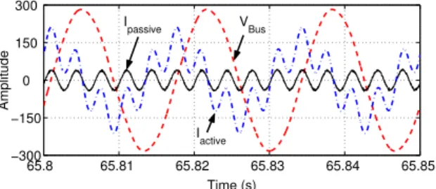
65.8 65.81 65.82 65.83 65.84 65.85 −300
−150 0 150 300
Time (s)
Amplitude
VBus Ipassive
I
active
Figure 16: Instantaneous performance of the shunt hybrid filter for phase A.
6 CONCLUSIONS
Besides limiting the passive filter currents, the series hybrid filter also improves the quality factor of the filter when the nominal current is not achieved. Other important advantages of this topology are its small rated power circuit and the ab-sence of matching transformers.
The results with the shunt hybrid filter presented its good per-formance to compensate the overcurrent in the passive filters and its effectiveness to improve the THD of the 345 kV bus where the active filter is installed. A matching transformer is necessary in this case.
The authors continues to develop researches focused on mul-tilevel structures for high power systems. In the future, it is intended to simulate the proposed hybrid filters in the com-plete digital model of the Ibiúna system.
REFERENCES
F. Z. Peng, J. W. Mckeever, D. J. A. (1997). Cascade
mul-tilevel inverters for utility applications, Proc. of the
IEEE International Conference on Industrial Electron-ics, Control, and Instrumentation, Vol. 2, New Orleans, pp. 437–442.
H. Fujita, T. Yamasaki, H. A. (2002). A hybrid active fil-ter for damping of harmonic resonance in industrial
power systems,IEEE Transactions on Power
Electron-ics15(2): 215–222.
J. Rodrígues, J. S. Lai, F. Z. P. (2002). Multilevel inverters: A
survay of topologies, controls, and applications,IEEE
Transactions on Industrial Eletronics49(4): 724–738.
K. Satoh, M. Y. (2001). The present state of the art in
high-power semiconductor devices,Proceedings of the IEEE
89(3): 813–821.
P. Jintakosonwit, H. Fujita, H. A. S. O. (2003).
Analy-sis and design of an active power filter to cancel har-monic currents in low voltage electric power
distribu-tion systems,IEEE Transactions on Industry
Applica-tions39(2): 556–564.
Plaisant, A. and Reeve, J. (1999). An active filter for ac har-monics from hvdc converters - basic concepts and
de-sign principles,Proc. of The IEEE Power Engineering
Society Summer Meeting, Vol. 1, Alberta, pp. 395–400.
Watanabe, E. H. and Aredes, M. (2002). Power consider-ations on shunt/series current and voltage condition-ers,Proc. of the 10th International Conference on Har-monic and Quality of Power, Vol. 2, Rio de Janeiro, pp. 595–600.
Y. Liang, C. O. N. (2000). A power-line conditioner based on flying-capacitor multilevel voltage-source converter
with phase-shift spwm,IEEE Transactions on Industry