o
ABSTRACT: Scientists at the laboratory of Força
Aérea Brasileira (FAB) have demonstrated experimentally that laser-induced “air spikes” (DEAS) may reduce effectively both total vehicle drag and heating at hypervelocities. Now, we apply the Rayleigh low to directly determine the degree of reduction in vehicle drag and convective heat lux into the airframe of a hypersonic blunt-body when laser energy is added upstream of the light path. Our numerical indings are in accordance with the physical trends observed in our previous hypersonic laser-induced DEAS experiments.
KEYWORDS: Laser, Flow control, Hypersonic, Rayleigh low.
Calculation of The Vehicle Drag and Heating
Reduction at Hypervelocities with
Laser-Induced Air Spike
Israel da Silveira Rêgo1, Paulo Gilberto de Paula Toro2, Marco Antonio Sala Minucci3,
José Brosler Chanes Júnior2, Felipe Jean da Costa4, Antonio Carlos de Oliveira2
INTRODUCTION
Hypersonic technologies now being developed by a few countries, including Brazil, could within two or three decades yield limitless possibilities for air and space travel. In particular, hypersonic light poses numerous engineering challenges involving many more structural diiculties due to severe heating and dynamic loads, new materials and structures for airframe, predictive models for hypersonic low, advanced control techniques for hypervelocity lights, new types of airbreathing propulsion systems and proper aerodynamic integration of both airframe and propulsion systems (Heiser and Pratt, 1994).
he Directed-Energy Air Spike (DEAS) is a promising technique for hypersonic light control, according to which an air spike is induced upstream in relation to the light path serving to reduce the vehicle drag and to lower heat transfer into the airframe (Myrabo and Raizer, 1994). Air spike production is obtained through many means, including electric arcs (Toro, 1998; Minucci et al., 2000), microwaves (Myrabo and Lewis, 2009) and laser beams (Minucci et al., 2005; Oliveira et al., 2008; Oliveira, 2008; Salvador et al., 2006).
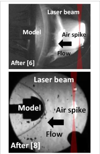
A series of experiments on the concept of hypersonic laser-induced DEAS was performed at the Aerothermodynamics and Hypersonic Laboratory Henry T. Nagamatsu, at Instituto de Estudos Avançados (IEAv), in São José dos Campos, Brazil, conclusively proving that air spikes do work for enhancing light performance (Minucci et al., 2005; Oliveira et al., 2008; Oliveira, 2008; Salvador et al., 2006). Figure 1 shows the historic hypersonic laser-induced DEAS experiments at the IEAv.
1.Universidade Federal do ABC – Santo André/SP – Brazil 2.Instituto de Estudos Avançados – São José dos Campos/SP – Brazil 3.Vale Soluções em Energia – São José dos Campos/SP – Brazil 4.Instituto Tecnológico de Aeronáutica – São José dos Campos/SP – Brazil
Author for correspondence:Israel da Silveira Rêgo | Rua Santa Adélia, 166 – Bangu | CEP 09210-170 Santo André/SP – Brazil | E-mail: [email protected]
However, the LSD wave is not taken into account for sake of simplicity. Thus, the changes in the one-dimensional flow occurring inside the control volume in Fig. 2 is caused only by the heat added to the hypersonic airflow by the intense beam of laser radiation without the presence of any shock wave.
he governing equations of the hypersonic airlow are continuity, momentum and energy, written as follows (Anderson, 2003):
ρ1V1 = ρ2V2 (1)
p1 +ρ1V12 = p2 +ρ2V22 (2)
h1 + + qL = h2 +
2 2
V1
2 2
V2 (3)
hey say that mass is conserved (Eq. 1), force equals time rate of change of momentum (Eq. 2), and energy is also conserved (Eq. 3). Note that Eq. 2 neglects body forces and viscous stresses, and Eq. 3 does not include shat work and work done by viscous stresses, but takes into account the amount of laser energy added by unit of mass, qL. Since conditions in region 1 are known, for a given qL these equations, along with the appropriate equations of state and the speciic case of a calorically perfect gas, can be analytically solved for conditions in region 2. Although the airlow is hypersonic, we assume that the air is calorically perfect, that is, air with constant speciic heats and unchangeable composition. Note that conditions in regions 1 and 2 correspond to freestream conditions of the hypersonic airlow before and ater adding the laser energy.
Figure 1. IEAv experiments on hypersonic laser-induced DEAS concept.
Freestream Bow shock
Model
Shock layer
ρ1 qL
T1
M1 ρ2
T2
M2 ρ0SL
2 1
p01 p2
Laser Beam
Figure 2. Rectangular control volume for one-dimensional airlow with laser energy addition.
Now, we will use the Rayleigh low to investigate the laser-induced DEAS in hypersonic airlow in a manner that the degree of reduction in vehicle drag and convective heat lux can be easily determined. he methodology is validated by comparison with our previous experimental indings (Minucci et al., 2005; Oliveira et al., 2008; Oliveira, 2008; Salvador et al., 2006).
METHODOLOGY
o
RAYLEIGH FLOW
he analytical relations for the one-dimensional hypersonic low with laser energy addition can be given as follows (Anderson, 2003):
qL = cp (T02− T01) (4)
p2 = 1 + γM1
p1 = 1 + γM2 2
2 (5)
T2 = M2 1+ γM1
T1 = M1 1+ γM2
2 2 2
2 (6)
2 = M1 1+ γM2
1 = M2 1+ γM1
2 2
2 ρ
ρ
(7)
T02 T2 1+ (γ-1)M2 / 2
T01 T1 1+ (γ-1)M1 / 2 2
2
=
(8)
p02 1+ γM2 1+ (γ-1) M2 / 2
P01 1+ γM1 1+ (γ-1) M1 / 2
2
γ
2 2
2
=
γ-1
(9)
S2 − S1 = cp ln T2 − R ln T1
P2
P1 (10)
hey are the basic relations, which are valid for any low with heat addition or removal, known as Rayleigh low relations. Table 1 shows the variation in hypersonic low quantities produced by laser energy addition.
SONIC FLOW CONDITION AND RAYLEIGH TABLE A methodology for the solution of Rayleigh low relations is now outlined as follows. All conditions in region 1 are experimentally known. Also, the amount of laser energy added by unit of mass is experimentally estimated a priori. herefore, given qL, T02 can be obtained from Eq. 4. Now, instead of inding the solution of Eq. 8 for M2 by trial and error, for convenience of calculation we use sonic low as a reference condition and Rayleigh table for air, which we will explain briely here. Let M1=1. hen, the corresponding low properties are denoted by p1= p* , T1= T*, r1= r*, p01= p*01, and T01= T*01 . he low properties at any other value of M are then obtained by inserting M1= 1 and M2= M into Eqs. 5 to 9, given (Anderson, 2003):
p2 1 + γ p* 1 + γM=
(11)
T T* =
1 + γ 1 + γM2
M2
2
(12)
=
1 + γ 1 + γM2
M2
1
ρ
ρ* (13)
=
(1 + γM2)
(1 + γ) M2
2 +( γ-1) M2
T0
T*0 2 (14)
p0 1+ γ 2 + (γ-1)M
P*0 1+ γM 1+ γ
2 γ
2
=
γ-1
(15)
Equations 11 to 15 are tabulated as a function of M for air in appendix A.3 of Anderson’s book (Anderson, 2003). Here, the reference sonic conditions p*, T*, ρ*, p0*, and T0*, are those in the one-dimensional low that would exist if enough laser energy is added to achieve Mach 1. he reference sonic conditions achieved when enough laser energy is added to bring the low to Mach 1 are exactly the same, no matter whether the laser energy is added as q*L1, downstream of region 1 or as q*L2 downstream of region 2. his is why Eqs. 11 to 15 are simply reference quantities that are ixed for a given airlow with heat addition. With this concept, we can easily obtain M2. Consequently, any condition in region 2 is calculated directly with Eqs. 5 to 10.
REDUCTION IN DRAG AND HEATING
For the aerodynamic application addressed here, both drag and convective heat lux to the vehicle moving through the hypersonic airlow, before and ater adding laser energy upstream of the light path, should be compared separately. he total drag D and the convective heat lux q. are proportional to ρV2 and ρV3, respectively (Anderson, 2007). Hence:
Quantity Variation for qL>0 and M1>1
Mach number M2<M1
Velocity u2<u1
Temperature T2>T1
Pressure p2>p1
Total pressure p02<p01
Total temperature T02>T01
Entropy s2–s1>0
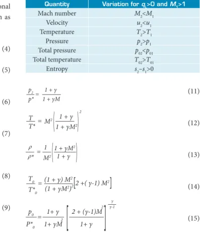
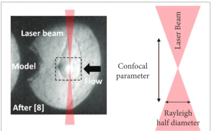
Fig. 3. Note that the laser spot size is not exactly the size of the laser– induced air-spike, which grows rapidly over time. Fortunately, the confocal parameter and the Rayleigh half diameter depend only on the focal length of the lens (200 cm) employed and the laser wavelength (10.6 µm). Hence, the laser spot size can be obtained and, consequently, the laser energy added by unit of mass.
Before adding the laser energy, the hypersonic airlow is isentropic (region 1). Hence, from isentropic airlow properties in appendix A.1 of Anderson’s book (Anderson, 2003), for a given M1 we obtain T01/T1 and then T01 (once T1 is known beforehand). Eq. 4, assuming that the speciic heat capacity at constant pressure of air is constant (1004,5 J/kg.K), gives T02. Now, from the Rayleigh airlow table in appendix A.3 of Anderson’s book (Anderson, 2003), for a given M1 we have p1/p*, T1/T*, and T01/T0*. Let us rewrite T02/T0* as (T02/T01) (T01/T0*).
With this and, again, from the Rayleigh airlow table, for a given T02/T0* we obtain directly M2. Now, we calculate the reduction in stagnation pressure, i.e., the ratio between the stagnation pressure ater and before laser-induced air spike. he stagnation pressure before adding laser energy is obtained directly from normal shock relations (since M1 and p1 are previously known). To obtain the stagnation pressure ater adding laser energy, we irst need to determine p2 (see Fig. 2). To do so, = ρ2
ρ1 D2 D1
T2 T1
M2 M1 2
(16)
= ρ2 ρ1 q2
q1
T2 T1
M2 M1 3 3/2
•
•
(17)
We have used Eqs. 16 and 17 along with the sonic low condition and Rayleigh tables to discuss theoretically the aerodynamic applicability of laser-induced DEAS to control vehicle drag and heating at hypervelocities. he main advantage of this methodology is simplicity, which allows us to easily compare and contrast the numerical indings with the facts observed in our hypersonic laser-induced DEAS experiments (Minucci et al., 2005; Oliveira et al., 2008; Oliveira, 2008; Salvador et al., 2006).
RESULT AND DISCUSSION
CALCULATION OF DRAG REDUCTION
Table 2 lists our experimental data on laser energy addition in hypersonics (Oliveira, 2008; Salvador et al., 2006), which will be input into the calculations of the reduction in drag and heating. he drag reduction on the blunt body occurs mainly because of the decrease in p02 ater air spikes are induced by the laser beam upstream in relation to the light path. A measure is done indirectly by measuring the stagnation pressure in the shock layer behind the bow shock, that is, p0SL . In fact, the magnitude of p0SL decreases ater adding laser energy as shown in Table 2. hus, before calculating drag reduction, we will calculate the reduction in stagnation pressure, and then compare it to the experimental one.
he amount of laser energy added by unit of mass is deined as the ratio between the rate of laser energy, i.e., laser power and mass low ρVA, in which A is the laser spot size. As a measure of A, we multiply the confocal parameter and the Rayleigh half diameter (assuming a Gaussian laser beam) (Siegman, 1986), as shown in
Enthalpy [unit]
T1*
[K]
ρ1*
[kg/m3] Mach
Speed [km/s]
Laser power [MW]
Stagnation pressure reduction [%]
Low 132 0.1019 6.9 1.6 1.35 31
Low 132 0.1019 6.9 1.6 1.85 43
Low 132 0.1019 6.9 1.6 1.77 48
High 1079 0.0093 5.7 3.4 1.5 54
High 1079 0.0093 5.7 3.4 1.7 45
Table 2. IEAv data on laser energy addition in hypersonics.
* Calculated from Hypersonic Shock Tunnel Real Gas (HSTR) software (Oliveira, 2008)
Figure 3. Illustration of laser spot size to estimate the laser energy per unit of mass.
Rayleigh half diameter Confocal
parameter
L
as
er B
ea
o
we rewrite p2 as (p2/p*) (p*/p1) p1, in which p2/p* and p*/p1 are obtained directly from the Rayleigh airlow table for M2 and M1 respectively. Also, the stagnation pressure ater adding laser energy is obtained directly from normal shock relations (since M2 and p2 were obtained previously). Figure 4 shows the reduction in total pressure against laser power for low and high enthalpy lows.
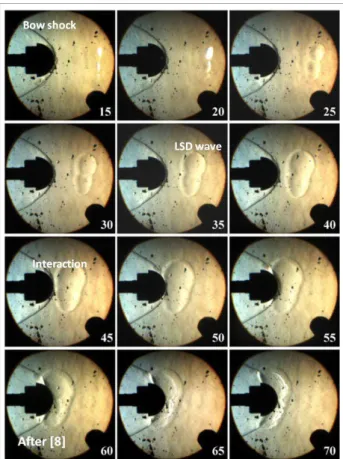
Linear its represent trends in the data. When there is no laser energy addition, the reduction in total pressure is null. Note that the laser-induced DEAS is more efective to reduce the total pressure as the laser power increases, which is in accordance with Eq. 9. Also, the rate and degree of total pressure reduction is more modest for calculations in comparison with experiments. his is because our methodology assumes no interaction between the bow shock ahead of the blunt body and the LSD wave generated (see Fig. 5), which lowers somehow the strength of the curved bow shock.
he drag reduction is calculated as follows. With the Rayleigh airlow table, for a given M2 we obtain p2/p* and T2/T*. Let us rewrite p2/p1 and T2/T1 as (p2/p*) (p*/p1) and (T2/T*) (T*/T), respectively. hus, p2/p1 and T2/T1 are both obtained. he supersonic solution of the Rayleigh low implies that both freestream density and temperature will increase while the Mach number will decrease as the laser beam heats the freestream. Finally, with Eq. 16 we calculate D2/D1, as shown in Fig. 6. Linear its represent trends in the data. When there is no laser energy addition, the reduction in drag is null. Calculations show that laser-induced DEAS is more efective to reduce vehicle drag when laser power and low enthalpy (low speed) increase. Also, the rate of drag reduction is more modest for low enthalpy. Experimental data on drag
0.00
0.00 0.50
Laser power [MW]
1.00 1.50 2.00 0.10
0.20 0.30 0.40 0.50 0.60 0.70 0.80 0.90 1.00
St
ag
n
at
io
n p
res
sur
e r
ed
uc
tio
n
Low enthalpy experiments Low enthalpy calculations High enthalpy experiments High enthalpy calculations Linear (Low enthalpy experiments) Linear (Low enthalpy calculations) Linear (High enthalpy experiments) Linear (High enthalpy calculations)
Figure 4. Reduction in stagnation pressure versus laser power for low and high enthalpy lows.
Figure 5. Interaction between bow shock and LSD wave in hypersonic low.
0.00
0.00 0.50
Laser power [MW]
1.00 1.50 2.00 0.10
0.20 0.30 0.40 0.50 0.60 0.70 0.80 0.90 1.00
R
ed
uc
tio
n in dra
g Low enthalpy calculations
High enthalpy calculations
Linear (Low enthalpy calculations)
Linear (High enthalpy calculations)
Figure 6. Reduction in vehicle drag versus laser power for low and high enthalpy lows.
efectively to reduce the convective heat lux, that is, increasing qL forces M2 → 1 (chocked low) and thereby decreasing the ratio. Again, note that the rate and degree of heating reduction is more modest for calculations in comparison with the experiments (Salvador et al., 2006) due to the fact that our methodology neglects the interaction between bow shock and LSD wave.
Our previous hypersonic DEAS experiments revealed that the distance between the blunt body and the laser-induced air spike, as well as the angle of incidence of the laser beam relative to the low direction, inluence the degree of reduction in drag and heating (Oliveira et al., 2008; Salvador et al., 2006). However, our calculations do not consider this fact for the sake of simplicity.
CONCLUSIONS
he hypersonic age of air and space travel will be a reality by 2030. Since 1992, Brazil seeks hypersonic technologies such as scramjet engines, waverider design and advanced techniques for controlling airlow at hypervelocities. We applied the Rayleigh low relations and sonic low conditions to determine the degree of reduction in vehicle drag and heating at hypervelocities when laser energy is added to the freestream. Calculations show the same physical trends observed in experiments, clearly indicating that laser-induced air spikes are in fact beneicial to enhance the light performance of hypersonic vehicles.
REFERENCES
Anderson J.D., 2007, “Introduction to Flight”, 6th edition, Science Engineering & Math, pp. 257-263.
Anderson J.D., 2003, “Modern Compressible Flow: With Historical Perspective”, 3rd edition, McGraw-Hill, pp. 102-111.
Heiser, W.H. and Pratt, D.T., 1994, “Hypersonic Airbreathing Propulsion”, 5th edition, AIAA Education Series, pp. 1-27.
Minucci M.A.S. et al., 2000, “Experimental Investigation of an Electric
Arc Simulated “Air-Spike” in Hypersonic Flow”, AIAA paper 00-0715, 38th Aerospace Sciences Meeting & Exhibit, Reno.
Minucci M.A.S. et al., 2005, “Laser-Supported Directed-Energy ‘Air
Spike’ in Hypersonic Flow”, Journal of Spacecraft and Rockets, Vol. 42, No. 1, pp. 51-57.
Myrabo L.N. and Lewis J., 2009, “Lightcraft Flight Handbook: LTI-20”, Apogee Books, pp. 49-66.
Myrabo L.N. and Raizer Y.P., 1994, “Laser Induced Air-spike for Advanced Transatmospheric Vehicles”, AIAA paper 94-2451, 25th AIAA Plasmadynamics and Laser Conference, Colorado.
Oliveira A.C., 2008, “Investigação Experimental da Adição de Energia por Laser em Escoamento Hipersônico de Baixa Densidade”, PhD Thesis (in Portuguese), INPE, São José dos Campos.
Oliveira A.C. et al., 2008, “Bow Shock Wave Mitigation by
Laser-Plasma Energy Addition in Hypersonic Flow”, Journal of Spacecraft and Rockets, Vol. 45, No. 5, pp. 921-927.
Salvador I.I. et al., 2006, “Experimental Analysis of Heat Flux to
a Blunt Body in Hypersonic Flow with Upstream Laser Energy Deposition - Preliminary Results”, 4th International Symposium on Beamed Energy Propulsion, AIP Conference Proceedings, Vol. 830, pp. 163-171.
Siegman A.E., 1986, “Lasers”, 1st edition, University Science Books, pp. 663-679.
Toro, P.G.P., 1998, “Experimental Pressure and Heat Transfer Investigation over a Directed-Energy Air Spike Inlet at Flow Mach Number of 10 to 20, Stagnation Temperature of 1000K, with Arc Power up to 127 kW”, PhD Thesis, Rensselaer Polytechnic Institute, Troy.
CALCULATION OF HEAT REDUCTION
he reduction in convective heat lux to the airframe of the blunt, body occurs mainly due to the deceleration of the freestream, as observed in our DEAS experiments. Also, our calculations show a deceleration of the freestream when the laser beam heats the hypersonic low. he reduction in convective heat lux is calculated as drag reduction, except for the fact that now we use Eq. 17. Figure 7 shows heating reduction as function of laser power with increasing enthalpy. Calculations show that laser-induced DEAS is more efective to reduce heating to the blunt-body airframe as both laser power and low enthalpy increase. his is because of the term (M2/M1)3 in Eq. 17, which contributes
Figure 7. Reduction in heating versus laser power for low and high enthalpy lows.
0.00
0.00 0.50
Laser power [MW]
1.00 1.50 2.00 0.10
0.20 0.30 0.40 0.50 0.60 0.70 0.80 0.90 1.00
R
ed
uc
tio
n in h
ea
t l
ux
Low enthalpy calculations
High enthalpy calculations
Low enthalpy experiments
Linear (Low enthalpy calculations)
Linear (High enthalpy calculations)