DOI: http://dx.doi.org/10.1590/2446-4740.08916 Volume 33, Number 2, p. 97-104, 2017
Introduction
Experimental studies with the spine are usually performed with anatomical parts of elderly individuals. Another alternative is the use of animal spines from monkeys or pigs (Kouwenhoven et al., 2007). However, vertebral deformity such as adolescent idiopathic scoliosis (AIS) is not found in quadruped animals. It affects young people who have yet to reach complete bone maturity (Castelein et al., 2005). The availability of a young spine for experimental studies is extremely rare.
Computer modeling is contributing to solving to complex problems that usually do not have analytical
solutions or that offer no possibility of experimental study. Many phenomena can be described in terms of partial differential equations, and the inite element method (FEM) is a numerical approach with which these equations can be solved in approximate terms (Fish and Belytschko, 2009). In recent decades, computational studies using FEM have successfully analyzed biomechanical systems and have made important contributions to understanding the mechanical behavior of the human spine (Cheng et al., 2010; Dong et al., 2013; Fok et al., 2010; Ghista et al., 1988; Kakol et al., 2003; Lan et al., 2013; Lodygwski et al., 2005; Meijer et al., 2010; Rajasekaran et al., 2011; Teo and Ng, 2001; Travert et al., 2011; Tyndyk et al., 2007; Van Der Plaats et al., 2007; Wierszycki et al., 2006; Xia et al., 2003). Over time, different geometric models have been used, including everything from simple versions containing beam elements, represented by interconnected cylinders and bars (Ghista et al., 1988), to more comprehensive volumetric models of the spine.
The irst step in computer analysis by FEM is generating the structure to be analyzed, which is represented in a three-dimensional (3D) geometric virtual environment (computer-aided design: CAD). In general, biomedical research is conducted with complex geometric structures
Three-dimensional geometric model of the middle segment of the
thoracic spine based on graphical images for inite element analysis
Rozilene Maria Cota Aroeira
1, Antônio Eustáquio de Melo Pertence
2, Daniel Takanori Kemmoku
3,
Marcelo Greco
1*
1Department of Structural Engineering, Federal University of Minas Gerais – UFMG, Belo Horizonte, MG, Brazil. 2Department of Mechanical Engineering, Federal University of Minas Gerais – UFMG, Belo Horizonte, MG, Brazil. 3Tridimensional Technology Division, Renato Archer Information Technology Center, Campinas, SP, Brazil.
Abstract Introduction: Biomedical studies involve complex anatomical structures, which require speciic methodology
to generate their geometric models. The middle segment of the thoracic spine (T5-T10) is the site of the highest incidence of vertebral deformity in adolescents. Traditionally, its geometries are derived from computed tomography or magnetic resonance imaging data. However, this approach may restrict certain studies. The study aimed to generate two 3D geometric model of the T5-T10 thoracic spine segment, obtained from graphical images, and to create
mesh for inite element studies. Methods: A 3D geometric model of T5-T10 was generated using two anatomical
images of T6 vertebra (side and top). The geometric model was created in Autodesk Maya 3D 2013, and the
mesh process in HiperMesh and MeshMixer (v11.0.544 Autodesk). Results: The T5-T10 thoracic segment model
is presented with its passive components, bones, intervertebral discs and lavum, intertransverse and supraspinous
ligaments, in different views, as well as the volumetric mesh. Conclusion: The 3D geometric model generated from
graphical images is suitable for application in non-patient-speciic inite element model studies or, with restrictions,
in the use of computed tomography or magnetic resonance imaging. This model may be useful for biomechanical studies related to the middle thoracic spine, the most vulnerable site for vertebral deformations.
Keywords Graphical modeling, Anatomic models, Thoracic spine, Finite element method.
This is an Open Access article distributed under the terms of the Creative Commons Attribution License, which permits unrestricted use, distribution, and reproduction in any medium, provided the original work is properly cited.
How to cite this article: Aroeira RMC, Pertence AEM, Kemmoku DT, Greco M. Three-dimensional geometric model of the middle segment of the thoracic spine based on graphical images for finite element analysis.
Res Biomed Eng.2017; 33(2):97-104. DOI: 10.1590/2446-4740.08916.
*Corresponding autor: Escola de Engenharia, Universidade Federal
de Minas Gerais – UFMG, Avenida Antônio Carlos, 6627, Sala 4127, Pampulha, CEP 31270-901, Belo Horizonte, MG, Brazil. E-mail:
requiring specific methodology to generate their geometric models. This geometry can be captured and portrayed using a variety of methods, including laser scans, computer drawings (CAD), X-rays in multivision, or biplanar radiographic images (Dumas et al., 2005; 2008; Humbert et al., 2009; Kumar et al., 2016; Li et al., 2009; Novosad et al., 2004), magnetic resonance imaging (MRI), and computed tomography (CT) (Panagiotopoulou, 2009). The most widely used technique that allows 3D geometrical recognition of the human anatomy is based on CT and MRI. The advantage of this methodology is that tomographic images can accurately reproduce bone geometry and generate custom templates. However, the high ionizing radiation index of CT, radio frequencies and electromagnetism of NMR imaging, and the high cost make them unsuitable for acquiring geometric models for non-customized studies (El Masri et al., 2012). Moreover, these are tests performed with the patient in the supine position, while the upright position is a prerequisite to ensure accurate reproduction of morphological alterations in vertebral deformities (Wang et al., 2014). On the other hand, the biplane X-ray reconstruction method enables image acquisition in a standing position, and is also ionizing technique (Dumas et al., 2005).
Geometric modeling using 3D graphics may be an alternative to these techniques, for the biomechanics of non-customized studies. Advanced computer graphics and digitization software allow the study of skeletal muscle architecture. This methodology has been used to build systems that use virtual reality as the underlying technology to assist in educational and medical studies (Rosatelli et al., 2008). Several programs, such as 3ds Max, Blender, Maya, and Lightware, enable organic modeling from graphical images. This graphical modeling can be performed using two methods, namely, box modeling and surface tools. In box modeling, a shape is constructed from a solid object (cube, sphere, or cone), the surfaces of which are divided gradually, adding volume to the object. In surface tools, also denominated the spline network, an object is generated by the constructing a network of lines that are covered by a surface to form the object (Riddell, 2004). The methods are different with respect to the formation of elements in a polygonal mesh. In general, organic forms require a large number of polygons to be appropriately expressed. Rosatelli et al. (2008) used Maya 3D modeling to study the architectural parameters of the lumbar multiidus muscles such as iber length and angulation, tendon length, and iber volume. Hermenegildo et al. (2014) studied anatomical variations in the suprascapular nerve in cadavers, and represented them through Maya 3D modeling. However, no study has been found in the literature that uses Maya software to generate 3D geometry with the speciic purpose of FEM analysis.
There are a signiicant number of 3D models of the spine available in the literature. However, some studies may require morphological variations of a same anatomical model, such as changing thoracic kyphosis angles, which are not speciied in the literature. These morphological changes may require the creation of speciic 3D models for each study.
The aims of this study were: 1) to develop two geometric 3D models for the T5–T10 thoracic segment of an adolescent, showing kyphosis and absence of kyphosis, from graphical images; 2) Generate a inite element mesh from the geometry.
Methods
The software selected for geometric modeling was Autodesk Maya 3D 2013, developed by ALIAS in 1998 and acquired by Autodesk in 2006. It enables the expansion of functionalities through its built-in scripting language, Maya embedded language (MEL), or via non-proprietary languages such as Python and C++. The use of box modeling allows the accurate, realistic modeling of tissues, luids, and anatomical structures.
An SGI Workstation equipped with an Intel Xeon x5600 processor (2.80 GHz), 48 GB of Ram memory, and NVIDIA Quadro4000 video card, was used.
Creation of a 3D geometrical model
The creation of a 3D geometrical model of the middle segment of the thoracic spine begins by selecting the graphical image that most appropriately represents the anatomical components of a real spine. To that end, initial modeling was conducted based on images from a human anatomy atlas (Netter, 1997), which is a benchmark for academic studies. A prototype human spine made of polymer was used to design and detail the structures that were not visible in the graphics.
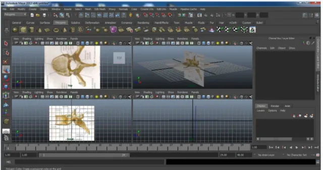
The basic graphical interface of Maya includes the left side of the menu screen, bar at the top, and central area of the desktop, which can be subdivided into front, side, top, and perspective views. Modeling can be conducted using several techniques, with selection depending on the type of model to be developed. The technique adopted here (box modeling), involves the deformation of an initial hexahedral region (primitive polygon). Modeling began with two graphical images of a thoracic vertebra, in this case, the top and sagittal views of the T6 vertebra. Following the creation of two polygonal plans, the images were imported, as shown in Figure 1.
The vertex extrusion process was employed and modeling followed until the limit of the graphical image of T6. The vertebral body was modeled by distinguishing the cortical bone shell on the outer portion of the vertebra and the inner portion of the cancellous bone. The thickness of the cortical shell varied for each vertebral body and was set to range from 1.5 to 2 mm. These values were based on the CT data obtained in the literature (Tyndyk et al., 2007). Due to the complexity and low thickness of the posterior part of the thoracic vertebrae, the cortical bone shell was not modeled
separately from the inner portion cancellous bone. For modeling the intervertebral discs, a vertex expansion and contraction process in three perspectives was applied, following the contour of lower vertebral plateau T6. The design followed the scaling parameters available in the literature (Panjabi et al., 1991) (Figure 3). The disc was modeled distinguishing the structures of the ibrous ring and pulpous nucleus, where the latter occupied 40% of the center of the disc (Figure 4). The main challenge in creating the geometric model lies in modeling the 10 facet joints. Since it is a small anatomic structure, approximately 1 cm high, detail in this region depended on the superior ability of the modeling process. The joint surfaces were considered to exhibit smooth concavity, in addition to apophyseal joint face angulation with a coronal plane, allowing the interline of these apophyses to be contained on a cylindrical surface with an axis at the center of the vertebral body (Meijer, 2011), and contact, without overlap, with the mesh generated. Accurate and symmetrical contact is necessary for a successful simulation with FEM. To achieve geometric symmetry, one of the hemiphases was replicated for all the structures of the inal model.
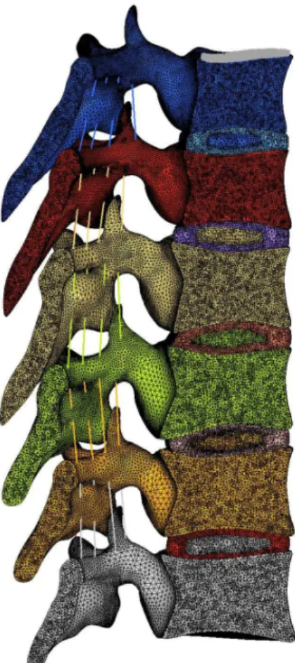
Subsequently, the T6 vertebra was resized to the geometric parameters of T5, T7, T8, T9, and T10 vertebrae based on quantitative studies of the 3D anatomy for thoracic vertebrae of Panjabi et al. (1991) (Table 1). A T5-T10 thoracic segment was created with a kyphosis angle of 31.25°, and, another, with rectiied kyphosis, see Figure 5.
Figure 1. MAYA screen image representing the import igure of the 6th thoracic vertebra in the top views, side and perspective, showing the
interaction between them.
Figure 4. Image in X-ray mode where the cortical and cancelous bone
of the vertebral body, and the ibrous ring and nucleus pulposus of the
intervertebral disc are observed.
Figure 3. MAYA screen image of complete modeling T7-T8 and its intervertebral disc.
Table 1. Vertebral dimensions [mm] - Transverse process width (TPW), End-plate depth upper (EPDu), End-plate depth lower (EPDl), Vertebral body
height (VBH), Pedicle width (PDW), Pedicle height (PDH), Spinous process length (SPL), End-plate width (EPW). Adapted from Panjabi et al. (1991).
Vertebra [mm] TPW EPDu EPDl VBH PDW PDH SPL EPW
T5 61.1 24.3 25.8 16.2 1.8 11.2 52.1 27
T6 61.3 26 26.9 17.4 2 12 53.8 28.2
T7 60.4 27.4 28.5 18.2 1.7 11.8 50.5 29.1
T8 59.9 27.9 29.4 18.7 1.9 12.5 52.8 30.5
T9 59.3 29.3 31 19.3 1.8 13.9 51.3 33
T10 58.4 30.5 31.6 20.2 1.8 14.7 49.3 35.4
Meshing procedure
After the geometric model was prepared, a 3D FEM model was generated using a speciic meshing procedure. This pre-processing was performed using the computer program HyperMesh version 14.0 (Troy, Michigan, USA). For more complex anatomical
Results
The 3D geometric model of the T5-T10 middle thoracic segment, based on graphical images, is presented with its passive components (bones, intervertebral discs and
lavum, intertransverse and supraspinous ligaments), in X ray, posterior frontal and sagittal views (Figure 5). It represents the anatomical features found in the actual structure of the middle thoracic spine. The model presented in the X-ray mode shows the distinct parts of the bone and intervertebral disc materials required for simulations with FEM. The Figure 6 presents the solid models of the six anatomically different thoracic vertebrae, included soft tissue such as intervertebral discs and spinal ligaments.
Discussion
The present study proposes a 3D geometric modeling of the adolescent thoracic spine segment, T5-T10, with kyphosis and absence of kyphosis, based on graphical images for inite element analysis. The T5-T10 segment is important for its vulnerability to spinal deformity in young people. Experimental studies have reported the importance of this thoracic segment in the initialization and progression of the spinal deformity adolescent idiopathic scoliosis (AIS) (Castelein et al., 2005; Kouwenhoven et al., 2007).
The use of anatomical parts of the human spine for experimental study is rare, primarily in young individuals. In some cases, computational models seem to be the only alternative. Thus, the generation of realistic spinal models is of great importance for computational analyses aimed at studying vertebral deformation in adolescents. A possible advantage in the use of computer graphics and digitization software, from graphic images, is the geometric control provided by the program, including solving contact problems, or reducing excessive detail before exporting the .stl mesh. Additionally, smaller and more complex anatomical structures, such as the cortical shell and facet joints, are below the resolution of techniques such as biplane or CT imaging and cannot be indicated in vivo due to high doses of radiation (El Masri et al., 2012).
There is no precedent in the literature regarding the generation of geometric models based on graphs for use in FEM simulations. A geometric model of the thoracic spine was created with proper orientation of the joint facets and geometry of adolescent vertebrae, in addition to pre-tension in the lavum and intertransverse ligaments. This model is a close representation of the actual model when compared to those depicting cylinders and bars (Ghista et al., 1988), typical volumetric models with a single mobile segment (Meijer et al., 2010) or volumetric models that omit the back portion of the vertebrae (Fok et al., 2010). In this respect, the model developed will enable a good quantitative assessment of displacement and rotation in the system, but may exhibit differences in stress and strain levels. An accurate Figure 5. Geometric model of the T5-T10 segment. Left to right: thoracic
kyphosis (31.24°) and absence of kyphosis.
model to evaluate stress and strain should consider the imperfections, porous, viscous and elastoplastic behavior of the material, considered complex parameters for accurate modeling. Additionally, the computational costs of complex models should also be taken into account.
A FEM study need to be constructed based on age-speciic biomechanical data. In a review study, Wang et al. (2014) reported that all the models surveyed used material and biomechanical data derived from adults. According to the authors, there is little biomechanical information concerning young vertebral columns owing to the dificulty in obtaining anatomical parts of the human spine from fresh cadavers. This issue was a challenge for this study. The scarcity of studies that reference the modulus of elasticity of the vertebrae tissues of younger individuals varies greatly with regard to values. Another challenge is the anatomical complexity of the human thorax, where the thoracic spine is located. It is known that the vertebral thoracic segment is encased in a closed system composed of bones from the rib cage, internal thoracic organs, and a complex system of fascias and muscles, the action of which increases the critical load and, consequently, vertebral stability. However, the complexity of the structure and the diversity in the orientation of muscular actions makes it dificult to include in the study. Few computational models include the ribs and posterior elements of the spine. According to Van Der Plaats et al. (2007), improving the model by incorporating the ribs and muscles is a major challenge to be overcome. However, the comparison between two different positions of the same model allows reaching relevant conclusions concerning the structural behavior of the adolescent thoracic segment.
In an FEM simulation using the geometric model proposed here, tetrahedral linear elements were used due to software limitations in generating the mesh of quadratic elements. To compensate for this limitation, we opted to control the mesh by increasing the density of elements in regions where more complex behavioral stress are assumed.
Although not included among the objectives of this paper, some preliminary results of the analysis with the FEM are presented. In an assessment of the rotational stability of vertebra under kyphosis of 31.24°, absence of kyphosis and ligament imbalance, it was found that the vertebra below the imbalance (T9) showed displacement similar to the deformity of scoliosis, in agreement with the study of Van Der Plaats et al. (2007), that is, an axial rotation of the vertebral bodies towards the convexity of the lateral curve. The facet joints were less requested in absence of kyphosis. Shear stresses values between 5 and 12.5 MPa were observed in the upper facets of T9; whereas the lower facets yielded values between 2.5 and 7.5 MPa, in kyphosis. In the case of absence of kyphosis under the same loading conditions, values of
7.5 MPa were observed in the upper facets of T9 and values close to zero were observed in the lower one. In addition, there were more pronounced vertebral rotations in the vertebral segments subject to imbalance of ligamentous forces, when compared to the spine with preserved kyphosis. The study demonstrated that the rotation of T8 in relation to T9 was greater in the case of absence of kyphosis and in the absence of an axial load (0.12° in kyphosis, and 0.22° in absence of kyphosis). These indings corroborate the hypothesis of Castelein et al. (2005), in which the authors describe a greater demand on the facet joints associated with greater eficiency in the containment of the rotation of a vertebra in relation to the adjacent vertebra. In an experimental study, Panjabi et al. (1976) evaluated the coeficient of rigidity and lexibility in the thoracic spine segments. The authors concluded that a thoracic functional unit is more lexible in traction than in compression. This could justify the greater rotational displacement of the T9 vertebra in this study when the axial load was removed. These indings contribute to the search for preventive actions of adolescent idiopathic scoliosis. The models analyzed in the study were sensitive to the action of loads on the spinal structures. This may have important clinical implications, such as the association of the spinal morphology of children and adolescents and the risk of vertebral deformation and spinal damage. Considering the complexity of biological structures and risks involving in vivo studies, the continuous improvement of computational modeling techniques using FEM is relevant.
The results obtained in this study reveal a versatile methodology able to vary the parameters of the structures described, such as using data from the 10-year-old girl spine geometry obtained from Meijer (2011) studies, or vary the morphology of a particular structure. Moreover, it exhibits good graphic quality and allows visualization of models in different perspectives. Other models for different populations and age groups, and different morphologies should be proposed. The use of three images, in three planes, likely increased the quality of the inal model generated by graphical images. Further studies are needed to improve alternative geometric modeling methods to MRI and CT, especially for application in non-patient-speciic inite element model studies.
Acknowledgements
References
Castelein RM, Dieën JH, Smit TH. The role of dorsal shear forces in the pathogenesis of adolescent idiopathic scoliosis:
a hypothesis. Medical Hypotheses. 2005; 65(3):501-8.
PMid:15913901. http://dx.doi.org/10.1016/j.mehy.2005.03.025.
Cheng FH, Shih SL, Chou WK, Livic L, Sung WH, Chen CS. Finite element analysis of the scoliosis spine under different loading conditions. Bio-Medical Materials and Engineering.
2010; 20(5):251-9. PMid:21084737.
Dong L, Li G, Mao H, Marek S, Yang KH. Development and validation of a 10-year-old child ligamentous cervical spine
finite element model. Annals of Biomedical Engineering. 2013;
41(12):2538-52. PMid:23817769. http://dx.doi.org/10.1007/ s10439-013-0858-7.
Dumas D, Lafage V, Lafon Y, Steib JP, Mitton D, Skalli W. Finite
element simulation of spinal deformities correction by in situ
contouring technique. Computer Methods in Biomechanics and Biomedical Engineering. 2005; 8(5):331-7. PMid:16298855. http://dx.doi.org/10.1080/10255840500309653.
Dumas R, Blanchard B, Carlier R, Loubresse CG, Le Huec J-C,
Marty C, Moinard M, Vital J-M. A semi-automated method using interpolation and optimisation for the 3D reconstruction of the spine from bi-planar radiography: a precision and accuracy
study. Medical & Biological Engineering & Computing. 2008; 46(1):85-92. PMid:17874152. http://dx.doi.org/10.1007/ s11517-007-0253-3.
El Masri F, Sapin de Brosses E, Rhissassi K, Skalli W, Mitton
D. Apparent young’s modulus of vertebral cortico-cancellous
bone specimens. Computer Methods in Biomechanics and Biomedical Engineering. 2012; 15(1):23-8. PMid:21749276. http://dx.doi.org/10.1080/10255842.2011.565751.
Fish J, Belytschko T. Um primeiro curso em elementos finitos.
Rio de Janeiro: LTC; 2009.
Fok J, Adeeb S, Carey J. FEM simulation of non-progressive
growth from asymmetric loading and vicious cycle theory:
scoliosis study proof of concept. The Open Biomedical Engineering Journal. 2010; 4(1):162-9. PMid:21379393. http://
dx.doi.org/10.2174/1874120701004010162.
Ghista DN, Viviani GR, Subbaraj K, Lozada PJ, Srinivasan TM, Barnes G. Biomechanical basis of optimal scoliosis surgical-correction. Journal of Biomechanics. 1988; 21(2):77-88.
PMid:3350831. http://dx.doi.org/10.1016/0021-9290(88)90001-2.
Hermenegildo JA, Roberts SL, Kim SY. Innervation pattern of the suprascapular nerve within supraspinatus: a three-dimensional computer modeling study. Clinical Anatomy
(New York, N.Y.). 2014; 27(4):622-30. PMid:23649406. http:// dx.doi.org/10.1002/ca.22250.
Humbert L, De Guise JA, Aubert B, Godbout B, Skalli W. 3D
reconstruction of the spine from biplanar X-rays using parametric models based on transversal and longitudinal inferences. Medical
Engineering & Physics. 2009; 31(6):681-7. PMid:19230743.
http://dx.doi.org/10.1016/j.medengphy.2009.01.003.
Kakol W, Lodygowski T, Ogurkowska MB, Wierszycki M.
Are we able support medical diagnosis or rehabilitation of human vertebra by numerical simulation? In: Proceedings of
the 15th International Conference on Computer Methods in
Mechanics; 2003 June 3-6; Gliwice, Poland. 2003.
Kouwenhoven JWM, Smit TH, Van Der Veen AJ, Kingma I, Van Dieen JH, Castelein RM. Effects of dorsal versus ventral shear loads on the rotational stability of the thoracic spine. Spine. 2007; 32(23):2545-50. PMid:17978652. http://dx.doi.
org/10.1097/BRS.0b013e318158cd86.
Kumar S, Nayak KP, Hareesha KS. Improving visibility of stereo-radiographic spine reconstruction with geometric
inferences. Journal of Digital Imaging. 2016; 29(2):226-34. PMid:26537930. http://dx.doi.org/10.1007/s10278-015-9841-1.
Lan CC, Kuo CS, Chen CH, Hu HT. Finite element analysis
of biomechanical behavior of whole Thoraco-lumbar spine
with ligamentous effect. Changhua J Med. 2013; 11:26-41.
Li H, Leow WK, Huang CH, Howe TS. Modeling and measurement of 3D deformation of scoliotic spine 2D X-ray
images. Comput Anal Images Patterns. 2009; 57(2):647-54. http://dx.doi.org/10.1007/978-3-642-03767-2_79.
Lodygwski T, Kakol W, Wierszycki M. Three-dimensional
nonlinear finite element model of lumbar intervertebral disc.
Acta of Bioengineering and Biomechanics. 2005; 7:17-28. Meijer GJM, Homminga J, Hekman EE, Veldhuizen AG,
Verkerke GJ. The effect of three-dimensional geometrical changes during adolescent growth on the biomechanics of
a spinal motion segment. Journal of Biomechanics. 2010;
43(8):1590-7. PMid:20206933.http://dx.doi.org/10.1016/j. jbiomech.2010.01.028.
Meijer GJM. Development of a non-fusion scoliosis correction device numerical modelling of scoliosis correction [thesis]. Enschede: Universiteit Twente; 2011.
Netter FH. Atlas of human anatomy. 2nd ed. East Hanover:
Novartis; 1997.
Novosad J, Cheriet F, Petit Y, Labelle H. Three-dimensional
3-D reconstruction of the spine from a single X-ray image
and prior vertebra models. IEEE Transactions on Bio-Medical Engineering. 2004; 51(9):1628-39. PMid:15376511. http://
dx.doi.org/10.1109/TBME.2004.827537.
Panagiotopoulou O. Finite element analysis (FEA): applying an
engineering method to functional morphology in anthropology and
human biology. Annals of Human Biology. 2009; 36(5):609-23. PMid:19657767.http://dx.doi.org/10.1080/03014460903019879.
Panjabi MM, Brand RA Jr, White AA 3rd. Mechanical properties
of the human thoracic spine as shown by three-dimensional
load-displacement curves. J Bone Joint Surg. 1976;
58-A(5):642-52. PMid:932062.
http://dx.doi.org/10.2106/00004623-197658050-00011.
Panjabi MM, Takata K, Goel V, Federico D, Oxland T, Duranceau J,
Krag M. Thoracic human vertebrae: quantitative three-dimensional
anatomy. Spine. 1991; 16(8):888-901. PMid:1948374. http://
dx.doi.org/10.1097/00007632-199108000-00006.
Rajasekaran S, Natarajan RN, Babu JN, Kanna PR, Shetty AP, Andersson GB. Lumbar vertebral growth is governed by “chondral growth force response curve” rather than “Hueter-Volkmann Law”. Spine. 2011; 36(22):E1435-45. PMid:21343857. http://
Riddell D. MAYA para Windows e Macintoch. Maya 5 for
Windows and Macintosh. São Paulo: Pearson Makron Books; 2004.
Rosatelli AL, Ravichandiran K, Agur AM. Three-dimensional study of the musculotendinous architecture of lumbar multifidus and its functional implications. Clinical Anatomy (New York,
N.Y.). 2008; 21(6):539-46. PMid:18627104. http://dx.doi.
org/10.1002/ca.20659.
Teo EC, Ng HW. Evaluation of the role of ligaments, facets and disc nucleus in lower cervical spine under compression and sagittal moments using finite element method. Medical
Engineering & Physics. 2001; 23(3):155-64. PMid:11410380.
http://dx.doi.org/10.1016/S1350-4533(01)00036-4.
Travert C, Jolivet E, Sapin-de Brosses E, Mitton D, Skalli
W. Sensitivity of patient-specific vertebral finite element model from low dose imaging to material properties and
loading conditions. Medical & Biological Engineering & Computing. 2011; 49(12):1355-61. PMid:21927822. http:// dx.doi.org/10.1007/s11517-011-0825-0.
Tyndyk MA, Barron V, McHugh PE, O’Mahoney D. Generation
of a finite element model of the thoracolumbar spine. Acta
of Bioengineering and Biomechanics. 2007; 9(1):35-46.
PMid:17933103.
Van Der Plaats A, Veldhuizen AG, Verkerke GJ. Numerical
simulation of asymmetrically altered growth as initiation
mechanism of scoliosis. Annals of Biomedical Engineering. 2007; 35(7):1206-15. PMid:17415662. http://dx.doi.org/10.1007/
s10439-007-9256-3.
Wang W, Baran GR, Betz RR, Samdani AF, Pahys JM, Cahill
PJ. The use of finite element models to assist understanding and treatment for scoliosis: a review paper. Spine Deformity. 2014; 2(1):10-27. PMid:27927438. http://dx.doi.org/10.1016/j. jspd.2013.09.007.
Wierszycki M, Kakol W, Lodygowski T. Numerical complexity
of selected biomechanical problems. Journal of Theoretical
and Applied Mechanics. 2006; 44(4):797-818.
Xia T, Qiu Chon E, Teo WC. Finite element on kinematics
of the thoracic T10-T11 motion segment: assessment of the locus of instantaneous axes of rotation in the sagittal plane.