Abs tract
Three-dimensional bending and stress analyses of the rotating two-directional functionally graded annular/circular plates or disks have not been accomplished so far. This task is performed in the present paper, employing a finite element formulation with a C1 -continuity. Therefore, both transversely graded and radially-graded plates may be analyzed as special cases of the present research. Distribution of the transverse loads as well as coefficients of the elastic foundation may be non-uniform. Mixed stress-based and displacement-based edge conditions are considered to cover many practical applications. Compatible Hermitian elements are employed to develop a consistent formulation and avoid jumps in the stress components at the elements interfaces. In contrast to the very limited works presented for the rotating functionally graded circular plates so far, the transverse flexibility and the transverse stress components are also considered in the present research. Finally, influences of the material properties distribution, angular speed, geometric parameters, and the elastic foundation on distributions of the stress and displacement components are investigated for a variety of edge and boundary conditions and some design criteria are extracted.
Key words
Three-dimensional stress analysis, compatible finite element, two-directional functionally graded materials, rotating annular/circular plates and disks, elastic foundation.
Three-dimensional compatible finite element stress
analysis of spinning two-directional FGM annular plates
and disks with load and elastic foundation
non-uniformities
1 INTRODUCTION
Many engineering components may be modeled as rotating circular plates or disks. Some examples may be found in the power transmission systems, machining devises, circular saws, microwave or baking ovens, photographic facilities, support tables, turbo-machinery, and flywheel and centrifugal
M. S ha ri ya t* an d R. Mo ha mm ad ja ni
Faculty of Mechanical Engineering, K.N. Toosi University of Technology, Tehran 19991-43344, Iran.
Received 17 Jan 2012 In revised form 30 Nov 2012
∗
Author email addresses:
Latin American Journal of Solids and Structures 10(2013) 859 – 890
systems. Some of these components (e.g., the clutch or brake disks) may be supported by generally non-uniform elastic foundations that rotate with the assembly. On the other hand, the main ad-vantage of using the functionally graded materials (FGMs) is providing the capability of accurately monitoring changes of the local material properties to optimize the component strength. Therefore, achieving a uniform effective stress to strength ratio in the whole component can be an objective. Depending on the function of the component, it is possible to utilize one-, two- or three-directional distributions of the material properties.
Some researchers used the plate theories for bending analysis of the stationary FG circular plates. Axisymmetric bending and stretching of the functionally graded solid and annular circular plates was studied by Reddy et al. (1999) using the first-order shear deformation plate theory. Ma and Wang (2004) employed the third-order shear deformation plate theory to study axisymmetric bending of the functionally graded circular plates. Golmakani and Kadkhodayan (2011) studied axisymmetric nonlinear bending of an annular functionally graded plate using the finite difference technique.
Due to the contradictory assumptions used in the plate theories, their results may be inaccurate for many applications, especially for the thick plates or disks. Instead, results of the three-dimensional theory of elasticity are exact and more accurate. Assuming the material properties to vary in both transverse and radial directions, Nie and Zhong (2007) investigated axisymmetric bending of the two-directional functionally graded circular and annular plates based on the three-dimensional theory of elasticity using a semi-analytical method. Li et al. (2008a) obtained an elastic solution for axisymmetric bending of FGM circular and annular plates subject to polynomial loads of even order. The problem of a functionally graded, transversely isotropic, magneto–electro-elastic circular plate acted on by a uniform load is treated by Li et al. (2008b) based on the three-dimensional theory of elasticity. Yang et al. (2008) presented an analytical solution for bending of annular plates under uniform loadings. Lei and Zheng (2009) presented an exact solution for ax-isymmetric bending of functionally graded circular plates under elastically supported and rigid slip-ping edge conditions. Based on the three-dimensional theory of elasticity, Wang et al. (2010) inves-tigated axisymmetric bending of functionally graded circular plates subjected to Bessel function-type transverse loads using the direct displacement method.
Latin American Journal of Solids and Structures 10(2013) 859 – 890
Reviewing the literature reveals that very limited papers have been published on the two-directional functionally graded circular plates (Nie and Z. Zhong, 2007). Nie and Zhong (2010) investigated dynamic behavior of the two-directional FGM annular plates based on the three-dimensional theory of elasticity using the state-space method combined with the one three-dimensional differential quadrature method. Recently, some semi-analytical vibration and buckling solutions have been proposed by Alipour et al. (2010), Shariyat and Alipour (2011), and Alipour and Shari-yat (2011) for two-directional functionally graded circular plates resting on elastic foundations based on the shear-deformation plate theories and the differential transformation method (DTM). The above brief review reveals that three-dimensional bending and stress analysis of two-directional functionally graded annular/circular plates resting on elastic foundations has not been performed yet, even for the stationary plates. Some other novelties included in the present research are considering non-uniform distributions of both the transversely imposed load and the elastic coef-ficient of the foundation. Furthermore, a variety of the mechanical surface and edge conditions is considered. Moreover, the available finite element analyses (even those performed by NASTRAN,
ABAQUS, and ANSYS softwares), have been performed based Lagrangian (C0-continuous)
ele-ments. Present results are extracted employing compatible C1-continuous elements to avoid stress
discontinuities at the mutual boundaries of the elements. Effects of the material properties indices, geometric parameters, foundation stiffness, type of the non-uniform distributions of the transverse loads and the stiffness of the elastic foundation, and edge conditions on the bending behavior and stress distribution of the mentioned annular plates/disks are investigated through a parametric study and some design criteria are extracted.
2 THE GOVERNING EQUATIONS
2.1 Description of variations of the material properties
Consider a rotating annular two-directional functionally graded axisymmetric plate with inner radius a, outer radius b, and thickness h resting on an elastic foundation, as shown in Figure 1. In Figure 1, the radial and axial (transverse) coordinates are denoted by r and z, respectively. Gen-erally, both the transversely distributed load and stiffness of the elastic substrate/foundation may
vary with the radial coordinate r. The transverse coordinate z of the plate is measured from the
bottom surface of the plate and is positive upward. It is assumed that Young’s modulus E,
Pois-son’s ratioν, and the mass density ρ vary in both radial and transverse directions according to
exponential functions:
E r
( )
,z =E(
0,0)
e m 1z h+ n 1r b ⎛ ⎝⎜ ⎞ ⎠⎟ (1)ρ
( )
r,z =ρ(
0,0)
e m 2z h + n 2r b ⎛ ⎝⎜ ⎞ ⎠⎟ (2)v r
( )
,z =v(
0,0)
em3z
h+ n3r
b
⎛ ⎝⎜
⎞
Latin American Journal of Solids and Structures 10(2013) 859 – 890
where E
( )
0,0 , ρ(
0,0)
, and v( )
0,0 are the reference values corresponding to the coordinate origin(of a solid circular plate). m
i and ni (i=1,2,3) are indices of the material mixture and are
as-sumed to be temperature-independent.
Figure 1 Geometric parameters of a rotating two-directional functionally graded annular plate or disk resting on a non-uniform elastic foundation. The non-uniform transversely distributed loads and the edge conditions are not shown for the sake of clarity.
2.2 The finite element governing equations of the entire plate
Rectangular compatible Hermitian elements are used to discretize the plate. Since the loading and boundary conditions are assumed to be axisymmetric, only the cross section of the plate has to be discretized (Figure 2).
Figure 2 Discretization of the cross section of the plate.
The traditional finite element analysis softwares, e.g., NASTRAN, ANSYS, and ABAQUS,
generally use Lagrangian elements with C0-continuity (Garcia and Proença, 2007, Polat, 2010,
Latin American Journal of Solids and Structures 10(2013) 859 – 890
δ= u
w ⎧ ⎨ ⎪ ⎩⎪ ⎫ ⎬ ⎪ ⎭⎪=
H 0 ... 0
0 H ... 0 ... ... ... ... 0 0 ... H
⎡ ⎣ ⎢ ⎢ ⎢ ⎢ ⎤ ⎦ ⎥ ⎥ ⎥ ⎥
Λ(e)
=H(e)Λ(e)
(4)
where u and w are respectively the radial and transverse displacement components,
!
!
Λ
"e $is thevector of the nodal values containing the displacement parameters and their derivatives (Figure 2):
! !Λ
"e $T
= U1 U1,ξ U1,η U1,ξη ... W4 W4 ,ξ W4 ,η W4 ,ξη (5)
The natural coordinates ξ(−1≤ξ ≤1) and η(−1≤η ≤1) are in the radial and transverse
direc-tions, respectively and may be related to the global coordinates r and z as follows:
r=(m−1 / 2+ξ/ 2)Δr, z=(n−1 / 2+η/ 2)Δz (6)
where m and n are the element counters in the radial and transverse directions, respectively.
Therefore,
∂ ∂r=
∂ ∂ξ
∂ξ
∂r = 2 Δr
∂ ∂ξ,
∂ ∂z=
∂ ∂η
∂η
∂z = 2 Δz
∂ ∂η
dr=Δr 2
dξ, dz= Δz 2
dη
(7)
In Eq. (4) [26]:
!
!
!
H= H11 H21 H12 H22
Hij = H
0i
1
(ξ)H
0j
1
(η) H
1i
1
(ξ)H
0j
1
(η) H
0i
1
(ξ)H
1j
1
(η) H
1i
1
(ξ)H
1j
1
(η) ,i=1,2;j =1,2 (8)
where, each of i and j subscripts is the node number in the
ξ
andη
directions, respectively (1or 2):
!
!
H 01 1%ξ&=1
4
(
1−ξ)
2
%2+ξ&
H
02 1
%ξ&=1
4
(
1+ξ)
2
%2−ξ&
H
11 1
%ξ&=1
4
(
1−ξ)
2
%ξ+1&
H
12 1
%ξ&=1
4
(
1+ξ)
2
%ξ −1&
Latin American Journal of Solids and Structures 10(2013) 859 – 890
On the other hand, the strain components may be related to the displacement components as:
εr = ∂u
∂r , εθ= u
r , εz = ∂w
∂z , γrz = ∂u ∂z +
∂w
∂r (10)
or in a matrix form:
ε=dδ =dH(e)Λ(e)
(11)
where the superscript “(e)” denotes the element quantity and
εT = ε
r εθ εz γrθ , d= ∂ ∂r 0
1 r 0 0 ∂ ∂z ∂ ∂z ∂ ∂r ⎡ ⎣ ⎢ ⎢ ⎢ ⎢ ⎢ ⎢ ⎢ ⎢ ⎢ ⎢ ⎤ ⎦ ⎥ ⎥ ⎥ ⎥ ⎥ ⎥ ⎥ ⎥ ⎥ ⎥ (12) So that: δεT
= δΛ(e)
(
)
TdH(e)
(
)
T(13)
According to the generalized Hooke’s law, the stress-strain relation may be expressed as:
σ=dε − σ
T (14)
where:
σT = σ
r σθ σz τrθ ,
d= E(r,z) 1−2ν
( )
r,z⎡⎣ ⎤⎦⎡⎣1+ν
( )
r,z ⎤⎦1−ν
( )
r,z ν( )
r,z ν( )
r,z 0 ν( )
r,z 1−ν( )
r,z ν( )
r,z 0ν
( )
r,z ν( )
r,z 1−ν( )
r,z 00 0 0 1
−2ν
( )
r,z2 ⎡ ⎣ ⎢ ⎢ ⎢ ⎢ ⎢ ⎢ ⎢ ⎢ ⎤ ⎦ ⎥ ⎥ ⎥ ⎥ ⎥ ⎥ ⎥ ⎥ , σ T=
E r
( )
,z α( )
r,z 1−2ν( )
r,zLatin American Journal of Solids and Structures 10(2013) 859 – 890
where σ
r, σθ, σz, and τrθ are respectively radial, circumferential, axial, and transverse shear
stress components, respectively and α(r,z)
and ΔT are the thermal expansion coefficient and the
temperature rise with respected to the reference temperature, respectively.
The governing equations may be derived using principle of virtual displacements:
δΠ=δV−δW=0 (16)
where V is the strain energy and W is the work of the externally applied loads. For the present analysis, the expanded form of Eq. (16) may be written as:
δΠ= (δεT
Ω
∫
σ+δδTF)dΩ+ k(r) δδT RT
Rδ
(
)z
=0dAA
∫
− δδTp(r) ⎡⎣ ⎤⎦z=h
dA
A
∫
− δδT(
)r
=aTi dΓΓi
∫
− δδT
(
)r
=bTodΓ
Γo
∫
=0 (17)
It can be easily verified that employing principle of virtual work is equivalent to using Galerkin’s technique with the same concept of orthogonality (Shariyat et al., 2010a,b, Shariyat, 2009b,
Shariyat, 2012). In Eq. (17), Ω, A, Γ
i, and Γo are the volume, in-plane area, inner boundary
area, and outer boundary area, respectively. Moreover, Π, F, p(r), k(r), and Ti and To are the
total potential energy of the plate, the body force vector that is assumed to be solely due to the plate rotation, the non-uniform traction vector imposed on the upper surface of the plate, the non-uniform stiffness of Winkler’s elastic foundation of the plate, and the traction vectors of the inner and outer boundaries (edges) of the plate, respectively
FT
= ρrω2
0 , pT= τr p , TT
= σ τz (18)
ω is the angular speed of the plate and
R is:
R=⎡⎣ 0 I ⎤⎦ (19)
where I is the identity vector and τ
r and τz are the radial and transverse shear tractions of the
upper surface and inner or outer boundaries, respectively. Substituting Eqs. (11), (13), and (14) into Eq. (17) leads to the following result:
δΛ(e)T
dH(e)
(
)
TDdH(e)Λ(e)−σ T
(
)
+H(e)TF
⎡
⎣⎢ ⎤⎦⎥
A
∫
rdrdz+δ(z(e)−h) H(e)
η=1p(
r)r dr
r
∫
⎧ ⎨ ⎪ ⎩⎪e=1 N
∑
+δ(z(e)
) k(r)H(e)
η=−1R T
RH(e)
η=−1Λ (e)r dr r
∫
+aδ(r(e)−a) H(e)
ξ=−1Ti
dz
z
∫
+bδ(r(e)−b ) H(e)
ξ=1To
dz
z
∫
⎫⎬⎪⎭⎪=0
Latin American Journal of Solids and Structures 10(2013) 859 – 890
A is the cross section area of the element, N is the number of elements, and δ is a logical
(condi-tional) term, for example:
δ(z(e)−h
)= 1 ifh∈z
(e)
0 ifh∉z(e)
⎧ ⎨ ⎪
⎩⎪ (21)
Since ( )eT
δΛ is an arbitrary vector, the governing equation of each element will be:
dH(e)
(
)
TDdH(e)Λ(e)−σ
T
(
)
+H(e)TF
(
)
z
∫
dz−δ(z(e)−h)H(e)
η=1p(
r) ⎡ ⎣ ⎢ r
∫
+δ(z(e))k(r)
H(e)
η=−1R
T RH(e)
η=−1Λ (e)⎤
⎦⎥rdr− a
δ(r−a)H(e)
ξ=−1Ti+
bδ(r−b)H(e)
ξ=1To
⎡
⎣⎢ ⎤⎦⎥dz
z
∫
=0(22)
or in a compact form:
K(e)Λ(e)=F(e) (23)
where:
K(e)= d H(e)
(
)
TDdH(e) 0 h
∫
dz ⎛ ⎝ ⎞⎠+ δ(z(e))k(r)H(e) η=−1R
T RH(e)
η=−1 ⎡ ⎣⎢ ⎤ ⎦⎥ a b
∫
rdrF(e)=
(
dH(e))
T σ T−H(e)T F
(
)
dz0 h
∫
+δ(z(e)−h)H(e)η=1p( r) ⎡ ⎣⎢ ⎤⎦⎥ a b
∫
rdr+ aδ(r−a)H(e)
ξ=−1Ti+b
δ(r−b)H(e) ξ=1To ⎡
⎣⎢ ⎤⎦⎥dz
0 h
∫
(24)
The governing equation of the entire plate may be established by assembling the element ma-trices [Eq. (24)]:
K
Λ=F (25)
where Λ is the nodal quantities vector of the whole plate.
When calculating the integrals appeared in Eq. (24), the differential quantities of the global coordinate have to be substituted from Eq. (7). Therefore, the resulting integrals may be calcu-lated numerically, using the Gauss-Legendre method [31].
3 B O U N D A R Y C O N D IT IO N S
Latin American Journal of Solids and Structures 10(2013) 859 – 890
The traditional edge conditions that are commonly used for the plate theories cannot lead to accurate results in the elasticity analyses. Some of the edge and regularity conditions that are considered in the present research for the circular (solid) plate are:
a) Clamped edge.
b) Simply-supported edge.
Denoting the clamped, simply-supported, and free edges respectively by C, S, and F symbols, some of the considered edge conditions of the annular plates may be introduced as:
a) C-F edge condition.
b) C-C edge condition.
c) C-S edge condition.
d) F-F edge condition.
e) S-C edge condition.
f) S-S edge condition.
g) F-C edge condition.
h) S-F edge condition.
i) F-S edge condition.
While the C and F type boundary conditions can be imposed directly, the simply-supported boundary condition requires that resultant of the radial stresses, i.e., the moment per unit length
r
M , to be equal to zero:
M
r = σr 0
h
∫
zdz= D 1 0 0 0 ε − σT
(
)
0 h
∫
z dz= Δz 2
2
D 1 0 0 0 dH(s)Λ(s)−σ T
(
)
−1 1
∫
(
n−1 / 2+η/ 2)
dηs
∑
(26)where s is the element counter in the transverse direction (for elements located at the mentioned
edge). For a circular/annular plate with a specified edge moment (M0), the edge condition
Mr =M0 may be used instead.
Boundary conditions may be incorporated in the system of equations appeared in Eq. (24) either by means of the penalty method (Shariyat, 2010a,b) or by substituting one arbitrary row corresponding to the relevant element(s) by the mentioned condition.
4 RESULTS AND CONCLUSIONS
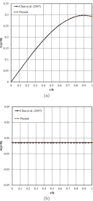
Example 1: To verify results of the present research for the rotating circular/annular plates, an isotropic solid circular plate previously analyzed by Chen et al. (2007) is reconsidered. Simultane-ous effects of the rotation and material heterogeneity will be investigated in the next examples. The elastic coefficients used by Chen et al. (2007), correspond to a general anisotropic case and cannot be used for the FGM plates. Similar to Chen et al. (2007), neither external loads nor edge conditions are imposed on the plate (the edge is free). The plate information is:
a=0, b=1m, h=0.1m, E=286
(
1+v)
(
1−2v)
1−v(
)
GPa, ρ=7600 kgm3, v=
Latin American Journal of Solids and Structures 10(2013) 859 – 890
The following dimensionless parameters are defined to extract the results:
Σi=
σi
ρω2b2 ,
U= uc11 0
ρω2b3 ,
W = wc11 0
ρω2b3 ( c
11 0
=286GPa)
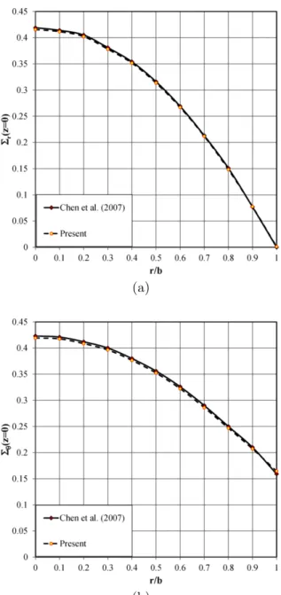
Variations of the displacement as well as the stress components of the bottom surface (z=0) are illustrated in Figures 3 and 4, respectively and compared with results of Chen et al. (2007). As it may readily be deduced, there is a good agreement between the results.
(a)
(b)
Latin American Journal of Solids and Structures 10(2013) 859 – 890
(a)
(b)
Figure 4 Radial variations of the in-plane stress components of the bottom surface of the rotating isotropic plate.
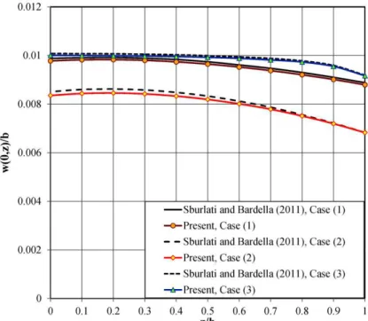
Example 2: To evaluate the accuracy of the present three-dimensional elasticity approach, an example is adopted from a work by Sburlati and Bardella (2011). Sburlati and Bardella (2011) proposed an analytical solution for stationary solid transversely-graded clamped circular plates under certain transverse pressures. In this regard, the following data are used:
a=0, b=45mm, h=15mm, E
0≡E
( )
0,0 =45 MPa, Eh≡E(
0,h)
=4500 MPa , m1=−2k1h=4.605,n
Latin American Journal of Solids and Structures 10(2013) 859 – 890
where ϕ1=z
1 0
/b and z
1 0
is the first positive root of J0(x), the zero-order Bessel function and is
equal to 2.404826. The imposed transverse pressure may be expressed with a good accuracy as:
P r
( )
=1− ϕ1r
( )
24 +
ϕ1r
( )
464 −
ϕ1r
( )
62304 +
ϕ1r
( )
8147456
MPa
Three sets of the Poisson ratio are considered:
(1) v=0.3
(2) v=0.499
(3) v
0≡v
(
0,0)
=0.499 , vh≡v(
0,h)
=0.01 (m3=−2kvh=−3.91 , n3 =0 )wherek 1=
1 2h
ln E0 E
h ⎛ ⎝⎜
⎞
⎠⎟≅ −0.1535 mm
−1 , k
v=
1 2h
ln v0 v
h ⎛ ⎝⎜
⎞
⎠⎟≅0.1303 mm
−1
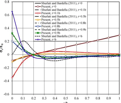
In Sburlati and Bardella (2011) paper, the coordinate z is measured from the top surface of the plate and is downward positive. Various combinations of the stress distributions are determined and compared with those of Sburlati and Bardella (2011) paper. In the first stage, the through-the-thickness distributions of the radial and transverse shear stresses of various radial sections are plotted in Figures 5 and 6, respectively for case (1). As Figure 5 shows, due to the bending-extension coupling caused by the non-homogeneous material properties and Poisson’s effect caused by the transverse loads, the upper layer of the plate tends to expand. For this reason, the radial stresses of this layer are negative in the neighborhood of the center section of the plate whereas they are positive in the neighborhood of the edge of the plate. This fact justifies the
dis-crepancy appeared in the through-the-thickness distribution of the radial stress at r=b. On the
other hand, since the neutral surface shifts toward regions with higher elasticity moduli, the max-imum transverse shear occurs in the neighborhood of this layer. For this reason, the maxmax-imum values of the transverse shear stress have occurred at a fixed location above the mid-surface of
the plate (at z h/ ≅0.2). This fact is independent of the location of the section or the transverse
loading pattern (as in the homogeneous plates or beams). Based on these facts, it seems that pre-sent results are slightly more accurate than those of Sburlati and Bardella (2011) paper.
Latin American Journal of Solids and Structures 10(2013) 859 – 890 Figure 5 A comparison among the through-the-thickness radial stress distributions, at various radial sections.
Latin American Journal of Solids and Structures 10(2013) 859 – 890
Figure 7 A comparison among the-through-the thickness distributions of the transverse displacement component of the center section of the plate, for various Poisson’s ratio distributions.
Figure 8 A comparison among the-through-the thickness distributions of the radial stress of the center section of the plate, for various Poisson’s ratio distributions.
Latin American Journal of Solids and Structures 10(2013) 859 – 890 Example 3: As a starting point for presenting new results, deformation patterns of a clamped-clamped two-directional functionally graded annular plate with the following information are studied:
a=100mm, b=500mm, h=50mm, E
0=286GPa, v=0.25, m1=0.5 , n1 =1
Results are plotted for P r
( )
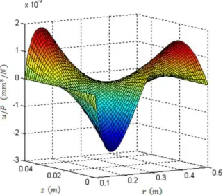
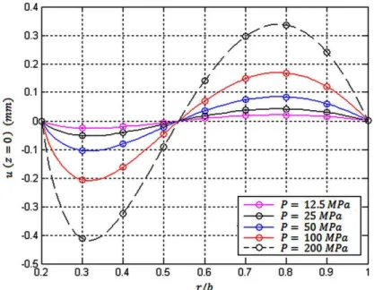
=12.5, 25, 50, 100, 200 MPa, for a better visualization in Figures 9to 15. Figures 9 and 10 present plots for the dimensionless in-plane (u/P) and transverse (w/P) displacement components, respectively. Based on the chosen geometric parameters, the plate is relatively thick and thus, effects of both the transverse pressure and the edge moments are equal-ly significant. As Figures 9, 11, and 12 show, signs of the in-plane displacement components of the upper and lower layers are opposite and their magnitudes are not similar (as Figures 13 and 14 confirm). On the other hand, due to the material heterogeneity (and consequently, variations
of location of the neutral surface in the interval 0.5<z/h<0.6 as one proceeds in the radial
direc-tion), there is a bending-extension coupling. It is known that the resulting stresses and displace-ments due to edge bending are identical to that of a thick cylinder subjected to external and in-ternal pressures [35]. Although the material properties vary exponentially in the transverse direc-tion, since the stress distribution is a result of an equilibrium rather than a kinematic require-ment, the trough-the-thickness distribution of the radial displacement component (as the radial stress component that is not shown) is somewhat linear and attains its maximum at layers whose moduli of elasticity are minimum.
Figure 16 shows effects of various edge conditions (CC, CS, SC, and SS) on the dimensionless lateral deflection of the bottom surface of the annular plate. As it may be expected, plates whose edges have more movability, experience greater deflections. So that, the maximum and minimum lateral deflections belong to the SS and CC edge conditions, respectively.
Latin American Journal of Solids and Structures 10(2013) 859 – 890
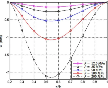
Figure 10 Three-dimensional representation of the simultaneous radial and through-the-thickness variations of the transverse displace-ment component of the clamped-clamped two-directional functionally graded annular plate.
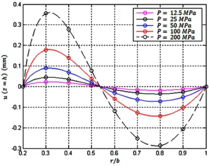
Latin American Journal of Solids and Structures 10(2013) 859 – 890 Figure 12 Radial variations of the in-plane displacement component of the upper surface of the clamped-clamped two-directional
func-tionally graded annular plate.
Latin American Journal of Solids and Structures 10(2013) 859 – 890
Figure 14 Through-the-thickness variations of the in-plane displacement component of the clamped-clamped two-directional functionally graded annular plate, at r=0.8b.
Latin American Journal of Solids and Structures 10(2013) 859 – 890 Figure 16 Influence of the edge conditions on the dimensionless lateral deflection of the bottom surface of the two-directional functionally
graded annular plate.
Example 4: A stress analysis is performed in the present example for a clamped-clamped two-directional functionally graded annular plate subjected to a uniformly distributed transverse load, resting on an elastic foundation. The following dimensionless parameters are defined to extract the results:
R= r
a, U=u
h,
W = w
h,
k*= k h
C
33
0 C33
0 = ⎡⎣1−ν
( )
r,z ⎤⎦E(r,z) 1−2ν( )
r,z⎡⎣ ⎤⎦⎡⎣1+ν
( )
r,z ⎤⎦⎛
⎝ ⎜ ⎜
⎞
⎠ ⎟ ⎟
Results are calculated based on the following data:
a=100mm¸ b=150mm, h=40mm, E=151GPa, υ=0.3, m
1=n1=1, P=1GPa, k *
=1
The through-the-thickness distributions of the dimensionless displacement components, the in-plane stress components, and the transverse normal and shear stresses of the mid-section of the plate (R=0.575) are depicted in Figures 17, 18, and 19, respectively.
Based on results illustrated in Figures 18 and 19, in the present example:
σ
Latin American Journal of Solids and Structures 10(2013) 859 – 890
while in the global plate theories (equivalent single layer theories; e.g., the third-order shear de-formation theory), it is assumed that
σθ ,σ
r τrz σz
In other words, results of the plate theories may be inaccurate for plates resting on elastic foun-dations. Furthermore, due to the same fact, in these cases, the transverse flexibility of the plate cannot be ignored, as it may be inferred from Figure 17. Moreover, order of the transverse dis-placement component is much higher than the in-plane one.
Figure 17 The through-the-thickness distributions of the displacement components of the mid-section of a transversely loaded two-directional functionally graded clamped annular plate resting on an elastic foundation.
A quick glance at Figure 18 reveals that the in-plane stress field may be considered to be a
result of a superposition of a hydrostatic pressure field (σθ =σ
r)and a bending stress field. Based
Latin American Journal of Solids and Structures 10(2013) 859 – 890 Figure 18 The through-the-thickness distributions of the in-plane stress components of the mid-section of a transversely loaded
two-directional functionally graded clamped annular plate resting on an elastic foundation.
Figure 19 The through-the-thickness distributions of the transverse stress components of the mid-section of a transversely loaded two-directional functionally graded clamped annular plate resting on an elastic foundation.
Example 5: Finally, a comprehensive sensitivity analysis is performed for a clamped-clamped functionally graded annular plate with the following information:
a=100mm, b=500mm, h=50mm, E
0=180GPa, v=0.3
Latin American Journal of Solids and Structures 10(2013) 859 – 890
(i) In the first stage, a stationary annular plate with P r
( )
=200MPa is analyzed for the followingdistinct cases:
Case � ∶ A radially−graded plate �! =0 with the following sub−cases:
(1) n
i =−2,
(2) n
i =−1,
(3) n
i =0,
(4) n
i =1,
(5) n
i =2,
Case � ∶ A radially−graded plate �!=0 with the following sub−cases:
(1) m
i =−2,
(2) m
i =−1,
(3) m
i =0,
(4) m
i =1,
(5) m
i =2.
where i takes the values 1 or 2.
(ii) A two-directional functionally graded (m
1=n1=1) annular plate with the following uniform
and non-uniform loads:
(1) P r
( )
=200MPa,(2) P r
( )
=1000 r−100 MPa,(3) P r
( )
=−1000 r+500 MPa.(iii) A two-directional functionally graded (m
1=n1=1) annular plate with a uniform � � =
200 ��� load and one of the following coefficients of the elastic foundation:
(1) k
1=0,
(2) k
1=0.001,
(3) k
1=0.01.
where :
k
1=kh/E0
(iv) A two-directional functionally graded (m
1=n1=1) annular plate with a uniform
P r
( )
=200 MPa load and one of the following angular speeds:(1) ω=0,
(2) ω=20000RPM.
Although variations of all the displacement and stress components may be plotted, only results that lead to more adequate conclusions are reported here to save space.
Latin American Journal of Solids and Structures 10(2013) 859 – 890
20 confirm that for a specified �!
value, bending/extensional rigidity of the cross sections
increas-es as higher �!
values are adopted. For this reason, the maximum lateral deflection has occurred
before the mid-section r/b=0.6 for negative �!
values and after that section for positive ni
val-ues. From Figure 21, it may be concluded that generally, although the through-the-thickness dis-tribution of the radial stress of the thick plate may not be a linear one, the deviations from the linear distribution are ignorable for the middle layers. It is evident that in addition to the bend-ing of the plate, the exerted transverse load causes the layers to expand, especially in layers that are adjacent to the top or bottom (when an elastic foundation exists) layer. Figure 22 reveals that
although the lateral deflection of the plate may decrease for greater m
i values, location of the
maximum lateral deflection is almost independent of m
i . As discussed in the foregoing example,
in this case, the dominant in-plane stress field is the hydrostatic one. For this reason, radial dis-tribution of the hoop stress of the mid-surface is investigated in Figure 23 to provide results di-versity.
Analysis (ii) has been adopted to show that location of the maximum lateral deflection is de-pendent on both the radial material index and the load distribution. Therefore, by choosing a proper material gradient, location of the maximum deflection can be shifted. For a uniform load distribution, location of the maximum lateral deflection occurrence is mainly affected by the radi-al materiradi-al index (Figure 24). However, non-uniform load distribution may affect this location. The relevant through-the-thickness distributions of the radial stress of the mid-section of the two-directionally graded annular plate are plotted in Figure (25).
In the previous examples, it has been proven that increasing the foundation stiffness reduces both the displacement components and the in-plane stress components. Figure (26) that illus-trates influence of the foundation stiffness on the dimensionless lateral deflection of the bottom surface of the two-directional functionally graded plate, confirms the first fact. However, as Fig-ure (27) demonstrates, the transverse normal stress component increases with the foundation stiffness.
Latin American Journal of Solids and Structures 10(2013) 859 – 890
Figure 20 Radial variations of the dimensionless lateral deflection of the bottom surface of the radially-graded clamped-clamped annular plate, for various material indices [Case (A) of analysis (i)].
Latin American Journal of Solids and Structures 10(2013) 859 – 890 Figure 22 Radial variations of the dimensionless lateral deflection of the bottom surface of the transversely-graded clamped-clamped
annular plate, for various material indices [Case (B) of analysis (i)].
Latin American Journal of Solids and Structures 10(2013) 859 – 890
Figure 24 Radial variations of the dimensionless lateral deflection of the bottom surface of the two-directionally graded clamped-clamped annular plate, for various load distributions of analysis (ii).
Latin American Journal of Solids and Structures 10(2013) 859 – 890 Figure 26 Influence of the foundation stiffness on the radial variations of the dimensionless lateral displacement of the bottom surface of
the two-directional functionally graded clamped annular plate.
Latin American Journal of Solids and Structures 10(2013) 859 – 890
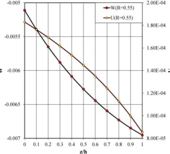
Figure 28 Effect of the angular speed on the dimensionless radial displacement component of the top surface of the transversely loaded two-directional functionally graded annular plate: (1) stationary plate, (2) rotating plate [analysis (iv)].
Latin American Journal of Solids and Structures 10(2013) 859 – 890 5 C O N C LU SIO N S
In the present paper, a Hermitian finite element bending and stress analysis is presented for two-directional functionally graded circular/annular plates and disks for the first time, employing the three-dimensional theory of elasticity.
Some of the innovations incorporated in the present research are:
- Comprehensive analysis of the two-directional functionally graded annular and circular
plates.
- Using the three-dimensional theory of elasticity, for various combinations of the loading
and edge conditions. Mixed (Dirichlet-type and Neumann-type) boundary conditions may be applied based on the presented solution algorithm.
- Effects of the angular speed are considered in conjunction with the material heterogeneity.
Therefore, the resulted bending-extensional coupling is implicitly taken into account.
- The plate may be supported by a non-uniform elastic foundation.
- The proposed formulation and the presented results are comprehensive and cover many
practical applications.
- In contrast to the very limited works presented for the rotating functionally graded
circu-lar plates so far, the through-the-thickness stress distribution and bending of the loaded plates are investigated. Furthermore, the loads may vary in an arbitrary pattern in the radial direction.
- Some of the practical annular/circular plates considered in the results section are:
a) Stationary annular/circular plates.
b) Radially-graded, transversely-graded, and two-directional graded heterogeneous
annu-lar and circuannu-lar plates and disks.
c) Plates resting on soft or rigid substrates and plates without elastic foundations.
d) Rotating plates with the specifications mentioned in items (b) and (c).
Results reveal that choosing a proper material distribution may lead to a more suitable stress distribution, enhance the sections rigidity or shift the critical points with respect to the displace-ment components. On the other hand, the angular speed may alter the nature of the stresses of the transversely loaded annular plate or disk.
References
Alipour, M.M., Shariyat, M., Shaban, M., (2010). A semi-analytical solution for free vibration of variable thickness two-directional-functionally graded plates on elastic foundations. Interna-tional Journal of Mechanics and Materials in Design 6(4): 293-304.
Alipour, M.M., Shariyat, M., (2011). Semi-analytical buckling analysis of heterogeneous variable thickness viscoelastic circular plates on elastic foundations. Mechanics Research Communica-tions 38: 594-601.
Latin American Journal of Solids and Structures 10(2013) 859 – 890
Bayat, M., Sahari, B.B., Saleem, M., Ali, A., Wong, S.V., (2009b). Thermoelastic solution of a functionally graded variable thickness rotating disk with bending based on the first-order shear deformation theory. Thin-Walled Structures 47: 568–582.
Chen, J.-Y., Chen, W.-Q., (2007). 3D analytical solution for a rotating transversely isotropic annular plate of functionally graded materials. Journal of Zhejiang University Science A 8(7): 1038-1043.
Chen, J.-Y., Ding, H.-J., Chen, W.-Q., (2007). Three-dimensional analytical solution for a rotat-ing disc of functionally graded materials with transverse isotropy. Archive of Applied Mechan-ics 77: 241–251.
Garcia, O.A., Proença, S.P.B., (2007). Linear analysis of axis-symmetric plates and shells by the generalized Finite Element Method. Latin American Journal of Solids and Structures 4: 121-147.
Golmakani, M.E., Kadkhodayan, M., (2011). Nonlinear bending analysis of annular FGM plates using higher-order shear deformation plate theories. Composite Structures 93: 973–982.
Hosseini Kordkheili, S.A., Naghdabadi, R., (2007). Thermoelastic analysis of a functionally graded rotating disk. Composite Structures 79: 508–516.
Kim, W., Reddy, J.N., (2010). Novel mixed finite element models for nonlinear analysis of plates. Latin American Journal of Solids and Structures 7: 201–226.
Lei, Z., Zheng, Z., (2009). Exact solution for axisymmetric bending of functionally graded circular plate. Tsinghua Science and Technology 14: 64-68.
Li, X.Y., Ding, H.J., Chen, W.Q., (2008a). Elasticity solutions for a transversely isotropic
func-tionally graded circular plate subject to an axisymmetric transverse load qrk. International
Journal of Solids and Structures 45: 191–210.
Li, X.Y., Ding, H.J., Chen, W.Q., (2008b). Three-dimensional analytical solution for functionally graded magneto–electro-elastic circular plates subjected to uniform load. Composite Structures 83: 381–390.
Ma, L.S., Wang, T.J., (2004). Relationships between axisymmetric bending and buckling solu-tions of FGM circular plates based on third-order plate theory and classical plate theory. In-ternational Journal of Solids and Structures 41: 85–101.
Nie, G., Zhong, Z., (2007).Axisymmetric bending of two-directional functionally graded circular and annular plates. Acta Mechanica Solida Sinica 20: 289-295.
Nie, G.J., Zhong, Z., (2010). Dynamic analysis of multi-directional functionally graded annular plates. Applied Mathematical Modeling 34(3): 608–616.
Peng, X.-L., Li, X.-F., (2010). Thermal stress in rotating functionally graded hollow circular disks. Composite Structures 92: 1896–1904.
Polat, C., (2010). An assessment of a co-rotational EAS brick element. Latin American Journal of Solids and Structures 7: 77–89.
Reddy, J.N., (2006). An introduction to the finite element method. 2nd Edition, New York: Wiley.
Latin American Journal of Solids and Structures 10(2013) 859 – 890
Shariyat, M., (2009a). A nonlinear Hermitian transfinite element method for transient behavior analysis of hollow functionally graded cylinders with temperature-dependent materials under thermo-mechanical loads. International Journal of Pressure Vessels and Piping 86: 280-289. Shariyat, M., (2009b). A rapidly convergent nonlinear transfinite element procedure for transient
thermoelastic analysis of temperature-dependent functionally graded cylinders. Journal of Solid Mechanics 1(4): 313-327.
Shariyat, M., (2010a). Non-linear dynamic thermo-mechanical buckling analysis of the imperfect sandwich plates based on a generalized three-dimensional high-order global-local plate theory. Composite Structures 92: 72-85.
Shariyat, M., (2010b). A generalized high-order global-local plate theory for nonlinear bending and buckling analyses of imperfect sandwich plates subjected to thermo-mechanical loads. Composite Structures 92: 130-143.
Shariyat, M., (2011a). A nonlinear double-superposition global-local theory for dynamic buckling of imperfect viscoelastic composite/sandwich plates: a hierarchical constitutive model. Compo-site Structures 93: 1890-1899.
Shariyat, M., (2011b). An accurate double superposition global-local theory for vibration and bending analyses of cylindrical composite and sandwich shells subjected to thermomechanical loads. Proceedings of the Institution of Mechanical Engineers, Part C: Journal of Mechanical Engineering Science 225: 1816-1832.
Shariyat, M., (2011c). Nonlinear thermomechanical dynamic buckling analysis of imperfect viscoe-lastic composite/sandwich shells by a double-superposition global-local theory and various con-stitutive models. Composite Structures 93: 2833-2843.
Shariyat, M., (2012). A general nonlinear global-local theory for bending and buckling analyses of imperfect cylindrical laminated and sandwich shells under thermomechanical loads. Meccanica 47; 301-319.
Shariyat, M., Alipour, M.M., (2011). Differential transform vibration and modal stress analyses of circular plates made of two-directional functionally graded materials resting on elastic founda-tions. Archive of Applied Mechanics 81: 1289-1306.
Shariyat, M., Eslami, M.R., (1996). Isoparametric finite-element thermoelastoplastic creep analy-sis of shells of revolution. International Journal of Pressure Vessels and Piping 68(3): 249-259. Shariyat, M., Khaghani, M., Lavasani, S.M.H., (2010). Nonlinear thermoelasticity, vibration, and
stress wave propagation analyses of thick FGM cylinders with temperature-dependent material properties. European Journal of Mechanics A/Solids, 29: 378-391.
Shariyat, M., Lavasani, S.M.H., Khaghani, M., (2010b). Nonlinear transient thermal stress and elastic wave propagation analyses of thick temperature-dependent FGM cylinders, using a se-cond-order point-collocation method. Applied Mathematical Modelling 34: 898-918.
Shariyat, M., Nikkhah, M., Kazemi, R., (2011). Exact and numerical elastodynamic solutions for thick-walled functionally graded cylinders subjected to pressure shocks. International Journal of Pressure Vessels and Piping 88: 75-87.
Latin American Journal of Solids and Structures 10(2013) 859 – 890
Wang, Y., Xu, R.Q., Ding, H.J., (2010). Three-dimensional solution of axisymmetric bending of functionally graded circular plates. Composite Structures 92: 1683–1693.
Yang, B., Ding, H.J., Chen, W.Q., (2008). Elasticity solutions for a uniformly loaded annular plate of functionally graded materials. Structural Engineering Mechanics 30(4): 501–12.
Zienkiewicz, O.C., Taylor, R.L., (2005). The Finite Element Method: Its Basis and Fundamentals.