Performance assessment of flat slabs strengthened with a bonded
reinforced concrete overlay
Massimo Lapi1, Hugo Fernandes2, Maurizio Orlando3, António Ramos4, Válter Lúcio5
1 PhD Student, Department of Civil and Environmental Engineering, University of Florence, Florence, Italy
2 PhD Student, Department of Civil Engineering, Faculdade de Ciências e Tecnologia, Universidade NOVA de Lisboa, Caparica, Portugal
3 Associate Professor, Department of Civil and Environmental Engineering, University of Florence, Florence, Italy
4 Assistant Professor, CERIS, ICIST, Department of Civil Engineering, Faculdade de Ciências e Tecnologia, Universidade NOVA de Lisboa, Caparica, Portugal
5 Associate Professor, CERIS, ICIST, Department of Civil Engineering, Faculdade de Ciências e Tecnologia, Universidade NOVA de Lisboa, Caparica, Portugal
ABSTRACT
Punching strengthening of R/C slabs using a Bonded Reinforced Concrete Overlay (BRCO) is an efficient alternative to traditional strengthening systems such as post-installed shear reinforcement, enlargement of the support column, or bonded FRP strips. The BRCO technique allows for both flexural stiffness and shear strength of existing slabs to be increased. Shear strength increases due to the greater slab thickness, while the increase in flexural stiffness is also provided by the added reinforcement. A special attention regarding the interface between the existing slab and the BRCO is required, since performance gains can only be achieved if the existing slab and the new concrete layer work monolithically. Interface performance can be improved through surface preparation and mechanical connectors, the latter is recommended to avoid a premature debonding failure. This paper presents an ad-hoc design approach for flat-slabs strengthened with BRCO based on the Critical Shear Crack Theory (CSCT), which accounts for the slab rotation after strengthening. This is a fundamental
parameter to assess the punching capacity of the strengthened slab. The efficiency of the proposed method is confirmed by the agreement between analytical results and experimental data collected during an experimental campaign carried out at the Universidade NOVA de Lisboa.
Keywords:
Punching, Slabs & plates, Structural analysis. Notation:
𝐸𝑐 modulus of elasticity of the concrete
𝐸𝑠 modulus of elasticity of longitudinal reinforcement
𝐿 span of the slab
𝑉 shear load applied to the slab 𝑉𝑒𝑥𝑝 experimental failure load 𝑉𝑅 punching shear strength
𝑉𝑅,𝑎𝑠 predicted failure load after strengthening
𝑉𝑅,𝑏𝑠 predicted failure load before strengthening
𝑉𝑅,𝑐𝑟𝑢𝑠ℎ punching shear strength governed by crushing of concrete strut 𝑉𝑠𝑡 load level at strengthening
𝑎𝑠 cross-sectional area of existing longitudinal reinforcement per unit width
𝑎𝑠,𝑠𝑡 cross-sectional area of BRCO longitudinal reinforcement per unit width 𝑏0 length of control perimeter set at 𝑑/2 from the column
𝑏0,𝑠𝑡 length of control perimeter set at 𝑑𝑠𝑡/2 from the column
𝑐 compressive depth of un-strengthened section
𝑐′ compressive depth of strengthened section before yielding of existing reinforcement
𝑐′′ compressive depth of strengthened section after yielding of existing reinforcement
𝑑 effective depth of the existing longitudinal reinforcement 𝑑𝑠𝑡 effective depth of the BRCO longitudinal reinforcement
𝑑𝑔 maximum aggregate size of existing slab 𝑑𝑔,𝑠𝑡 maximum aggregate size of BRCO
𝑑𝑔0 reference size of aggregate equal to 16 mm
𝑓𝑐 average concrete compression strength of existing slab fc,cube average compression strength of concrete cubes 𝑓𝑐,𝑒𝑞 equivalent concrete compression strength of strengthened slab
𝑓𝑐,𝑠𝑡 average concrete compression strength of BRCO 𝑓𝑐𝑡 average concrete tensile strength of existing slab
𝑓𝑐𝑡,𝑠𝑡 average concrete tensile strength of BRCO
𝑓𝑦 yield strength of existing steel reinforcement 𝑓𝑦,𝑠𝑡 yield strength of BRCO steel reinforcement
ℎ existing slab depth
ℎ𝑠𝑡 total depth of slab after strengthening (existing slab + BRCO) 𝑚 bending moment per unit width
𝑚𝑐𝑟 cracking moment per unit width of existing unstrengthened slab
𝑚𝑐𝑟′ cracking moment per unit width of strengthened slab
𝑚𝑟 radial moment per unit width 𝑚𝑡 tangential moment per unit width
𝑚𝑅 ultimate moment per unit width of unstrengthened slab
𝑚𝑅′ ultimate moment per unit width of strengthened slab
𝑚𝑠𝑡 design moment per unit width acting at strengthening time 𝑟 radial distance
𝑟0 radius of the critical shear crack
𝑟𝑞 radial distance of the load from the column axis 𝑟𝑠 radius of the circular isolated slab
𝑟𝑠𝑡 radius of strengthened area
𝑤 crack width
𝛽 efficiency factor of the stiffness in cracked phase, accounting for the orthogonal layout of the reinforcement
𝜌 longitudinal reinforcement ratio of existing slab (𝑎𝑠/𝑑)
𝜌𝑠𝑡 longitudinal reinforcement ratio of BRCO (𝑎𝑠,𝑠𝑡/𝑑𝑠𝑡)
𝜒 curvature of a section
𝜒1 curvature in stabilized cracking of unstrengthened section
𝜒1′ curvature in stabilized cracking of strengthened section
𝜒𝑐𝑟 curvature at cracking of unstrengthened section 𝜒𝑐𝑟′ curvature at cracking of strengthened section
𝜒𝑟 radial curvature
𝜒𝑠𝑡 curvature at strengthening
𝜒𝑇𝑆 decrease in curvature due to tension stiffening
𝜒𝑡 tangential curvature
𝜒𝑦 curvature corresponding to 𝑚𝑅 of unstrengthened section 𝜒𝑦′ curvature corresponding to 𝑚𝑅′ of strengthened section
𝜒𝑦,𝑢 curvature corresponding to the yielding of existing reinforcement
𝜓 slab rotation
𝜓𝑅 slab rotation at failure
1 Introduction
The issue of punching in concrete structures, namely flat slabs, has been the subject of several studies in the field of Civil Engineering research. Many of these studies were developed after structural collapses caused by punching, also in recent times. Moreover, many researches were motivated by the need for developing new mechanical models able to overcome the empirical formulations proposed by design codes like the Eurocode 2 (CEN, 2004) and ACI 318-14 (ACI, 2014). Punching is a brittle failure mode that can cause the progressive collapse of the whole structure, especially if the design of the original slab did not comprise any integrity reinforcement crossing the column.
The growing number of existing buildings that require structural intervention lead to the development of new strengthening techniques (Foraboschi, 2016) and mechanical models according to recent design codes e.g. SIA 262 (SIA, 2003) and Model Code 2010 (fib, 2013). Specifically, flat slabs often require strengthening due to design or durability issues, to increase the load-bearing capacity due to change of use, or to improve the seismic behaviour of the structure.
Several studies were carried out since the early twentieth century to investigate the punching failure mechanism, with a great number based on empirical approaches and others on mechanical models. In the early 1960’s, Kinnunen and Nylander (1960) developed a mechanical theory based on the assumption that punching shear strength is reached for a given critical rotation, with this being the benchmark mechanical model for many subsequent theories. In 1989, following Kinnunen and Nylander mechanical approach, Shehata and Regan (1989) proposed a new model where they hypothesized three different types of failure. Later, Broms (1990) introduced a modified approach of the Kinnunen and Nylander (1960) method, including unsymmetrical punching and size effect. Starting from 1991, and also following the latter method, Muttoni and Schwartz (1991) began developing a new mechanical model, with the first draft of this model published in 2003 (Muttoni, 2003). In 2008 the final version of the Critical Shear Crack Theory (CSCT) was published (Muttoni, 2008). The substantial difference regarding previous models lies in the choice of the CSCT failure
criterion, which was inspired by the previous works of Walraven (1981), and Vecchio and Collins (1986). They stated that a rough crack can transfer shear by aggregate interlock, which is a function of crack width, compressive strength and aggregate size. Therefore, CSCT describes the relationship between punching strength and the width of the critical shear crack, accounting for its roughness. The critical state is set at the intersection between two curves: the first describing the failure criterion, accounting for the aforementioned parameters, and the second representing the load-rotation relationship of the flat slab (Figure 1).
Figure 1 - Calculation of the punching capacity for slabs without shear reinforcement according to the CSCT, adapted from Muttoni A (2008)
Most design approaches based on empirical formulas do not acknowledge the influence of the load level at time of strengthening, while the CSCT can account for this parameter. This particular characteristic was preponderant for the utilization of the CSCT to evaluate the punching shear capacity of existing slabs strengthened with BRCO, after introducing some modifications to make the CSCT suitable to this particular case. The CSCT versatility allows for it to be applied in many different cases, like flat slabs with asymmetric reinforcement (Sagaseta et al., 2011), shear reinforcement (Ruiz et al., 2009; Lips, 2012), steel fibre reinforced concrete (Maya et al., 2012; Gouveia et al, 2014), and
prestressed concrete slabs (Climent et al., 2013 and 2014). It can also be applied to strengthening techniques like the use of externally glued fibre reinforced polymers (Faria et al., 2014) or post-installed shear reinforcement (Ruiz et al.,2010; Silva et al., 2013; Inácio et al., 2012). Its broad applicability allowed CSCT to be included in codes of practice, being also the basis for the Model Code 2010 punching design and verification.
A specific strengthening technique with a Bonded Reinforced Concrete Overlay (BRCO) on the upper face of the support column regions of flat slabs is presented in this work (Figure 2).
Figure 2 – The Bonded Reinforced Concrete Overlay (BRCO)
The aim of this paper is to propose an ad hoc design approach based on the CSCT. The authors have followed a similar method to that used by Faria et al. (2014) for slabs strengthened with FRP strips on the upper face, but defined a new failure criterion and a new load-rotation curve (Figure 4). Finally, the proposed method was validated by comparison with results of an experimental campaign carried out at the Department of Civil Engineering, Universidade NOVA de Lisboa (Fernandes et al., 2016). The proposed design approach assumes that the substrate and the BRCO behave monolithically, as the premature debonding of the overlaid concrete is prevented by shear connectors. The efficacy of the method to predict experimental results is evaluated on a reduced number of tests; its general validity could be assessed only after extending the experimental campaign to other specimens, varying the thickness of the overlay, the reinforcement ratio, or other key parameters.
2 BRCO technique
The BRCO technique consists in casting a concrete layer on the upper face of existing slabs in the regions of support columns (Figure 2), after preparing the contact surface. This is fundamental to achieve an almost monolithic behaviour of the resulting composite cross-section. Concrete quality, cleanliness and roughness of the top surface of the existing slab (substrate) are also important to enhance bonding of the two different concrete layers. The interface is usually roughened by high-pressure water-jetting, milling, shot-blasting, sand-blasting, among other techniques (Julio et al., 2004). The use of mechanical connectors as stitching reinforcement is fundamental to ensure an adequate interface bond performance and shear strength (Rocha, 2012). Figure 3 shows the three ways stitching reinforcement can be detailed in a column region: making use of punching shear reinforcement, installing dowels as shear connectors, or anchoring longitudinal reinforcement of the new layer at its ends.
Figure 3 – (a) Longitudinal and punching shear reinforcement; (b) shear connectors crossing the interface; (c) anchorage of the bundled longitudinal reinforcement (Rocha DW, 2012)
In those cases where enough clear cover is available, the new concrete layer could be embedded in the existing slab, otherwise it can be casted above the slab. In the latter case, the formation of a step in the floor can be avoided by casting the overlay outside the strengthened area, where the self-weight of the new layer can be reduced by using lightweight concrete. Alternatively, the step can be eliminated by adopting different depths of the floor screed.
Effects of BRCO strengthening are visible in the modification of both the load-rotation curve and the failure criterion (Figure 4). The load-rotation curve becomes stiffer and the failure criterion is shifted upwards due to the increase of the effective depth. Consequently, the punching shear capacity of the slab also increases after BRCO strengthening (𝑉𝑢,𝑎𝑠), with usually the flexural capacity (𝑉𝑓𝑙𝑒𝑥) also increasing. As depicted in Figure 4, the dashed line represents the behaviour before strengthening. Applying the BRCO on the tensile face of the slab leads to an increase of stiffness and flexural capacity, and thus the new load-rotation relationship intercepts the resulting failure criterion higher than before strengthening (𝑉𝑢,𝑏𝑠). This leads to an increase of the slab’s punching shear capacity.
Figure 4 - Load-rotation curve and failure criterion
The resulting cross-section formed by the two concrete layers should work as a monolithic section, with the requirement for the performance of the BRCO technique that it does not debond from the existing slab, being the failure mode associated to debonding not dealt with in the method proposed in this work.
The load-rotation curve shown in Figure 4 holds if the slab is loaded until A and then is strengthened, but in practice the slab is usually loaded to a certain load and then it is unloaded at the time of strengthening. The effect of this unloading and reloading of the existing slab (URL) has been studied, among others, by Koppitz (2015), and it consists of an increase in the slab rotation (Δψurl) (Figure 5).
Since the punching strength decreases with increasing rotation, additional deformations caused by the load history may also be important for the evaluation of the strengthening technique.
Figure 5 – Effect of URL path, adapted from (Koppitz R, 2015)
However, the studies and experimental campaign performed by Koppitz (2015) have shown that the effect of URL cycles is limited, as the punching strength decreases only 1 5%. Furthermore, as the BRCO strengthening increases the slab stiffness, it can be assumed that the reloading path is steeper and Δψurl is reduced with respect to the unreinforced slab. Due to the reduced impact of the URL cycles
on the behaviour and punching shear capacity of the composite cross-section, the resulting residual rotation will be neglected in this work.
3 Mechanical behaviour of flat slabs strengthened with BRCO
Failure Criterion of concrete
According to the CSCT, the punching shear strength of flat slabs without shear reinforcement depends on several factors, such as the amplitude of the critical shear crack (𝑤), given by the product of rotation (𝜓) and effective depth of the slab (𝑑), the roughness of the critical crack, that depends on the maximum aggregate size (𝑑𝑔), concrete strength (𝑓𝑐) and the size of the critical surface, given by the
product of effective depth (𝑑) and control perimeter (𝑏0), set at 0.5 𝑑 from the column. The resulting failure criterion is then:
𝑉𝑅 𝑏0⋅𝑑⋅√𝑓𝑐= 3 4 ⁄ 1+15⋅𝜓⋅𝑑 𝑑𝑔0+𝑑𝑔 (1)
Zohrevand et al. (2014) observed that using a higher strength concrete up to half the depth of the tension face of a flat slab did not increase the punching capacity significantly. Also, and since it’s good practice to use higher strength concrete on the overlay, considering only the concrete strength of the substratum in the calculations is a conservative approach for Equation (1). According to Muttoni (2008) the amount of shear that can be transferred across the critical shear crack depends on the roughness of the crack, which in its turn is a function of the maximum aggregate size. Since the critical shear crack must cross the full cross-section of the slab, eventual differences between the maximum aggregate size of both concretes used in the substrate and the BRCO should be accounted for. Walraven (1981) and Vecchio and Collins (1986) state that the friction mechanism is correlated with strength and size of aggregates on the critical surface. Since the critical shear crack crosses both concrete layers, friction is affected by characteristics of each layer. Therefore, the maximum aggregate size to be used in Equation (1) may be weighted by the thickness of each layer, as shown in Equation (2):
𝑑𝑔,𝑒𝑞 =ℎ⋅𝑑𝑔+(ℎℎ𝑠𝑡−ℎ)⋅𝑑𝑔,𝑠𝑡
𝑠𝑡 (2)
Under this assumption, results are in good agreement with experimental data (see section 5.2), even for specimens where initially both layers are uncracked and friction in the existing slab weights more than in BCRO. Nevertheless, further research is needed to refine equation (2) by introducing ad-hoc weighting coefficients to account for different values of crack width in the two layers. The maximum crack width and critical surface are calculated using the effective depth of the BRCO longitudinal reinforcement (𝑑𝑠𝑡), which holds if the substrate is not cracked at strengthening time. If the substrate
is already cracked, this hypothesis does not describe the actual crack profile, but it can be considered as it overestimates the crack width in the BRCO with results on the safe side. Furthermore,
characterization of the entire critical surface requires the calculation of its size using the overlay effective depth:
𝑤 = 𝜓 ⋅ 𝑑𝑠𝑡 (4)
𝐴𝑐𝑟 = 𝑏0,𝑠𝑡⋅ 𝑑𝑠𝑡 (5)
The failure criterion then becomes:
𝑉𝑅 𝑏0,𝑠𝑡⋅𝑑𝑠𝑡⋅√𝑓𝑐= 3 4 ⁄ 1+ 15⋅𝜓⋅𝑑𝑠𝑡 𝑑𝑔0+𝑑𝑔,𝑒𝑞 (6)
At the time of strengthening the existing slab is usually cracked, with maximum crack (𝑤) width equal to 𝜓 ⋅ 𝑑, while the BRCO is uncracked. As the structure is reloaded, the BRCO cracks and the corresponding crack width at the top surface is proportional to the rotation increase after strengthening (∆𝜓 = 𝜓 − 𝜓𝑠𝑡), and not to the total rotation (𝜓). Accounting for the rotation of the existing slab under service loads at the time of strengthening (𝜓𝑠𝑡), the maximum crack width at the top slab´s surface is
given by (𝜓 − 𝜓𝑠𝑡) ⋅ 𝑑𝑠𝑡.
Nevertheless, to make the proposed approach easier to implement, the authors assume that the strengthened slab crack width is proportional to the existing slab rotation (𝜓).
Load – rotation relationship
The load-rotation curve, besides the failure criterion, are the fundamental elements of the CSCT analysis for the punching shear strength evaluation. According to this theory, the load-rotation curve (𝑉, 𝜓) is built starting from the slab rotation (𝜓) according to the following steps:
a. Fixing of a rotation value (𝜓);
b. Calculation of the tangential curvature distribution (𝜒𝑡); c. Writing of the quadrilinear relationship (𝑚, 𝜒);
d. Determination of the tangential moment distribution (𝑚𝑡);
f. Calculation of the shear load (𝑉).
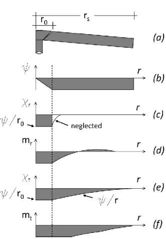
Figure 6 – Assumed behaviour for axisymmetric slab: (a) conical shape; (b) rotation of the slab; (c) distribution of radial curvature; (d) distribution of radial moments; (e) distribution of tangential curvature; (f) distribution of tangential moments
for quadrilinear moment-curvature relationship (adapted from Muttoni, 2008)
Some modifications are required to allow the application of the CSCT to BRCO strengthened slabs. The main focus is the construction of the quadrilinear moment-curvature relationship (𝑚, 𝜒) as it depends on the strengthening characteristics and degree of loading of the existing structure, as depicted in Figure 7. In addition to the initial slab configuration before strengthening (a), depending on the time the BRCO is placed, three cases may be distinguished:
- strengthening during the elastic phase of the section (b); - strengthening during the cracked phase of the section (c); - strengthening at the yielding plateau (d).
- Figure 7 – Moment-curvature relationships: (a) un-strengthened slab; (b) strengthening during the elastic phase; (c) strengthening during the cracked phase; (d) strengthening at the yielding plateau
Each case is characterized by a different moment-curvature relationship, depending on the stage of loading at the time of strengthening. For each curve in Figure 7, the fundamental parameters to consider are the uncracked stiffness, the critical moment that characterizes the change to the cracked phase, cross-section cracked stiffness (before and/or after yielding of existing reinforcement), and ultimate flexural moment. This approach was also used by Faria et al. in (2014), concerning the strengthening of flat slabs with FRP strips. Appendix A and B provide all the elements required for the determination of the listed parameters.
4 Parameters influencing the punching capacity of strengthened slabs
The BRCO technique allows increasing the punching strength, with its efficiency varying with the load level at strengthening. A parametric study was performed to investigate the influence on the punching capacity. The parameters considered were the new layer’s reinforcement ratio and thickness, and the load level at strengthening.
Influence of the reinforcement ratio
To assess the impact of reinforcement ratio on strengthened slabs, four ratios were considered for 220 mm slab substrates: ρ = 0.5 %, 1.0 %, 1.5 %, 2.0 %. Along with the different reinforcement ratios of the existing slabs, the longitudinal reinforcement diameter of the new layer was also varied (∅ = 12 mm, 14 mm, 16 mm , and 18 mm), with a fixed spacing of 150 mm. The strengthening is assumed performed at a shear load equal to 50 % of the predicted punching shear load capacity before strengthening (𝑉𝑠𝑡 = 0.5 𝑉𝑅,𝑏𝑠). At this stage, BRCO thickness was 50 mm. The concrete compressive
strength was 30 MPa for both layers, the yield strength of all reinforcement was 450 MPa, and maximum aggregate size was 16 mm. Finally, the columns were assumed 400 x 400 mm, arranged in a square grid of 8 x 8 m.
(𝑐) (𝑑) Figure 8 – Influence of the BRCO’s reinforcement ratio
Figure 8 shows that BRCO strengthening is more effective on slabs with low reinforcement ratios, and less on slabs with a larger reinforcement ratio. The same considerations can be drawn regarding the influence of BRCO longitudinal reinforcement presented in Table 1.
Table 1 – Punching shear strength of existing and strengthened slabs with different reinforcement ratios and BRCO’s longitudinal reinforcement diameters (h=220 mm, h0=50 mm, fc= 30 MPa, dg=16 mm)
Influence of the load level at strengthening
In Figure 9, analysis of the influence of load level at strengthening of a 220 mm thick slab with a reinforcement ratio of 1.5 %, strengthened with a 50 mm RC layer and 12mm bars spaced 150 mm. Two load levels were considered at the time of strengthening, 𝑉𝑠𝑡= 0 and 𝑉𝑠𝑡= 500 𝑘𝑁. When the
Longitudinal reinforcement ratio of existing slab ρ = 0,5% ρ = 1,0% ρ = 1,5% ρ = 2,0% VR [kN] Existing slab 475 685 800 855 Strengthened slab with BRCO ∅12 770 (+62%) 920 (+34%) 995 (+24%) 1060 (+24%) ∅14 815 (+72%) 945 (+38%) 1020 (+28%) 1075 (+26%) ∅16 855 (+80%) 975 (+42%) 1040 (+30%) 1090 (+27%) ∅18 890 (+87%) 995 (+45%) 1060 (+33%) 1115 (+30%)
strengthening was performed with the slab loaded (𝑉𝑠𝑡 = 500 𝑘𝑁) the predicted punching capacity was lower, but for slabs with medium amount of longitudinal reinforcement (𝜌 = 1 − 1.5%), the load level at strengthening has a small effect on the load capacity of the strengthened slab, as shown in Figure 9 and Table 2 (in this particular case a reduction of about 7%).
Figure 9 – Influence of the strengthening load level
VR [kN]
Existing slab 800
Strengthened slab with BRCO at:
0 kN 1050 (+31%)
500 kN 980 (+23%)
Table 2 – Punching shear strength of existing and strengthened slabs at different load levels
Impact of the BRCO thickness
The influence of the BRCO thickness was studied on the aforementioned existing slab, and analysed for two values of 50 𝑚𝑚 and 80 𝑚𝑚, with both scenarios depicted in Figure 10 for the load-rotation relationship and failure criterion. The influence of changing the BRCO thickness on the punching
capacity from 50 𝑚𝑚 to 80 𝑚𝑚 was also relatively low, increasing about 6 % over the smaller thickness BRCO. Results for the two thicknesses are depicted in Figure 10 and listed in Table 3.
Figure 10– Influence of the BRCO effective depth: ℎ0= 𝑑𝑠𝑡− 𝑑
VR [kN] Existing slab 800 Strengthened slab with BRCO 50 mm 980 (+23%) 80 mm 1040 (+30%)
Table 3 – Punching shear strength of existing and strengthened slabs with different BRCO’s thickness
5 Experimental campaign
To assess the accuracy of the proposed mechanical model, the predicted behaviour was compared to experimental data taken from actual tests on slabs strengthened with BRCO, produced and tested at the Department of Civil Engineering, Universidade NOVA de Lisboa (for more details about the experimental campaign see Fernandes et al., 2016). Slab substrates and the new layer were cast at different times at a precast facility.
Slab specimens and test setup
The dimensions of slab substrates were 2300 x 2300 mm2 and 150 mm thick. Dimensions of the concrete overlay were 1700 x 1700 mm2 and 60 mm thick. Top longitudinal reinforcements were Ø16//100mm in slab substrates and 2Ø10//100mm in the concrete overlay, on each orthogonal direction. The effective depth of slab substrates was 109 mm, and the full cross-section effective depth after strengthening was 175 mm. The concrete compressive (fc,cube) and tensile (fct) strengths were
evaluated through compression tests on cubes 150 mm side, and splitting tensile strength tests on concrete cylinders 150 x 300 mm, with results listed in Table 4.
Specimen Concrete compressive strength fc,cube [MPa] Concrete tensile strength fct [MPa]
Slab Overlay Slab Overlay
SQ-REF 32,8 36,9 2,9 2,9
SQ-ANC 34,8 37,2 3,0 2,6
SQ-STC 26,4 34,3 2,6 3,2
SQ-STANC 25,6 39,3 2,3 2,8
Table 4 – Concrete properties
Four different detailing configurations of the interface between the existing slab and the BRCO were tested:
1. Slab SQ-REF: with only surface preparation of the existing slab, and subsequent casting of the BRCO (Figure 11). Surface preparation was performed with an electric chipping hammer and steel moil point for increasing roughness;
Figure 11 – Slab SQ-REF
2. Slab SQ-ANC: similar surface preparation of the existing slab and anchoring of the BRCO longitudinal reinforcement at the ends of the new layer with a cementitious grout (Figure 12);
Figure 12 – Slab SQ-ANC
3. Slab SQ-STC: surface preparation of the existing slab similar to SQ-REF and use of post-installed dowels as shear connectors for stitching the two concrete layers (Figure 13);
4. Slab SQ-STANC: combination of all the aforementioned procedures, surface preparation similar to SQ-REF, anchorage of the new layer’s longitudinal reinforcement, and use of post-installed dowels as shear connectors (Figure 14).
Figure 14 – Slab SQ-STANC
Both longitudinal reinforcement and post-installed shear connectors have been anchored into 80mm long bored holes, whose diameter is equal to twice the diameter of anchored bars. In a previous research, Fernandes et al (2017) have shown that a length of 70 mm was required to anchor both 6mm and 12mm post-installed bars and shear-connectors with a cementitious grout having a bond strength of 16 MPa. Nevertheless, the anchorage length has been increased by 10 mm to account for tolerances mainly due to the surface preparation.
Each specimen was monotonically and concentrically loaded with a hydraulic jack on the bottom face. Load reactions were guaranteed outside the BRCO perimeter by eight high strength steel strands anchored to spreader beams, which in turn were anchored to the laboratory strong floor. Vertical displacements were measured through a series of displacement transducers placed on the BRCO’s top surface, in both orthogonal directions (Figures 15 and 16).
Figure 16 – Test setup (section A-A) (dimensions in m)
Test results and analysis
Measured vertical displacements allowed for the evolution of rotation with increasing load to be calculated. Figure 17 shows experimental (solid line) and calculated (dashed line) load-rotation curves for all tests, which are in good agreement.
Figure 17 – Comparison of experimental and predicted load-rotation curves for all specimens
Experimental curves are stiffer than calculated ones at the beginning of loading. This difference is present for all specimens, and it tends to decrease as the load increases. Figure 17 shows the considered failure criterion using equations (2), (3) and (6), which together with the load-rotation curves allow the evaluation of the predicted punching shear capacity. The first two specimens (SQ-REF and SQ-ANC) failed due to debonding of the overlaid concrete and punching of the substrate layer. The latter specimen (anchored in the edges of the BRCO) although ultimately cracking the whole cross-section, debonding of the overlaid concrete still occurred. The other two specimens, SQ-STC and SQ-STANC, failed by punching of the full cross-section, attesting the performance of the dowels as stitching
reinforcement (Figure 18). For the two specimens that failed by punching, the corresponding experimental and calculated values of failure loads and rotations are presented in Table 5. The ratio between experimental and calculated values attests the applicability of the proposed method based on CSCT for analysing the structural strengthening of flat slabs in the column region with BRCO, with predicted results very close to experimental values.
Figure 18 – Slab´s top surfaces after failure
Specimen [kN] Vtest [rad] ψtest [kN] Vcalc [rad] ψcalc Vtest[-] /Vcalc ψtest[-] /ψcalc
SQ-STC 568 6,29E-03 538 6,45E-03 1,06 0,98
SQ- STANC 550 5,54E-03 535 6,40E-03 1,03 0,87
6 Conclusions
This paper presents an extension of Critical Shear Crack Theory to flat slabs strengthened against punching using a bonded reinforced concrete overlay, and analyses the efficiency of the BRCO technique.
The application of a bonded reinforced concrete overlay on the top surface of existing slabs appears as an efficient strengthening solution for punching. Although premature debonding needs to be controlled, an almost monolithic behaviour of the composite cross-section can be achieved. Strengthening with BRCO increases the flexural stiffness of the slab, moving up the failure criterion, thus improving the slab’s behaviour, especially its punching shear capacity. This strengthening technique is mainly affected by three parameters: the longitudinal reinforcement ratio of the existing slab, the longitudinal reinforcement ratio of the new layer, and the load level at the time of strengthening.
When the BRCO is applied to unloaded slabs (𝑉𝑠𝑡≈ 0) with low reinforcement ratios (𝜌 ≤ 1%), a
greater efficiency of this technique is achieved. The ductility of the slab generally decreases after the application of a BRCO. This effect is more pronounced for lower reinforcement ratios (𝜌 ≤ 1%), or whether the strengthening is performed with the slab unloaded or not. Conversely, the ductility remains approximately constant if strengthening is performed under service loads, and the longitudinal reinforcement ratio is relatively high (𝜌 ≥ 1.5%).
The versatility of the CSCT allowed for the theory to be adapted to BRCO strengthened slabs. It also allowed for the assessment of slab rotation at the time of strengthening, which is a fundamental parameter to evaluate the punching shear capacity after strengthening. The proposed analysis for BRCO strengthening agrees with experimental results. A good correlation was attained between both experimental and calculated load-rotation curves, and failure loads. Particularly for the two specimens that reached punching failure of the full cross-section, the corresponding difference in terms of experimental and predicted punching loads was less than 6 %. As suggested by the experimental
results, the use of mechanical connectors is highly recommended to prevent the premature debonding of overlaid concrete. This fact is also supported by the experimental campaign, where the SQ-ANC specimen reached the punching capacity of the cross-section after debonding of the interface. Nevertheless, to fully validate the approach proposed in this work, further tests are required to extend the experimental campaign, varying the BRCO thickness and reinforcement ratio. New tests on specimens already loaded at time of strengthening is also relevant for validating the impact on structural response of BRCO strengthened slabs and the proposed analytical approach.
Appendix A
This appendix deals with the construction of the moment-curvature relationships. Curve (a):
This curve represents the quadrilinear moment-curvature relationship. This was defined in (Muttoni, 2008) with the aim of describing the mechanical behaviour of a reinforced concrete section. The fundamental quantities are described below:
𝑚𝑐𝑟 = 𝑓𝑐𝑡⋅ ℎ2 6 𝐸𝐼0 =𝐸𝑐⋅ ℎ3 12 −𝜒𝑐𝑟 =𝑚𝑐𝑟 𝐸𝐼0 = 2 ⋅ 𝑓𝑐𝑡 ℎ ⋅ 𝐸𝑐 𝐸𝐼1 = 𝜌 ⋅ 𝛽 ⋅ 𝐸𝑠⋅ 𝑑3⋅ (1 − 𝑐 𝑑) ⋅ (1 − 𝑐 3 ⋅ 𝑑) 𝑐 = 𝜌 ⋅ 𝛽 ⋅𝐸𝑠 𝐸𝑐⋅ 𝑑 ⋅ (√1 + 2 𝐸𝑐 𝜌 ⋅ 𝛽 ⋅ 𝐸𝑠 − 1) 𝑚𝑅 = 𝜌 ⋅ 𝑓𝑦⋅ 𝑑2⋅ (1 − 𝜌 ⋅ 𝑓𝑦 2 ⋅ 𝑓𝑐) 𝜒𝑇𝑆 = 𝑓𝑐𝑡 6 ⋅ ℎ ⋅ 𝜌 ⋅ 𝛽 ⋅ 𝐸𝑠
−𝜒1 = 𝑚𝑐𝑟 𝐸𝐼1 −𝜒𝑇𝑆 −𝜒𝑦 = 𝑚𝑅 𝐸𝐼1−𝜒𝑇𝑆 Curve (b), (𝜒𝑠𝑡 < 𝜒𝑐𝑟) :
Figure A.1 - moment-curvature relationship when the strengthening occurs before the stabilized cracking regime
𝐸𝐼0′ =𝐸𝑐∙ ℎ𝑠𝑡3 12 𝑚𝑐𝑟′ = 𝑓 𝑐𝑡,𝑠𝑡⋅ ℎ𝑠𝑡2 6
The curvature −𝜒𝑐𝑟′ is determined starting from the curvature and the moment at strengthening (−𝜒𝑠𝑡 ; 𝑚𝑠𝑡) and from the new critical moment (𝑚𝑐𝑟′ ) :
−𝜒𝑐𝑟′ = −𝜒𝑠𝑡+ Δ𝜒 = −𝜒𝑠𝑡+ Δ𝑚 𝐸𝐼0′ = −𝜒𝑠𝑡+ 𝑚𝑐𝑟′ − 𝑚 𝑠𝑡 𝐸𝐼0′ 𝐸𝐼1′ = 𝛽 ⋅ 𝐸 𝑠⋅ [𝜌 ⋅ 𝑑3⋅ (1 − 𝑐′ 𝑑) ⋅ (1 − 𝑐′ 3 ⋅ 𝑑) + 𝜌𝑠𝑡⋅ 𝑑𝑠𝑡3 ⋅ (1 − 𝑐′ 𝑑𝑠𝑡) ⋅ (1 − 𝑐′ 3 ⋅ 𝑑𝑠𝑡)] 𝑐′= 𝜌∗∙ 𝛽 ∙𝐸𝑠 𝐸𝑐 ∙ 𝑑 ∗(√1 + 2 ∙ 𝐸𝑐 𝜌∗∙ 𝛽 ∙ 𝐸 𝑠 − 1) 𝑑∗ =𝐴𝑠⋅ 𝑑 + 𝐴𝑠,𝑠𝑡⋅ 𝑑𝑠𝑡 𝐴𝑡𝑜𝑡 𝜌∗ =𝐴𝑡𝑜𝑡 𝑑∗
The new curvatures are determined as follows: −𝜒1′ = −(|𝜒
1′,0| − |𝜒𝑐𝑟′,0|) − 𝜒𝑐𝑟′
−𝜒𝑦′ = −(|𝜒
𝑦′,0| − |𝜒1′,0|) − 𝜒1′
Where the factors with apex “0” are referred at the case in which the strengthening occurs at zero moment (𝑚 = 0), existing slab without external load:
−𝜒𝑐𝑟′,0=𝑚𝑐𝑟′ 𝐸𝐼0′ −𝜒1′,0=𝑚𝑐𝑟′ 𝐸𝐼1′ − 𝜒𝑇𝑆′ 𝜒𝑇𝑆′ = 𝑓𝑐𝑡,𝑠𝑡 𝜌𝑒𝑞∙ 𝛽 ∙ 𝐸𝑠,𝑒𝑞∙ 1 6 ∙ ℎ𝑠𝑡 −𝜒𝑦′,0=𝑚𝑅 ′ 𝐸𝐼1′− 𝜒𝑇𝑆′
The ultimate moment is: 𝑚𝑅′ = 𝜌 ⋅ 𝑑 ⋅ 𝑓 𝑦⋅ [𝑑 − (0.8 ⋅ 𝑐𝑢) 2 ] + 𝜌𝑠𝑡⋅ 𝑑𝑠𝑡⋅ 𝑓𝑦,𝑠𝑡⋅ [𝑑𝑠𝑡− (0.8 ⋅ 𝑐𝑢) 2 ]
(0.8 ⋅ 𝑐𝑢) =
𝜌 ⋅ 𝑑 ⋅ 𝑓𝑦+ 𝜌𝑠𝑡⋅ 𝑑𝑠𝑡⋅ 𝑓𝑦,𝑠𝑡 𝑓𝑐
Curve (c), (𝜒𝑐𝑟 ≤ 𝜒𝑠𝑡 < 𝜒𝑦,𝑢) :
Figure A.2 - moment-curvature relationship when the strengthening occurs before yielding
The curvature at the yielding of the existing reinforcement is calculated as: −𝜒𝑦,𝑢 =
𝑓𝑦,𝑠𝑡
𝐸𝑠⋅ (𝑑 − 𝑐)
Where 𝑐 is the depth of the compressed zone before strengthening:
𝑐 = 𝜌 ∙ 𝛽 ∙𝐸𝑠
𝐸𝑐 ∙ 𝑑 (√1 +
2 ∙ 𝐸𝑐
Therefore after strengthening we have: 𝐸𝐼1′ = 𝛽 ⋅ 𝐸 𝑠⋅ [𝜌 ⋅ 𝑑3⋅ (1 − 𝑐′ 𝑑) ⋅ (1 − 𝑐′ 3 ⋅ 𝑑) + 𝜌𝑠𝑡⋅ 𝑑𝑠𝑡3 ⋅ (1 − 𝑐′ 𝑑𝑠𝑡) ⋅ (1 − 𝑐′ 3 ⋅ 𝑑𝑠𝑡)] 𝑐′= 𝜌∗∙ 𝛽 ∙𝐸𝑠 𝐸𝑐 ∙ 𝑑∗(√1 + 2 ∙ 𝐸𝑐 𝜌∗∙ 𝛽 ∙ 𝐸 𝑠 − 1) 𝑑∗ =𝐴𝑠⋅ 𝑑 + 𝐴𝑠,𝑠𝑡⋅ 𝑑𝑠𝑡 𝐴𝑡𝑜𝑡 𝜌∗ =𝐴𝑡𝑜𝑡 𝑑∗
This branch is valid until the yielding curvature (−𝜒𝑦,𝑢) of the existing reinforcement, after that contribute to the stiffness is given only by the overlay reinforcement:
𝐸𝐼1′′ = 𝜌 𝑠𝑡⋅ 𝛽 ⋅ 𝐸𝑠⋅ 𝑑𝑠𝑡3 ⋅ (1 − 𝑐′′ 𝑑𝑠𝑡) ⋅ (1 − 𝑐′′ 3 ⋅ 𝑑𝑠𝑡)
Where 𝑐′′ is the compressive depth after yielding:
𝑐′′ = 𝜌 𝑠𝑡∙ 𝛽 ∙ 𝐸𝑠 𝐸𝑐∙ 𝑑𝑠𝑡(√1 + 2 ∙ 𝐸𝑐 𝜌𝑠𝑡∙ 𝛽 ∙ 𝐸𝑠 − 1)
The new curvature is determined as follows: −𝜒𝑦′′= −𝜒 𝑦,𝑢+ Δ𝜒 = −𝜒𝑦,𝑢+ Δ𝑚 𝐸𝐼1′′ −𝜒𝑦′′= −𝜒 𝑠𝑡+ 𝑚𝑅′ − [𝑚 𝑠𝑡+ 𝐸𝐼1′⋅ (|𝜒𝑦,𝑢| − |𝜒𝑠𝑡|)] 𝐸𝐼1′′
The ultimate moment is: 𝑚𝑅′ = 𝜌 ⋅ 𝑑 ⋅ 𝑓 𝑦⋅ [𝑑 −(0.8 ⋅ 𝑐𝑢 ) 2 ] + 𝜌𝑠𝑡⋅ 𝑑𝑠𝑡⋅ 𝑓𝑦,𝑠𝑡⋅ [𝑑𝑠𝑡− (0.8 ⋅ 𝑐𝑢) 2 ] (0.8 ⋅ 𝑐𝑢) =𝜌 ⋅ 𝑑 ⋅ 𝑓𝑦+ 𝜌𝑠𝑡⋅ 𝑑𝑠𝑡⋅ 𝑓𝑦,𝑠𝑡 𝑓𝑐 Curve (d) , (𝜒𝑠𝑡≥ 𝜒𝑦,𝑢) :
Figure A.3 - moment-curvature relationship when the strengthening occurs after yielding
The stiffness after strengthening is: 𝐸𝐼1′′ = 𝜌 𝑠𝑡⋅ 𝛽 ⋅ 𝐸𝑠⋅ 𝑑𝑠𝑡3 ⋅ (1 − 𝑐′′ 𝑑𝑠𝑡) ⋅ (1 − 𝑐′′ 3 ⋅ 𝑑𝑠𝑡)
Where 𝑐′′ is the compressive depth after yielding:
𝑐′′ = 𝜌 𝑠𝑡∙ 𝛽 ∙ 𝐸𝑠 𝐸𝑐∙ 𝑑𝑠𝑡(√1 + 2 ∙ 𝐸𝑐 𝜌𝑠𝑡∙ 𝛽 ∙ 𝐸𝑠 − 1)
The new curvature is determined as follows: −𝜒𝑦′′′= −𝜒
𝑠𝑡+ Δ𝜒 = −𝜒𝑠𝑡+
Δ𝑚 𝐸𝐼1′′
−𝜒𝑦′′′= −𝜒𝑠𝑡+
𝑚𝑅′ − 𝑚 𝑠𝑡
𝐸𝐼1′′
The ultimate moment is: 𝑚𝑅′ = 𝜌 ⋅ 𝑑 ⋅ 𝑓 𝑦⋅ [𝑑 − (0.8 ⋅ 𝑐𝑢) 2 ] + 𝜌𝑠𝑡⋅ 𝑑𝑠𝑡⋅ 𝑓𝑦,𝑠𝑡⋅ [𝑑𝑠𝑡− (0.8 ⋅ 𝑐𝑢) 2 ] (0.8 ⋅ 𝑐𝑢) =𝜌 ⋅ 𝑑 ⋅ 𝑓𝑦+ 𝜌𝑠𝑡⋅ 𝑑𝑠𝑡⋅ 𝑓𝑦,𝑠𝑡 𝑓𝑐
Appendix B
This appendix describes the steps required to determine the stiffness of a concrete section in the cracked phase. Firstly, a normal concrete section is analysed and then a concrete composite section. The reinforcement and the concrete are assumed to be ideally elastic, with concrete resistant only in compression. The compression zone depth is determined by combining the strain compatibility and the force equilibrium conditions:
Figure B.1 – strains and stresses during the cracked phase of a normal concrete section
Strain compatibility: 𝜀𝑐 𝑐 = 𝜀𝑠 (𝑑 − 𝑐) → 𝜀𝑐 𝜀𝑠 = 𝑐 (𝑑 − 𝑐) Equilibrium condition:
𝜀𝑠⋅ 𝐸𝑠 ⋅ 𝜌 ⋅ 𝑑 = 𝜀𝑐⋅ 𝐸𝑐 ⋅𝑐 2 → 𝐸𝑠 𝐸𝑐 ⋅ 𝜌 ⋅ 𝑑 = 𝜀𝑐 𝜀𝑠 ⋅ 𝑐 2 Combining above formulas:
𝐸𝑠
𝐸𝑐 ⋅ 𝜌 ⋅ 𝑑 ⋅ (𝑑 − 𝑐) =
𝑐2
2
In addition, with some simplifications:
𝑐 𝑑 = −2 ⋅𝐸𝐸𝑠 𝑐 ⋅ 𝜌 + √4 ⋅ ( 𝐸𝑠 𝐸𝑐) 2 ⋅ 𝜌2+ 8 ⋅ 𝜌 ⋅𝐸𝑠 𝐸𝑐 2 𝑐 𝑑 = 𝐸𝑠 𝐸𝑐⋅ 𝜌 ( √1 + 2 𝐸𝑠 𝐸𝑐 ⋅ 𝜌 − 1 ) 𝑐 = 𝜌 ⋅𝐸𝑠 𝐸𝑐 ⋅ 𝑑 ⋅ (√1 + 2 ⋅ 𝐸𝑐 𝜌 ⋅ 𝐸𝑠 − 1)
Now, from the definition of the flexural stiffness follows the sought result, valid for a normal concrete section: 𝑚 = 𝜌 ⋅ 𝜎𝑠⋅ 𝑑2⋅ (1 − 𝑐 3 ⋅ 𝑑) { 𝐸𝐼1 = 𝑚 𝜒 𝜒 = 𝜀𝑠 (𝑑 − 𝑐) 𝐸𝐼1 = 𝜌 ⋅ 𝐸𝑠⋅ 𝑑3⋅ (1 −𝑐 𝑑) ⋅ (1 − 𝑐 3𝑑)
Actually, these formulas are not exactly the same as those proposed in the CSCT. Indeed beta factor was introduced to account the orthogonal layout of the reinforcement:
𝐸𝐼1 = 𝜌 ⋅ 𝛽 ⋅ 𝐸𝑠⋅ 𝑑3⋅ (1 − 𝑐
𝑑) ⋅ (1 − 𝑐 3 ⋅ 𝑑)
𝑐 = 𝜌 ⋅ 𝛽 ⋅𝐸𝑠
𝐸𝑐⋅ 𝑑 ⋅ (√1 +
2 𝐸𝑐
𝜌 ⋅ 𝛽 ⋅ 𝐸𝑠 − 1)
As described in Appendix B, the behaviour of the composite section depend on the time of the strengthening. Three different cases are defined at varying of the existing slab curvature at the time of the strengthening.
Curve (b):
If the curvature at strengthening is lower than the cracking curvature 𝜒𝑠𝑡 < 𝜒𝑐𝑟 the two concrete layers could be schematised as casted at the same time. Indeed the residual curvature of the existing slab is very small and it could be neglected. Thus, the behaviour of the composite section can be represented as follows.
Figure B.2 - strains and stresses during the cracked phase of a composite concrete section
Strain compatibility: { 𝜀𝑐 𝑐′ = 𝜀𝑠 𝑑 − 𝑐′ 𝜀𝑐 𝑐′ = 𝜀𝑠,𝑠𝑡 𝑑𝑠𝑡− 𝑐′ → { 𝜀𝑠 𝜀𝑐 = 𝑑 − 𝑐′ 𝑐′ 𝜀𝑠,𝑠𝑡 𝜀𝑐 = 𝑑𝑠𝑡− 𝑐′ 𝑐′ Equilibrium condition:
𝜀𝑠⋅ 𝐸𝑠 ⋅ 𝜌 ⋅ 𝑑 + 𝜀𝑠,𝑠𝑡⋅ 𝐸𝑠⋅ 𝜌𝑠𝑡⋅ 𝑑𝑠𝑡 =𝑐′ 2 ⋅ 𝜀𝑐⋅ 𝐸𝑐 Combining we obtain: (𝑑 − 𝑐 ′ 𝑐 ) ⋅ 𝐸𝑠⋅ 𝜌 ⋅ 𝑑 + ( 𝑑𝑠𝑡− 𝑐′ 𝑐′ ) ⋅ 𝐸𝑠 ⋅ 𝜌𝑠𝑡⋅ 𝑑𝑠𝑡 = 𝑐′ 2 ⋅ 𝐸𝑐 (𝑑 − 𝑐′) ⋅ 𝜌 ⋅ 𝑑 + (𝑑 𝑠𝑡− 𝑐′) ⋅ 𝜌𝑠𝑡⋅ 𝑑𝑠𝑡 = 𝑐′2 2 ⋅ 𝐸𝑐 𝐸𝑠 𝑐′2 2 ⋅ 𝐸𝑐 𝐸𝑠 + 𝑐 ′⋅ (𝜌 ⋅ 𝑑 + 𝜌 𝑠𝑡⋅ 𝑑𝑠𝑡) − 𝜌 ⋅ 𝑑2− 𝜌𝑠𝑡⋅ 𝑑𝑠𝑡2 = 0
At this point we define two new amounts: 𝑑∗ =𝐴𝑠⋅ 𝑑 + 𝐴𝑠,𝑠𝑡⋅ 𝑑𝑠𝑡
𝐴𝑡𝑜𝑡
𝜌∗ =𝐴𝑡𝑜𝑡
𝑑∗
It’s easy to see the following relationships: 𝜌 ⋅ 𝑑 + 𝜌𝑠𝑡⋅ 𝑑𝑠𝑡 = (𝐴𝑠 𝑑) ⋅ 𝑑 + ( 𝐴𝑠𝑡 𝑑𝑠𝑡) ⋅ 𝑑𝑠𝑡 = 𝐴𝑡𝑜𝑡 → 𝜌 ⋅ 𝑑 + 𝜌𝑠𝑡⋅ 𝑑𝑠𝑡 = 𝜌∗⋅ 𝑑∗ 𝜌 ⋅ 𝑑2 + 𝜌 𝑠𝑡⋅ 𝑑𝑠𝑡2 = ( 𝐴𝑠 𝑑) ⋅ 𝑑2+ ( 𝐴𝑠𝑡 𝑑𝑠𝑡) ⋅ 𝑑𝑠𝑡 2 → 𝜌 ⋅ 𝑑2+ 𝜌 𝑠𝑡⋅ 𝑑𝑠𝑡2 = 𝑑∗⋅ 𝐴𝑡𝑜𝑡 → 𝜌 ⋅ 𝑑2 + 𝜌 𝑠𝑡⋅ 𝑑𝑠𝑡2 = 𝜌∗⋅ 𝑑∗2
Replacing in the equilibrium equation we obtain: 𝑐′2
2 ⋅ 𝐸𝑐
𝐸𝑠 + 𝑐
′⋅ 𝜌∗⋅ 𝑑∗− 𝜌∗⋅ 𝑑∗2 = 0
Therefore we can formulate the following expression:
𝑐′= 𝜌∗∙𝐸𝑠
𝐸𝑐 ∙ 𝑑∗(√1 + 2 ∙ 𝐸𝑐
𝜌∗∙ 𝐸
𝑠 − 1)
𝑐′= 𝜌∗∙ 𝛽 ∙𝐸𝑠
𝐸𝑐 ∙ 𝑑∗(√1 +
2 ∙ 𝐸𝑐
𝜌∗∙ 𝛽 ∙ 𝐸
𝑠 − 1)
For definition, we have: 𝐸𝐼1′ =𝑚
𝜒
The curvature can be expressed as: 𝜒 = 𝜀𝑠
𝑑 − 𝑐′=
𝜀𝑠,𝑠𝑡 𝑑𝑠𝑡− 𝑐′
Regards to the moment, we have: 𝑚 = 𝜌 ⋅ 𝑑 ⋅ 𝐸𝑠⋅ 𝜀𝑠⋅ (𝑑 − 𝑐′ 3) + 𝜌𝑠𝑡⋅ 𝑑𝑠𝑡⋅ 𝐸𝑠 ⋅ 𝜀𝑠,𝑠𝑡⋅ (𝑑𝑠𝑡− 𝑐′ 3) Combining: 𝐸𝐼1′ =𝜌 ⋅ 𝑑 ⋅ 𝐸𝑠⋅ 𝜀𝑠 (𝑑 − 𝑐𝜀𝑠 ′) ⋅ (𝑑 −𝑐 ′ 3) + 𝜌𝑠𝑡⋅ 𝑑𝑠𝑡⋅ 𝐸𝑠⋅ 𝜀𝑠,𝑠𝑡 (𝑑𝜀𝑠,𝑠𝑡 𝑠𝑡− 𝑐′) ⋅ (𝑑𝑠𝑡− 𝑐′ 3) Simplifying: 𝐸𝐼1′ = 𝜌 ⋅ 𝐸 𝑠⋅ 𝑑 ⋅ (𝑑 − 𝑐′) ⋅ (𝑑 − 𝑐′ 3) + 𝜌𝑠𝑡⋅ 𝐸𝑠⋅ 𝑑𝑠𝑡⋅ (𝑑𝑠𝑡− 𝑐′) ⋅ (𝑑𝑠𝑡− 𝑐′ 3) Finally, we obtain the value of the stiffness:
𝐸𝐼1′ = 𝐸𝑠⋅ [𝜌 ⋅ 𝑑3⋅ (1 − 𝑐′ 𝑑) ⋅ (1 − 𝑐′ 3 ⋅ 𝑑) + 𝜌𝑠𝑡⋅ 𝑑𝑠𝑡3 ⋅ (1 − 𝑐′ 𝑑𝑠𝑡) ⋅ (1 − 𝑐′ 3 ⋅ 𝑑𝑠𝑡)]
In analogy with the formulation proposed by Muttoni, we use the beta efficiency factor: 𝐸𝐼1′ = 𝛽 ⋅ 𝐸 𝑠⋅ [𝜌 ⋅ 𝑑3⋅ (1 − 𝑐′ 𝑑) ⋅ (1 − 𝑐′ 3 ⋅ 𝑑) + 𝜌𝑠𝑡⋅ 𝑑𝑠𝑡3 ⋅ (1 − 𝑐′ 𝑑𝑠𝑡) ⋅ (1 − 𝑐′ 3 ⋅ 𝑑𝑠𝑡)] Curve (c):
If the strengthening is performed during the cracked phase 𝜒𝑐𝑟 ≤ 𝜒𝑠𝑡 < 𝜒𝑦,𝑢 the residual curvature of the existing slab is not negligible and thus the strain distribution of the composite section is not linear.
However, using the superposition of the effects it is possible to divide the behaviour of the section before and after the strengthening intervention. The strains in the existing slab are given by the sum of two distributions: the strains at the time of the strengthening, governed by the curvature 𝜒𝑠𝑡 and the
strains after strengthening, governed by the increment of curvature ∆𝜒.
Figure C.3 – Superposition of the effects – strain distribution at the time of the strengthening and after
As it is known, the stiffness is related to the increment of curvature ∆𝜒 and bending moment ∆𝑚 thus the strain distribution at the time of the strengthening is not important. This means that the previous formulation of 𝐸𝐼1′ is still available.
However, the strain distribution at the time of strengthening comes into play by limiting the range of the stiffness formulation. This model is valid until the yielding of the existing longitudinal reinforcement, after that the contribute to the stiffness is given only by the overlay reinforcement: 𝐸𝐼1′′ = 𝜌 𝑠𝑡⋅ 𝛽 ⋅ 𝐸𝑠⋅ 𝑑𝑠𝑡3 ⋅ (1 − 𝑐′′ 𝑑𝑠𝑡) ⋅ (1 − 𝑐′′ 3 ⋅ 𝑑𝑠𝑡) Where 𝑐′′ is the compressive depth after yielding:
𝑐′′ = 𝜌 𝑠𝑡∙ 𝛽 ∙ 𝐸𝑠 𝐸𝑐∙ 𝑑𝑠𝑡(√1 + 2 ∙ 𝐸𝑐 𝜌𝑠𝑡∙ 𝛽 ∙ 𝐸𝑠 − 1) Curve (d):
As said previously, when the strain of the existing reinforcement reaches the yielding value, the contribute to the stiffness is given only by the overlay reinforcement. Thus the stiffness after strengthening is equal to 𝐸𝐼1′′.
7 References
ACI (American Concrete Institute) (2014) ACI 318-14: Building code requirements for structural concrete and commentary. ACI, Farmington Hills, MI, USA.
Broms C (1990) Punching of Flat Plates - A question of Concrete Proprieties in Biaxial compression and Size Effect. ACI Structural Journal 87(3).
CEN (European Committee for Standardization) (2004) EN 1992-1-1: Eurocode 2: Design of concrete structures – Part 1-1: General rules and rules for buildings. CEN, Brussels, Belgium.
Clément T, Ramos A, Fernández Ruiz M and Muttoni A (2013) Design for Punching of Prestressed Contrete Slabs, Structural Concrete 14(2): 157-167.
Clément T, Ramos A, Fernández Ruiz M and Muttoni A (2014), Influence of prestressing on the punching strength of post-tensioned slabs. Engineering Structures (72): 56-69.
Faria D, Einpaul J, Ramos A, Fernández Ruiz M and Muttoni A (2014) On the Efficiency of Flat Slabs Strengthening against Punching using externally bonded Fibre Reinforced Polymers.
Construction and Building Materials (73): 366-377.
fib (Fédération Internationale du Béton) (2013) Model Code 2010 for Concrete Structures. fib, Lausanne, Switzerland.
Fernandes H, Lúcio V and Ramos A (2016) Strenghthening of Concrete Flat Slabs with an Overlaid Reinforced Concrete Layer, fib Symposium 2016 – Performance-based Approaches for
Concrete Structures, Cape Town, South Africa.
Fernandes H, Lúcio V and Ramos A (2017) Strengthening of RC slabs with reinforced concrete overlay on the tensile face, Engineering Structures (132): 540-550.
Fernández Ruiz M and Muttoni M (2009) Applications of Critical Shear Crack Theory to Punching of Reinforced Concrete Slabs with Transverse Reinforcement. ACI Structural Journal
106(4): 485-494.
Fernández Ruiz M, Muttoni A and Kunz J (2010) Strenghthening of Flat Slabs against Punching Shear using Post-installed Shear Reinforcement. ACI Structural Journal 107(4): 434-442.
Foraboschi P (2016) Versatility of steel in correcting construction deficiencies and in seismic retrofitting of RC buildings. Journal of Building Engineering 8: 107-122.
Gouveia N, Fernandes N, Faria D, Ramos A and Lúcio V (2014) SFRC flat slabs punching behaviour – Experimental research. Composites Part B: Engineering 63: 161-171.
Inácio M, Ramos A and Faria D (2012) Strengthening of Flat Slabs with Transverse Reinforcement by Introduction of Steel Bolts using different Anchorage Approaches. Engineering
Structures 44: 63-77.
Julio E, Branco F and Silva V (2004) Concrete-to-concrete bond strength. Influence of the roughness of the substrate surface. Construction and Building Materials 18(9): 675–681.
Kinnunen S and Nylander H (1960) Punching of Concrete Slabs Without Shear Reinforcement.
Transactions of the Royal Institute of Technology 158: 112.
Koppitz R (2015) Effect of Deformation History on Punching Resistance of Reinforced Concrete Slabs, PhD thesis École Polytechnique Fédérale de Lausanne, no. 6472, p. 214.
Lips S (2012) Punching of Flat Slabs with Large Amounts of Shear Reinforcement, PhD Thesis
Maya Duque L, Fernández Ruiz M, Muttoni and Foster S (2012) Punching Shear Strength of Steel Fibre Reinforced Concrete Slabs. Engineering Structures 40: 83-94.
Muttoni A (2003) Shear and Punching Strength of Slabs without Shear Reinforcement. Beton-
und Stahlbetonbau 98(2): 74-84.
Muttoni A (2008) Punching shear strength of reinforced concrete slabs without transverse reinforcement. ACI Structural Journal 105(4): 440-450.
Muttoni A and Schwartz J (1991) Behaviour of Beams and Punching in Slabs without Shear Reinforcement. IABSE Colloquium 62: 703-708.
Rocha D W (2012) Flexural strengthening by means of a RC overlay in the tension zone, MSc thesis, Department of Civil Engineering, Faculdade de Ciências e Tecnologia, Universidade NOVA de Lisboa.
Sagaseta J., Muttoni A., Fernández Ruiz M., Tassinari L. (2011) Non-axis-symmetrical punching shear around internal columns of RC slabs without transverse reinforcement. Magazine of Concrete
Research 63(6): 441-457.
Shehata I and Regan P (1989) Punching in R.C. Slabs. Journal of Structural Engineering 115(7): 1726-1740.
SIA (Swiss Society of Engineers) (2003) SIA 262: Code for concrete structures. SIA, Zurich. Silva R, Faria D, Ramos A, Inácio M (2013) A physical approach for considering the anchorage head size influence in the punching capacity of slabs strengthened with vertical steel bolts. Structural
Concrete 14.
Vecchio F and Collins M (1986) The Modified Compression-Field Theory for Reinforced Concrete Elements Subjected to Shear. ACI JOURNAL 83(2): 219-231.
Walraven J (1981) Fundamental Analysis of Aggregate Interlock. ASCE Journal of Structural
Zohrevand P, Yang X, Jiao X, Mirmiran A (2014) Punching Shear Enhancement of Flat Slabs with Partial Use of Ultrahigh-Performance Concrete, Journal of Materials in Civil Engineering 27(9): 1-10.
FIGURE CAPTIONS
Figure 1 - Calculation of the punching strength for slabs without shear reinforcement according to the CSCT, adapted from (Muttoni A, 2008)
Figure 2 – Bonded concrete overlay technique (BRCO)
Figure 3 – (a) Longitudinal and punching shear reinforcement; (b) shear connectors crossing the interface; (c) anchorage of the longitudinal reinforcement (Rocha D W, 2012)
Figure 4 - Load-rotation curves and failure criterion
Figure 5 – Effect of URL path, adapted from (Koppitz R, 2015)
Figure 6 – Assumed behaviour for axisymmetric slab: (a) conical shape; (b) rotation of the slab; (c) distribution of radial curvature; (d) distribution of radial moments; (e) distribution of tangential curvature; (f) distribution of tangential moments for quadrilinear moment-curvature relationship (adapted from Muttoni, 2008)
Figure 7 – Moment-curvature relationships: (a) un-strengthened slab; (b) strengthening during the elastic phase; (c) strengthening during the cracked phase; (d) strengthening at the yielding plateau Figure 8 – Influence of the BRCO’s reinforcement ratio
Figure 9 – Influence of the strengthening load level
Figure 10 – Influence of the BRCO effective depth: h0 = dst− d
Figure 11 – Slab SQ-REF Figure 12 – Slab SQ-ANC Figure 13 – Slab SQ-STC Figure 14 – Slab SQ-STANC
Figure 15 – Plan view of the slab, with the supports and the vertical displacement transducers position (dimensions in m)
Figure 16 – Test setup (section A-A) (dimensions in m)
Figure 18 – Slab´s top surfaces after failure
Figure A.1 - moment-curvature relationship when the strengthening occurs before the stabilized cracking regime
Figure A.2 - moment-curvature relationship when the strengthening occurs before yielding Figure A.3 - moment-curvature relationship when the strengthening occurs after yielding Figure B.1 – strains and stresses during the cracked phase of a normal concrete section Figure B.2 - strains and stresses during the cracked phase of a composite concrete section
Figure B.3 – Superposition of the effects – strain distribution at the time of the strengthening and after
TABLE CAPTIONS
Table 1 - Punching shear strength of existing and strengthened slabs with different reinforcement ratios and BRCO’s longitudinal reinforcement diameters (h=220 mm, h0=50 mm, fc= 30 MPa, dg=16 mm) Table 6 – Punching shear strength of existing and strengthened slabs at different load levels
Table 7 – Punching shear strength of existing and strengthened slabs with different BRCO’s thickness Table 8 – Concrete properties
Table 9– Experimental and calculated punching strength and rotations for specimens STC and SQ-STANC