UNIVERSIDADE DA BEIRA INTERIOR
Engenharia
Multi-Objective Optimization of the Performance
of an UHB Turbofan with Regeneration
Fábio Guilherme dos Santos Marques de Oliveira
Dissertação para obtenção do Grau de Mestre em
Engenharia Aeronáutica
(Ciclo de estudos integrado)
Orientador: Prof. Doutor Francisco Miguel Ribeiro Proença Brójo
To my parents… for all the years of support, effort and patience in many situations.
“The art of imagination is the first step of the true engineering science”
Acknowledgments
I would like to thank my parents, not only for supporting me in this academic journey where everything I needed they gave me in the quickest and the best way they could, but for all the reminders that were always made with unquestionable love. Thank you parents... I want to hear and feel your advice and support for many years to come.
To my supervisor, Professor Francisco Ribeiro Miguel Proença Brójo, whom I always be thankful for his dedication. Since his total availability from the first day that I asked him for guidance to the thesis, as all the hours he spent with me giving me advices and overcoming the difficulties of the project and even providing working conditions to his students. That is something that cannot be measured. He started as a supervisor for me, but certainly is a precious friend that I will never forget. Thank you Professor for all the dedication and good moments!
Thank you Diana Vieira for always giving me courage in difficult times, and listen my ideas throughout the project. It is and will always be something that I will be eternally grateful.
I cannot forget my friends who followed me along this journey and who always encouraged me and cared about my success: João Nogueira, Ana Luísa Azevedo, Joana Forte and Mafalda Silva.
Finally, a word of thanks to my friends and co-workers, who shared with me all the good and bad moments in all the days of work. Thank you for making my daily work something that I will miss sharing with you.
Resumo
Todos os dias o mundo enfrenta o degradar constante do seu meio ambiente. O aquecimento global, entre muitos outros problemas ambientais, apresenta-se como um gigante que silenciosamente, dia após dia, ganha maior dimensão e cujos únicos avisos são os efeitos gradualmente mais severos que o planeta apresenta. Perante um cenário cada vez mais real, preocupações públicas levantam-se sobre as condições ambientais do planeta no futuro, bem como as consequências inerentes à Humanidade. O crescimento da população humana e a sua interacção com o ambiente que a envolve, bem como uma economia global em crescente competitividade, obriga a que uma sociedade em plena evolução responda de forma mais eficaz aos desafios ambientais e económicos que se avizinham.
Sendo a indústria Aeronáutica um dos principais ramos onde as mais recentes ideias e inovações tecnológicas tomam lugar, várias iniciativas têem surgido para fazer face a estes desafios. Os problemas ambientais do planeta bem como os desafios económicos, nomeadamente a subida dos preços dos combustíveis, são cada vez mais o centro das atenções, se não mesmo os objectivos a superar nos projectos aeronáuticos da actualidade. Estes projectos visam a melhor resposta possível num mercado em expansão e de forte exigência.
Esta dissertação incide no estudo de vários parâmetros de um motor Turbofan, sendo este tipo de motor o mais utilizado na aviação comercial em todo o mundo. Neste momento, estamos perante um período de decisões críticas por parte das operadoras aéreas na renovação/actualização das suas frotas, sendo que as novas aeronaves serão equipadas com motores Turbofan que prometem melhorias a todos os níveis relativamente aos seus antecessores. Estes novos motores caracterizam-se por um Bypass superior aos motores actuais, sendo por isso denominados de UHB (Ultra High Bypass Ratio) Turbofans e possuem valores menores de SFC (Specific Fuel Consumption). Com este estudo, procura-se analisar o comportamento desses parâmetros ao longo dos novos valores Bypass, averiguando ainda se a utilização de um regenerador de calor será viável de modo a obter valores inferiores de SFC em relação a uma configuração sem regeneração. Por fim procede-se a uma optimização dos parâmetros para ambos os casos estudados, com recurso a um Algoritimo Genético de Optimização Multi-Objetivos.
Palavras-chave
Turbofan, Bypass, UHB, Regenerador de Calor, Optimização Multiobjectivos, Algoritmo Genético, Consumo Específico de Tracção (TSFC), Tracção Específica (Fs).
Abstract
Every day the world faces the constant degradation of its environment. The global warming, between many other environmental problems, presents itself as a giant that, day by day, quietly grows and which the only warnings are the gradually severe effects that the planet displays. Before an increasingly real scenario, public concerns rise about the environmental conditions of the planet in the near future, as well as the consequences for the Mankind. The growth of the human population and its interaction with the environment that contains it, as well as a global economy in an increasing competitiveness obliges that an evolving society complies in the most effective way to the environmental and economic challenges in the future ahead.
Being the aeronautical industry one of the main fields where the most recent ideas and technological innovations take place, several initiatives have been taken to cope with these challenges. The environmental problems of the planet as well as the economic challenges, namely the rise of the fuel prices, are more and more the center of attentions, if not the main objectives to overcome in current aeronautical projects. These projects aim the best possible answer in an expansion and strong demanding market.
This dissertation focus on the study of several parameters of a Turbofan engine, the type of engine most used in commercial aviation around the world. At the present moment, we are facing a period of critical decisions by the air carriers in the renewal / upgrade of their fleet, consequently the new aircrafts will be equipped with Turbofan engines that promise improvements at all levels relatively to their predecessors. These new engines are characterized by a superior Bypass regarding the current engines; they are referred as UHB (Ultra Bypass Ratio) Turbofans and possess lower values of SFC (Specific Fuel Consumption). Therefore this study is intended to analyze the behaviour of these parameters along with the new Bypass values and also evaluate if the utilization of a heat regenerator will be viable to obtain lower values of SFC relatively to a configuration without regeneration. At last, it will be carried a parameter optimization for both sets, using a Genetic Algorithm designed for Multi-Objective Optimization.
Keywords
Turbofan, Bypass, UHB, Heat Regenerator, Multi-Objective Optimization, genetic algorithm, Traction Specific Consumption (TSFC), Specific Thrust(Fs).
Contents
1. Introduction ... 1 1.1 Motivation ... 1 1.2 Objectives ... 1 1.3 Framework ... 1 1.4 Thesis Structure ... 22. State of the Art ... 3
2.1 Literature Review ... 3
2.2 Relevant Studies ... 28
3. Conceptual Requirements ... 41
3.1 The Turbofan Engines ... 41
3.2 The BPR ... 43
3.3 The Brayton Cycle ... 47
3.4 Regeneration Cycle ... 49
3.5 The New Engines: PW1000G and CFM Leap ... 50
3.5.1 Pratt & Whitney PW1000G ... 50
3.5.2 CFM Leap ... 53 4. Engine Parameters ... 57 4.1 Requirements ... 57 4.2 Assumptions ... 58 4.3 Mathematical Model ... 59 4.3.1 Conventional Model ... 59 4.3.2 Regenerator Model ... 64 4.4 Calculation Strategy ... 65 4.5 Parametric Results ... 68 4.5.1 Fs – rpfan 1.2 ... 68 4.5.2 Fs – rpfan 1.5 ... 69 4.5.3 Fs – rpfan 1.8 ... 70 4.5.4 Fs – rpc 10 ... 71 4.5.5 Fs – rpc 15 ... 72 4.5.6 Fs – rpc 20 ... 73
4.5.7 TSFC – rpfan 1.2 ... 74 4.5.8 TSFC – rpfan 1.5 ... 75 4.5.9 TSFC – rpfan 1.8 ... 76 4.5.10 TSFC – rpc 10 ... 77 4.5.11 TSFC – rpc 15 ... 78 4.5.12 TSFC – rpc 20 ... 79 5. Evolutionary Computation ... 81 5.1 Concept... 81
5.2 Generic Evolutionary Algorithm ... 81
5.3 The Chromosome ... 82 5.4 Initial Population ... 83 5.5 Fitness Function ... 83 5.6 Selection ... 84 5.7 Reproduction Operators ... 85 5.8 Stopping Conditions ... 86 6. Genetic Algorithm ... 87 7. Multi-Objective Optimization ... 89 7.1 Multi-objective Problem ... 89 7.2 Pareto Optimality... 90 7.2.1 Dominance Definition ... 90 7.2.2 Pareto-Optimal Definition ... 91 7.2.3 Pareto-Optimal Set ... 91 7.2.4 Pareto-Optimal Front: ... 91
7.3 Multi-Objective Optimization Setup ... 92
7.4 Results ... 95
7.4.1 Conventional Cycle ... 95
7.4.2 Regenerated Cycle ... 99
8. Conclusions and Future Work... 105
8.1 Conclusions ... 105
8.2 Future Work ... 107
9. Bibliography ... 109
Proposed Articles ... 113 Appendix A
List of Figures
Figure 1: Thermal efficiency of a turbofan engine with regeneration (Pasini et al. 2000). Figure 2: Thermal efficiency as function of pressure ratio, with regeneration (Pasini et al. 2000).
Figure 3: TSFC as function of pressure ratio, with regeneration (Pasini et al. 2000).
Figure 4: Specific Thrust as function of pressure ratio, with regeneration (Pasini et al. 2000). Figure 5: Turbofan Engine with regeneration (Andriani & Ghezzi 2006).
Figure 6: Thermal Efficiency in function of pressure ratio, with and without regeneration (Andriani & Ghezzi 2006).
Figure 7: Specific Thrust and Specific Fuel Consumption in function of OPR, with and without regeneration (Andriani & Ghezzi 2006).
Figure 8: Propulsion Efficiency in function of OPR, with and without regeneration (Andriani & Ghezzi 2006).
Figure 9: SFC in function of ST (Lebre & Brójo 2010). Figure 10: ST in function of FPR (Lebre & Brójo 2010). Figure 11: SFC in function of FPR (Lebre & Brójo 2010).
Figure 12: SFC and ST in function of OPR (Lebre & Brójo 2010).
Figure 13: Thermal Efficiency in function of OPR (Lebre & Brójo 2010). Figure 14: The Geared Turbofan Concept (Humhauser 2005).
Figure 15: Predicted Parameters of the Geared Turbofan Technology (Riegler & Bichlmaier 2007).
Figure 16: Uninstalled cruise SFC of the GTF and CROR (Becker et al. 2013).
Figure 17: Estimated 2020 uninstallled SFC benefits from reducing ST in a conventional turbofan engine with optimal LP and core (Larsson et al. 2011).
Figure 18: Estimated 2020 block fuel benefits from reducing ST in a conventional turbofan engine for long range applications (Larsson et al. 2011).
Figure 19: Turbine blade material technology chronology and maximum TET (Larsson et al. 2011).
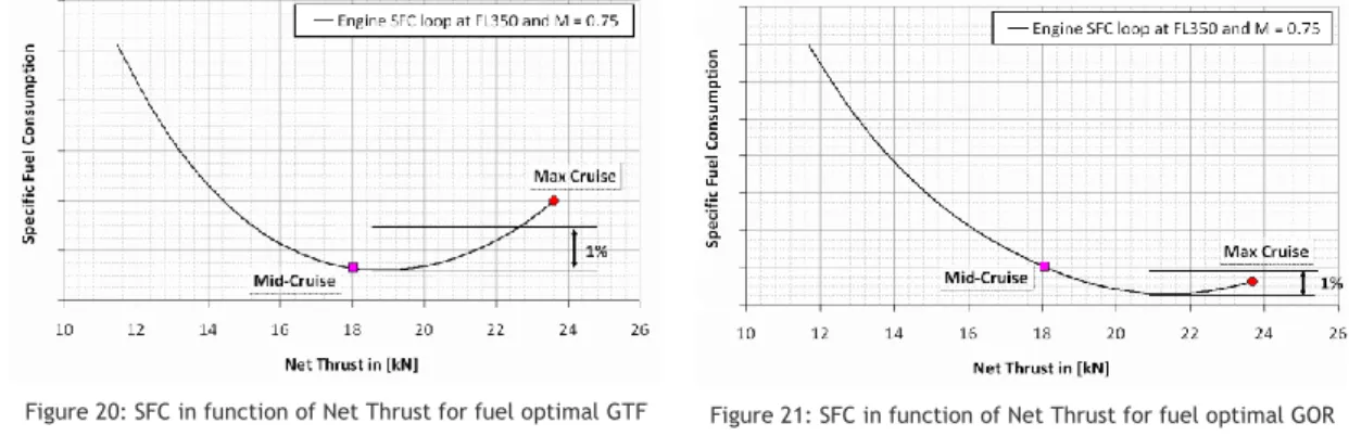
Figure 20: SFC in function of Net Thrust for fuel optimal GTF (Larsson et al. 2011). Figure 21: SFC in function of Net Thrust for fuel optimal GOR (Larsson et al. 2011). Figure 22: Block fuel in function of FPR (Guynn et al. 2009).
Figure 23: Block NOx in function of FPR (Guynn et al. 2009).
Figure 25: SFC in function of the OPR of IRA cycle at Max. Climb (Boggia & Rüd 2004). Figure 26: ΔSFC in function of OPR, for constant ST, with regeneration and cooling air bled before the RHE (Corchero et al. 2008).
Figure 27: ΔSFC in function of OPR, for constant ST, with regeneration and cooling air bled after the RHE (Corchero et al. 2008).
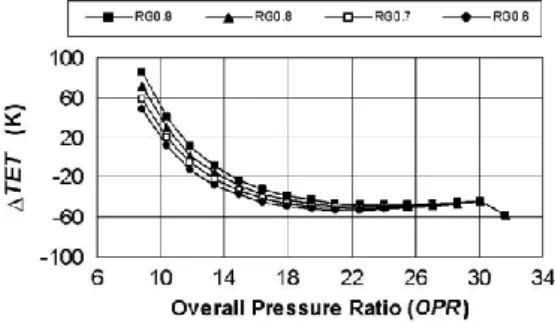
Figure 28: ΔTET in function of OPR for constant ST, with regeneration and cooling air bled before the RHE (Corchero et al. 2008).
Figure 29: NOx in function of OPR for constant ST, with regeneration and cooling air bled
before the RHE (Corchero et al. 2008).
Figure 30: ΔSFC in function of OPR for constant TET, with cooling air bled after the RHE (Corchero et al. 2008).
Figure 31: ΔST in function of OPR for constant TET, with cooling air bled after the RHE (Corchero et al. 2008)
Figure 32: SFC in function of OPR for constant ST in cruise conditions, with regeneration and cooling air bled before the RHE (Corchero et al. 2008)
Figure 33: Example of a Pareto Front (Ngatchou et al. 2005).
Figure 34: Optimization Results (maximization of the SFN and the minimization of the SFC) (Borguet et al. 2007).
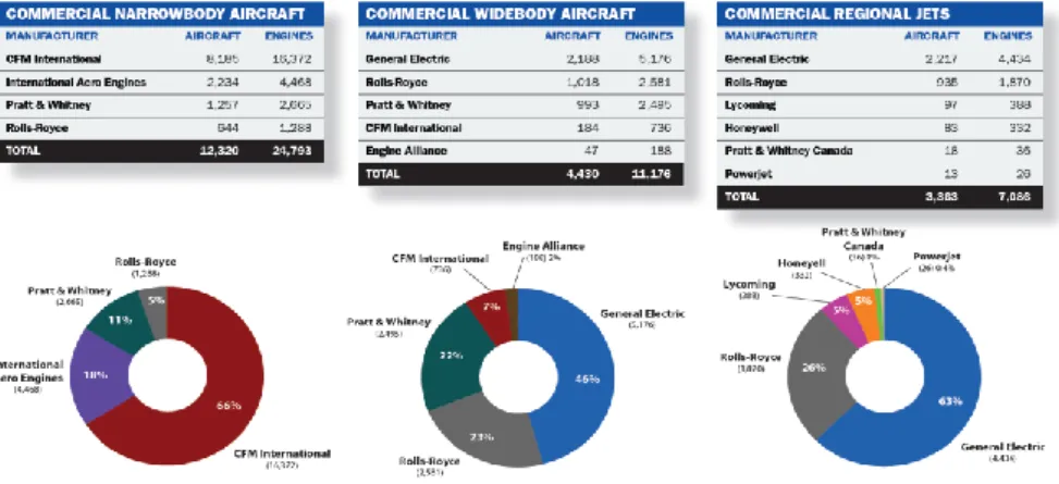
Figure 35: Engine Manufacturer Ranking (Analytics 2013).
Figure 36: Airbus/Boeing fleet by engine manufacturer (Analytics 2013). Figure 37: A320 market share in 2012 (Analytics 2013).
Figure 38: Regional Engine Market Share (Analytics 2013).
Figure 39: World Commercial Aircraft Engine Share (Analytics 2013). Figure 40: Engine market share by market group (Analytics 2013). Figure 41: Turbofan engine types (El-Sayed 2008)
Figure 42: Unmixed Turbofan (El-Sayed 2008). Figure 43: Mixed Turbofan (El-Sayed 2008).
Figure 44: Representative schematics of a Turbojet and a Turbofan (Cumpsty 2003).
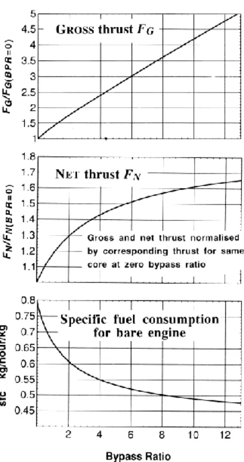
Figure 45: Estimated variation in thrust and SFC with BPR for a constant core (Cumpsty 2003). Figure 46: Estimated variation of SFC in function of the BPR for bare and installed engine (same conditions as Figure 45) (Cumpsty 2003).
Figure 47: Open Cycle gas turbine engine (A. Çengel & A. Boles 2006).
Figure 48: T-s and P-v diagrams of the ideal Brayton Cycle (A. Çengel & A. Boles 2006). Figure 49: Gas Turbine with regenerator (A. Çengel & A. Boles 2006).
Figure 50: T-s diagram of a Brayton regenerated cycle (A. Çengel & A. Boles 2006). Figure 51: PW1000G (Banda 2014).
Figure 52: PW1000G technical configurations (S. Arvai 2011). Figure 53: Features of the CFM Leap-x (S. Arvai 2011).
Figure 54: Layout of a two-spool turbofan engine (Adapted from (El-Sayed 2008)).
Figure 55: Layout of a two-spool turbofan engine with regenerator (Adapted from (El-Sayed 2008)).
Figure 56: Regenerator Station Numbering Figure 57: Engine Evaluation Strategy Diagram
Figure 58: Fs vs BPR with and without regeneration (TET 1500K and rpfan 1.2). Figure 59: Fs vs BPR with and without regeneration (TET 1800K and rpfan 1.2). Figure 60: Fs vs BPR with and without regeneration (TET 2100K and rpfan 1.2). Figure 61: Fs vs BPR with and without regeneration (TET 1500K and rpfan 1.5). Figure 62: Fs vs BPR with and without regeneration (TET 1800K and rpfan 1.5). Figure 63: Fs vs BPR with and without regeneration (TET 2100K and rpfan 1.5). Figure 64: Fs vs BPR with and without regeneration (TET 1800K and rpfan 1.8). Figure 65: Fs vs BPR with and without regeneration (TET 2100K and rpfan 1.8). Figure 66: Fs vs BPR with and without regeneration (TET 1500K and rpc 10). Figure 67: Fs vs BPR with and without regeneration (TET 1800K and rpc 10). Figure 68: Fs vs BPR with and without regeneration (TET 2100K and rpc 10). Figure 69: Fs vs BPR with and without regeneration (TET 1500K and rpc 15). Figure 70: Fs vs BPR with and without regeneration (TET 1800K and rpc 15). Figure 71: Fs vs BPR with and without regeneration (TET 2100K and rpc 15). Figure 72: Fs vs BPR with and without regeneration (TET 1500K and rpc 20). Figure 73: Fs vs BPR with and without regeneration (TET 1800K and rpc 20). Figure 74: Fs vs BPR with and without regeneration (TET 2100K and rpc 20). Figure 75: TSFC vs BPR with and without regeneration (TET 1500K and rpfan 1.2). Figure 76: TSFC vs BPR with and without regeneration (TET 1800K and rpfan 1.2). Figure 77: TSFC vs BPR with and without regeneration (TET 2100K and rpfan 1.2). Figure 78: TSFC vs BPR with and without regeneration (TET 1500K and rpfan 1.5).
Figure 79: TSFC vs BPR with and without regeneration (TET 1800K and rpfan 1.5). Figure 80: TSFC vs BPR with and without regeneration (TET 2100K and rpfan 1.5). Figure 81: TSFC vs BPR with and without regeneration (TET 1800K and rpfan 1.8). Figure 82: TSFC vs BPR with and without regeneration (TET 2100K and rpfan 1.8). Figure 83: TSFC vs BPR with and without regeneration (TET 1500K and rpc 10). Figure 84: TSFC vs BPR with and without regeneration (TET 1800K and rpc 10). Figure 85: TSFC vs BPR with and without regeneration (TET 2100K and rpc 10). Figure 86: TSFC vs BPR with and without regeneration (TET 1500K and rpc 15). Figure 87: TSFC vs BPR with and without regeneration (TET 1800K and rpc 15). Figure 88: TSFC vs BPR with and without regeneration (TET 2100K and rpc 15). Figure 89: TSFC vs BPR with and without regeneration (TET 1500K and rpc 20). Figure 90: TSFC vs BPR with and without regeneration (TET 1800K and rpc 20). Figure 91: TSFC vs BPR with and without regeneration (TET 2100K and rpc 20). Figure 92: Dominance Example (Engelbrecht 2007)
Figure 93: Pareto Front Example (Montoya & S. Mendoza 2011) Figure 94: Fs vs TSFC Pareto front results.
Figure 95: Median Trade-off results of the Pareto front for the conventional cycle. Figure 96: Fsreg vs TSFCreg Pareto front results.
List of Tabels
Table 1: Weight and Dimensions of a DDTF and a GTF configurations (Breu et al. 2011). Table 2: Independent variables used in the optimization process (Becker et al. 2013). Table 3: GTF weight distribution (Larsson et al. 2011).
Table 4: Open Rotor weight distribution (Larsson et al. 2011). Table 5: Second Setup Trade-Offs (Guynn et al. 2009).
Table 6: Results for both engines of the IRA cycle (Boggia & Rüd 2004). Table 7: Validation Test Main Specifications (Borguet et al. 2007) Table 8: Design Variables for the Optimization (Borguet et al. 2007). Table 9: Design Point Parameters (cruise) (Borguet et al. 2007).
Table 10: Optimal Solutions from the Pareto Front (Borguet et al. 2007). Table 11: Estimated Specifications for the PW1000G (Canada 2014).
Table 12: Estimated Specifications for the Leap Engine (CFM 2013; S. Arvai 2011). Table 13: Fixed Engine and Flight Characteristics (S. Arvai 2011; CFM 2013; Airbus 2012). Table 14: Assumed Component Efficiencies (Mattingly 2002).
Table 15: Multi-Optimization Setup for Conventional and Regenerated Cycles. Table 16: Pareto front results and nozzle status for the conventional cycle. Table 17: Median trade-off results of the Pareto front for the conventional cycle. Table 18: Pareto front results and nozzle status for the regenerated cycle. Table 19: Median trade-off results of the Pareto front for the regenerated cycle.
Nomenclature
Variables
Fs Specific Thrust
P Pressure
rpc Compressor Pressure Ratio
rpfan Fan Pressure Ratio
TET Turbine Entry Temperature
TSFC Thrust Specific Fuel Consumption
V Velocity
Acronyms
ADP Aerodynamic Design Point
ATFI Advanced Technology Fan Integrator
BPR Bypass Ratio
CE Cultural Evolution
CFD Computational Fluid Dynamics
CO2 Carbon dioxide
CP Specific Heat
CROR Counter Rotating Open Rotor
CV Constant Volume
DDTF Direct Drive Turbofan
DE Differential Evolution
DOC Direct Operating Cost
EAs Evolutionary Algorithms
ES Evolutionary Strategies
EVA Environmental Assessment
F Thrust
FPR Fan Pressure Ratio
GAs Genetic Algorithms
GTF Geared Turbofan
hm Equality Constrains
HPC High Pressure Compressor
HPT High Pressure Turbine
IC Intercooler
IR Intercooler and Regenerator
IRA Intercooler Recuperative Aero Engine
IRC Intercooler-Regenerative Cycle
K Kelvin
LA Los Angeles
LPC Low Pressure Compressor
LPT Low Pressure Turbine
LTO ICAO Landing and Take-Off Cycle
̇ Mass of air intake to the engine
̇ Mass of fuel added to the combustion
̇ Mass of hot air
̇ Mass of cold air
̇ Mass flow through the core
̇ Mass Flow through the engine
MaTES Matlab Turbine Engine Simulator
MO Multiple Objective
MOGA Multi Objective Genetic Algorithm MOHyGO Multi Objective Hybrid Genetic Optimizer
MOO Multi-Optimization Objective
MOP Multi-Objective Optimization Problem
MPL Maximum structural payload
NOx Nitrogen Oxides
NPSS Numerical Propulsion System Simulation NPGA Niched Pareto Genetic Algorithm
nx Dimensional chromosome
OPR Overall Pressure Ratio
Average Calorific Power of the Fuel
Specific Gas Constant
RHE Regenerative Heat Exchanger
SFC Specific Fuel Consumption
SFN Specific Thrust
SLS Sea Level Static
SO Single Optimization
SPEA Strength Pareto Evolutionary Algorithm
ST Specific Thrust
T Temperature
TOC Top of Climb
UHB Ultra Bypass Ratio
VEGA Vector Evaluated Genetic Algorithm VITAL Environmentally Friendly Aero-Engine WATE Weight Analysis of Turbine Engine
Wcool Core Mass Flow
WRTC Wave Rotor Topping Cycle
Subscripts
a External Conditions b Burner c before combustion f fuel g after combustion G GrossHPC Polytropic High Pressure Compressor
HPT Polytropic High Pressure Turbine
j Jet speed
jb Bypass jet
jc Core jet
LPC Polytropic Low Pressure Compressor
LPT Polytropic Low Pressure Turbine
m Mechanical N Net n Nozzle o Overall p Propulsive reg Regenerator S Specific t turbine th High thermal 01 Admission 02 Fan
03 Low Pressure Compressor
04 High Pressure Compressor
05 Combustion Chamber
06 High Pressure Turbine
07 Low Pressure Turbine
08 Hot flow leaving the regenerator
09 Exhaust gases leaving the regenerator
10 Nozzle Exit 11 Turbine Nozzle 12 Fan Nozzle
Greek Symbols
γ adiabatic index η EfficiencyΠ Pressure Ratio
Ψ, Φ Objective function
Γ Data type of elements
1. Introduction
1.1 Motivation
Reaching the final stage of my academic formation as an Aeronautical Engineer, it has always been my motivation to end it by studying a subject that satisfies my personal interest in my favourite area and, as well as contribute to the Aeronautical World with some future possibilities and visions.
It is my belief that for future progress of Mankind, the planet’s environment cannot be forgotten anymore. The environment should not represent the final barrier in any industrial/technological areas, avoiding them to develop, but it has to be taken as the main path to bring them to the next level. For now and for the future, they must give more environmental benefits and performances than their predecessors. The propulsion area must be one of the leading areas to give the example and show proofed results of this shifting. The Aeronautical World has its footprint in the planet’s environment and being one area where propulsion is more advanced, it is imperative that changes take the first steps there. The aircrafts are major fuel consumers and for that, a contribution in global warming is due to their activity. Designing new engines where the consumption is reduced significantly and the values of its performance are not compromised, are the plans of engine makers in the present and future. In that line of action, it has always been from my deepest interest the exploration of the new engine age in the aeronautical circle. To study future possibilities that put the bets even higher, always with the intention of contributing for a more eco-friendly and powerful engines that will take the planet in consideration.
1.2 Objectives
This dissertation was made with the main goal of studding the behaviour of an UHB Turbofan regarding specific engine parameters, with the possibility of a heat regenerator application. The aim is to verify if the brand new type of engine could deliver even less fuel consumption without compromising its performance, providing a set of viable and optimized options of configuration.
1.3 Framework
The increasingly manifestations of the planet’s environment are leading to a society that, more than ever, needs to pay attention to all the issues that dictate the future years of environmental stability. The aeronautical world, being one of the technological areas where innovation is imperative, must lead the example in all possible subjects. With this thesis is intended to minimize the gap between the concept of lower fuel consumption, thus
environmental friendly engines and the concept of better thrust and performance that a turbofan engine can deliver. Based on those ideas the future of aeronautical engines can reach higher levels of efficiency and performance, leaving behind the negative impact of polluting the planet, potentiating new forms of propulsion for even more ambitious projects.
1.4 Thesis Structure
The first chapter presents an introduction to this thesis, containing my motivation, the objectives for this study and the framework of the addressed theme.
The second chapter contains the state of the art. It will be made a literature review as well as relevant studies, following the conclusions.
The conceptual requirements are exposed on the third chapter. It will be presented the Turbofan Engine concept, the bypass ratio, the Brayton Cycle and the regenerated cycle. Also the new turbofan engines that will be released with the new airframes from Airbus and Boeing are presented.
The fourth chapter deals with the engine parameters. Requirements and assumptions are explained as well as the mathematical models. The first results of this thesis, the parameterization results are plotted and interpreted.
The fifth chapter opens the second phase of this thesis, where the Evolutionary Computational theory is presented to better understand the optimization concept that will be performed.
The sixth chapter emphasizes the type of algorithm that will be used in the multi-objective optimization.
The seventh chapter regards all the concepts of the multi-objective optimization. The problem setup is enunciated and the results will be calculated and plotted.
At last, the eighth and final chapter presents the thesis conclusions and reference for future possible works.
2. State of the Art
2.1 Literature Review
Many works have been developed in the last 30 years related to the possible ways to improve the performance of the Turbofan engines. Intentions of optimization of these kinds of engines have always been present after they proved in early years of service, their fantastic capabilities in commercial aviation.
The goals of reducing fuel consumption and recently cutting pollutant emissions turned the attentions once more to a successfully applied concept in ground systems for many years: regeneration.
With the recent UHB Turbofan engines for single aisle aircraft announced to be introduced in the market alongside with new the airframes in the near future, it is important to review the past and recent work investigations related with this type of engine. Different approaches of Turbofan optimization as well as the tools and technologies developed, are summarized in this section to help understand the path taken until the present days.
According to (Wulff & Hourmouziadis 1997), pollutant emissions in commercial aviation, have been a concern since the 1960s. The Meadows Report to the Club of Rome in 1972 made the industrialized countries sensitive to the issue. By the 80s, the continuous monitoring of the globe, identified global warming, the rising of the carbon dioxide in the content of the atmosphere and the depletion of the ozone layer over the Antarctic. As a result, governments and industry have responded with several research programs and the introduction of new improved products, with the major concern: the release of carbon dioxide and nitrogen oxides in the upper atmosphere and the stratosphere.
In the authors’ vision, operational changes in the airline flight profiles would benefit the reduction of NOx but would involve a major economic penalty. It is reminded that the total
exhaust emissions are a result of the overall efficiency of the aircraft. This includes the thermodynamic cycle of the engine as well the aerodynamic drag of the airframe.
It was proposed that the possibility of flying in lower cruise altitudes could bring environmental benefits. A flight from Berlin to LA was rematched to avoid cruising above tropopause. However, the results showed not viable, with a dramatic effect on range reduction by 20% and increasing the CO2 emissions by the same amount. This could only be
recovered if the aircraft were optimised for the specific operational conditions, which would require a complete new fleet of airliners. Ultra high bypass ratio engines with lower specific fuel consumption and wings with laminar flow control are pointed as the right direction of development.
In the engine field, the turbofan, being the source of the aircraft exhaust, can be target of a reduction in the fuel burn and overall emissions by better cycle efficiency and lower weight by 10%. A bypass ratio of optimum SFC is pointed by several authors to be near 13; however a reduction of the specific thrust and consequently a larger and heavier engine is obtained. The possibility of variable geometry is considered with a gearbox for the low pressure shaft. By the time of the present study it was concluded that alternative recuperated thermodynamic cycles or engines with pressure rise combustion didn’t appear to have any satisfactory improvements to justify the investment. Combustors are also considered, hypothesis like staged combustion, lean premixed prevaporized combustion and others are marked as potential options to the conventional method.
Due to the high emission of gases in the atmosphere in modern aviation, alternative cycles applied to the direct drive turbofan could be the answer to ensure more efficient and environmental friendly engines. The need of reducing fuel consumption is not only related to the rising costs of fuel, but also the idea of increasing the maximum payload. This is achieved by improving the global efficiency of the engine which is dependent of the propulsive and thermal propulsive efficiency. (Pasini et al. 2000) advance that the trend in actual propulsion systems is to use very high values for cycle maximum temperature, with an increasing discharge temperature due to operative modalities of the discharge nozzle, often working in off design conditions. This makes the heat discharged a strong influence in the system performance and heat recovery appears to be a way that needs further improvements and investigations. However there are limitations to implement this concept like the engine configuration and limitations, as weight, overall dimensions and reliability. This work studies the heat recovery in aircraft engines, evaluates the possible modalities emphasizing the regenerative process in the SFC as one of the most attractive processes for the future development.
Being the heat exchange process a direct influencer on the enthalpy drop in the exhaust nozzle, hence the velocity jet it is valid to say that the regeneration acts not only directly in the thermal efficiency, reducing the heat in the exhaust, but also in the propulsion efficiency by reducing the residual kinetic energy of the jet. These effects lead to a reduction of the specific thrust of the engine.
To evaluate if the regeneration process could bring benefits, a thermodynamic code was developed to simulate the thermal cycle and the main specific performances in different types of jet engines to evaluate the possible recoveries. It is also studied the heat exchanger configuration and the most appropriate location to apply it. “An analysis from the energetic point of view of the thermal cycle shows that a great amount of heat is wasted in the exhaust, and indicates how a recovery, total or more realistically partial, of this heat can lead to a greater efficiency of the system.” This code was applied to different types of aircraft engines like in a two separate flows turbofan engine. According to (Pasini et al. 2000)
the concept of regeneration in a turbofan is particularly interesting at high by-pass ratio. The majority of thrust is generated by the cold stream, while the gas generator offers the required power. Thus the enthalpy level before the exhaust nozzle of the gas generator can be lowered without losing great amount of thrust and still increase efficiency The maximum temperature was 1600K, an altitude of 10 000m, a flight Mach number of 0.8 and a fixed BPR at 7.
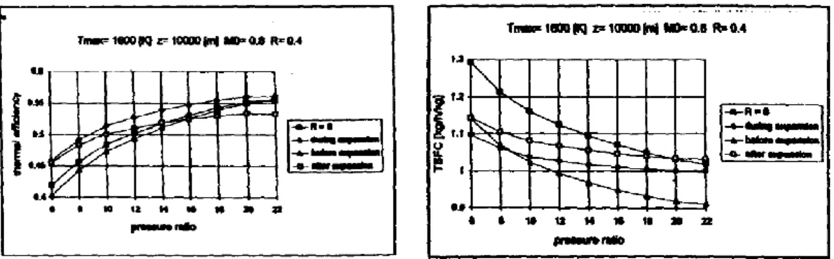
Results show that the recovery not only influences the process positively but also amplifies the influence of other operative parameters. The thermal efficiency when the heat recovery is present, reveals higher values of about 4% when R=0.5, while it rises to about 10% if R=0.7 as can be observed in Figure 1. These effects are
sensible at low pressure ratios. In fact, for pressure ratios about 20, the value of the thermal efficiency for which R=0.5 and the conventional one practically coincide. However above a certain value of pressure ratio (nearly 30) the heat can longer be transferred, while the pressure drop in the heat exchanger remains.
Regarding the heat exchange configuration, the heat can be exchanged between the two flows both in three different ways:
First case: the conventional one (heat subtracted before expansion in the nozzle);
Second case: heat is subtracted from gas while this is expanding in the exhaust nozzle;
Third case: heat is extracted from gas after this is expanded in the nozzle, nearly at external pressure, before being expelled into the atmosphere; The conventional heat transfer method revealed minimum level of fuel consumption compared to the others. However, the thermal efficiency is always better when the heat transfer is processed during the expansion (Figure 2). In the case of propulsive efficiency the results are not so clear. While at low pressure ratios, the heat subtracted during expansion seems convenient; at higher values of pressure ratio the heat exchange becomes more advantageous after the expansion. Figure 3 and Figure 4 describe the TSFC and ST in the different possibilities of expansion for R=0.4.
Figure 1: Thermal efficiency of a turbofan engine with regeneration (Pasini et al. 2000).
As conclusions, based on results, the authors enhance the regeneration as the possibility of improving the engine characteristics (lower pressure ratio and consequently lower levels of NOx). Problems of construction design must be further investigated to bring this next step to
life: “It is possible to build a heat exchanger suitable to be mounted on aircraft power plants, both for its size and weight, and also for the amount of heat exchangeable.” By the time, authors also predicted that “new engines can reach such values of BPR to be considered as a connecting bridge between turbofan and turboprop”. This was a reference to the new UHB turbofans that will be on service in the near future.
Another study, following alternative thermodynamic cycles applied to high bypass ratio turbofans was made by (Andriani & Ghezzi 2006). It was driven by the technical efforts in the last years in achieving high performance levels and low specific fuel consumption. This study carries an analysis of an optimization in thermodynamic cycles under the point of view of the maximum temperature at the turbine inlet due to new materials, cooling systems and pressure ratios. The authors state that NOx increases rapidly at combustion temperatures
above 1900K meaning that OPR and TET have to be kept within acceptable limits. The concept of regeneration is applied in this study, which permits reduce the fuel consumption without increasing pressure ratio and maximum cycle temperature. Intercooled staged compression process is also studied. Previous works showed that recovery heat process can improve fuel saving, especially in turbofan and turboprop engines.
Figure 2: Thermal efficiency as function of pressure ratio, with regeneration (Pasini et al. 2000).
Figure 3: TSFC as function of pressure ratio, with regeneration (Pasini et al. 2000).
Figure 4: Specific Thrust as function of pressure ratio, with regeneration (Pasini et al. 2000).
To estimate the capabilities of the regeneration, a thermodynamic code was developed to simulate different operative conditions, as flight level, flight speed Mach number, and engine characteristics, as pressure ratio, bypass ratio, turbine
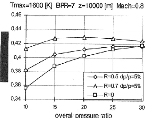
inlet temperature, efficiency of regeneration, etc. With this code it possible to determine the main propulsion and thermodynamic characteristics, like specific thrust, heat exchanged, thermal/propulsion and global efficiency and specific fuel consumption. The turbofan considered (Figure 5) had a BPR equal of 7, a TET of 1600K and a flight Mach number of 0.8 at 10
000m. Three cases were evaluated: the conventional engine with no regeneration (R=0), and two cases with regeneration of 50% and 70% (R=0.5 and R=0.7), both with a pressure drop of 5% on each side of the heat exchanger. The next figure shows the graphics of specific thrust and specific fuel consumption obtained with the considered configuration.
The results with regeneration, reported in Figure 6, show a higher thermal efficiency, than the conventional case of about 4% (R=0.5) and 10% (R=0.7). However, these results are valid for low pressure ratios. If the pressure ratio is increased to 20, the thermal efficiency with R=0.5 coincide with the conventional case. Above 30, the regenerative process exhibit a thermal efficiency worse than the conventional cycle. This is due to the impossibility of exchanging heat above a certain pressure ratio. The pressure drop in the heat exchanger remains,
and so the configuration with exchanger is not viable. Regarding the behaviour of TSFC, it is noticed a considerably decrease in fuel consumption, especially at low values of pressure ratio. The same cannot be verified for high values of pressure ratio, where the conventional configuration, show the same values of the regenerated configuration. High values of pressure ratios are usually reached by modern turbofan to take advantage of the high TET. “It seems possible to obtain, if not lower, same levels of SFC as conventional case but at lower pressure ratio”(Figure 7). The authors suggest that this can be achieved, using a smaller, simpler and cheaper compressor. Moreover, the size of the heat exchanger should not be excessive, not larger than the fan considering that at high values of BPR, the mass flow rate of the gas generator, and consequently the flow through the heat exchanger, is much smaller than the secondary.
Figure 5: Turbofan Engine with regeneration (Andriani & Ghezzi 2006).
Figure 6: Thermal Efficiency in function of pressure ratio, with and without regeneration (Andriani &
Finally, the propulsion efficiency is superior than the conventional situation (Figure 8) and once more at lower pressure ratios, due to the reduced gas kinetic energy in the exhaust, since the heat extracted has been subtracted in the heat exchanger.
The intercooling, by dividing the stages of compression, gives the possibility of cooling down the air temperature between the exit of one stage to the inlet of the following. The work necessary to improve air pressure is less, the compressor absorbs less power providing greater enthalpy drop in the nozzle for thrust. Both practice of the regeneration with intercooling is suggested as a way to obtain a greater output power and a lower specific consumption at a greater thermal efficiency. The main drawback of this configuration is the weight and size imposed by aero engines. The results cannot be compared to the regeneration because it was simulated at zero altitude and zero flight Mach number.
For conclusions, (Andriani & Ghezzi 2006), enhance the problems of size, weight and integration with the engine and the aircraft in both concepts (regeneration and intercooling). Should the problems cited above be solved, and the benefits are clear in the performances. “The introduction of regeneration in a turbofan engine has increased the thermal and propulsion efficiencies leading to a reduction of the specific fuel consumption of more than 10% at low pressure ratios. The price to pay is a reduction of the same order of the specific thrust.” The authors suggest that this loss can be counteracted by the intercooled staged compression process.
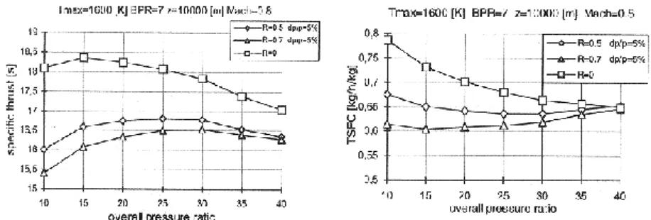
Figure 7: Specific Thrust and Specific Fuel Consumption in function of OPR, with and without regeneration (Andriani & Ghezzi 2006).
Figure 8: Propulsion Efficiency in function of OPR, with and without regeneration (Andriani & Ghezzi 2006).
The introduction of heat exchangers for engines of two spools could be one of the solutions for better environmental engines. This possibility was studied by (Lebre & Brójo 2010). The reduction in the specific fuel consumption (SFC) and the increase of efficiency and specific thrust (ST) are compared to the penalty introduced by the extra weight. The work compares the performance parameters of a conventional engine against three alternative configurations: use of intercooler, regenerator or both. The comparison shows the influence of each parameter in specific fuel consumption, specific thrust and thermal efficiency. This numerical analysis uses a conventional turbofan engine with 50 000lbs of thrust. Assumptions applied were a steady and one–dimensional flow; perfect gas with calorically perfect gas and in isentropic conditions. External mechanical power is neglected; with cooling air but not bleed. The turbine entry temperature (TET) is 1500K for a specific thrust of 200 at a cruise altitude of 10 668m and Mach 0.8. The OPR is 26, the fan pressure ratio (FPR) is 1.71 and the bypass ratio (BPR) is 5.
In the engine with regenerator, the heat exchanger objective is to heat the air leaving the high pressure compressor with the heat from the exhaust gases. By introducing this component, the required fuel in the combustion is reduced. This is due to the increase of the air temperature before entering the burner, reducing temperature difference between the entry and exit of the burner. The temperature of the exhaust gases leaving the turbine is generally higher than the temperature of the air leaving the compressor. Using this, it is possible to heat the high pressurized air at the exit of the compressor by transferring heat to it from the exhaust in a counter-flow heat exchanger also known as a regenerator.
The engine with intercooler is a type of heat exchanger that is applied between the low and high pressure compressors. The air that passes through this system is cooled before entering the high compressor; consequently the work required for compression is reduced.
At last, the engine with intercooler and regenerator (IR), is characterized by a SFC lower than the conventional with higher thermal efficiency
Results show that the engine with better specific fuel consumption is the engine with regenerator. In contrary, the engine with only intercooling has the worst results, even when compared with the conventional engine (Figure 9). The authors alert that the variation of FPR has impact on ST and on the SFC. The variation of the specific thrust in
function of the FPR is equal for all types of engines (Figure 10). It is also observed that the SFC is not modified by the low pressure compressor (LPC) ratio on the conventional and regenerated engines as would expected. By raising the OPR in the conventional engine, it is observed that has the same values of SFC as in the engine with intercooler (Figure 11).
Increasing OPR provokes a decrease in SFC. Engines with regeneration or IR cycles the opposite is observed, “An increase in the overall pressure ratio leads to an increase in specific fuel consumption”. This can be observed in Figure 12 along with the correspondent ST.
The thermal efficiency is a parameter that increases with the use of the regenerator. From the engines studied, results show that engines with regeneration have higher efficiencies than the engines without it (Figure 13). The FPR is a parameter that influences thermal efficiency which can be increased for low values of FPR. Thermal efficiency does not suffer variation with LPC in the case of the absence of the
regenerator. Although an increase in the LPC ratio leads to an increase in SFC and a decrease in thermal efficiency. Another important parameter observed was in the case of a regenerator being present; the increase of OPR has a negative influence on thermal efficiency, while without it the opposite occurs.
The conclusions of this work revealed that the engine only with intercooler has the worst SFC results and lower thermal efficiency. The engine with intercooler and regenerator has better SFC and thermal efficiency compared to the conventional engine used in this study. “But it is not the one with better values of specific fuel consumption and thermal efficiency. The engine with only regeneration has the lowest values of specific fuel consumption and the highest for thermal efficiency.” The IR also has lower values of performance compared to the
Figure 10: ST in function of FPR (Lebre & Brójo 2010). Figure 11: SFC in function of FPR (Lebre & Brójo 2010).
Figure 12: SFC and ST in function of OPR (Lebre & Brójo 2010).
Figure 13: Thermal Efficiency in function of OPR (Lebre & Brójo 2010).
engine with only regenerator. “With this behaviour can be deduced that the influence of the regenerator is larger than the intercooler for the range of parameters considered.” The engine with regenerator is pointed to be the best in SFC and thermal efficiency.
(Humhauser 2005) points that in the near future, the idea of aiming better thermal/propulsive efficiency with more fuel, noise and efficient components, will have to take into account the possibility of increasing the bypass ratio and reduce the fan tip speeds as well as the jet velocities. These measures will help the enhancement of propulsive efficiency and noise reduction.
Regarding the thermal efficiency, (Humhauser 2005), suggests that increasing the overall pressure ratio (OPR) and the turbine entry temperature (TET) is necessary to achieve the desired goals. The research in improved cores may counteract the weight penalties from enlarging BPR and fan diameters. Expectations of values for OPR and TET, for long range applications are 50 and 2000K-2100K respectively.
The geared turbofan concept (Figure 14) is the answer suggested by the author for aiming those kinds of bypass ratios and OPRs. “Since more than 15 years, Pratt and Whitney America (P&WA), Pratt & Whitney Canada (P&WC), Fiat Avio and MTU are jointly working on the development of geared turbofan engine technologies for small and large thrust class applications.”
(Riegler & Bichlmaier 2007) make an analysis of the concept and the development status of the geared turbofan. The concept of applying a speed reduction gear on the low spool of a two-shaft engine between the slow spinning side (Fan) and the fast spinning side (LPC and the LPT) have been investigated for two decades. It provides the possibility of an additional degree of freedom which benefits the optimization of the turbo machines independently, keeping high work extraction on a low number of stages. The aerodynamic losses can be
lowered and putting efficiencies in higher values. By de-coupling the Fan speed from the rest of the low spool machinery, this principle intention is to further increase the bypass ratio in order to improve propulsive efficiency. As a consequence, TSFC decreases as well as noise and weight. It can be applied to long range missions and wide body aircrafts, but mid-range single aisle aircrafts and regional jets are also considered.
The maintenance costs benefits due to reduced stage and airfoil count are most valued by the operators as well as the 70% reduction weight of the LPT which counteracts new or heavier components of the engine.
This concept represents the next step in performance, emissions (due to low fuel burn), noise and does not impose unreasonable risk to the customer (Figure 15), as a more revolutionary step like the counter-rotating turbo machinery concept. However the open rotor concepts can provide higher TSFC and fuel burn benefits, they are struggling with achieving noise requirements and the technology
improvement is still one decade away. There is a need of dramatic changes of engine/airframe integration.
Therefore, according to (Riegler & Bichlmaier 2007), the GTF “is the only turbofan engine concept which allows significant reduction in fuel burn, maintenance cost and noise at the same time, and which will be technology ready near-term to support EIS dates the aircraft manufacturers and airline customers are envisioning.”. From the author’s view it is stated that “the GTF engine is THE best concept for the demands of the market”.
An optimization study of the GTF engine is performed by (Breu et al. 2011). In this work the targets are: minimize the emissions, and compare the results against a direct drive turbofan for a given mission. Mechanical design analysis is also performed so it can be possible to predict the effects of the weight engine and the nacelle drag.
This analysis includes a preliminary design and evaluation of the aircraft generated in the house code GISMO, which will provide performance and nacelle drag results. Regarding the engine, the performance is evaluated by GESTPAN (generic tool for gas turbine design and analysis). Weight and dimensions are performed by the design tool WEICO. The optimization of the engine was assessed by the optimization software ISIGHT. The parameters chosen to apply in the optimization software were: BPR, fan pressure ratio and the overall pressure ratio.
Figure 15: Predicted Parameters of the Geared Turbofan Technology (Riegler & Bichlmaier 2007).
In the design point of the engine it is noted that an increase of BPR will origin a bigger fan diameter, which will influence drag and weight in a negative way. Despite of the reduction in fuel consumption while the BPR increases, the author’s alert for the fact that for some values of BPR more stages in the LPT are added, thus weight will be added to the engine. These effects will be more incisive in the direct drive turbofan, in such a way that it is stated: “it is worth considering going to a slightly lower BPR than the optimum if the part count can be reduced”. The fuel burn will decrease with the increasing of the OPR, although this was kept constant for both engines (40) as well as the TET (1850K).
Results indicate that 3% lower fuel consumption for the mission is achieved for the GTF. In terms of bypass ratio it does not differ too much for both engines (12.5 for the DDTF and 13.5 for the GTF), however the number of stages of the HPC in the DDTF will be significantly higher adding extra weight. The total engine weights are 3100kg for the DDTF and 2880kg for GTF, giving a 220kg of weight saving on the geared configuration (Table 1).
Therefore it can be concluded that all characteristics combined with other structural innovations can potentially deliver fuel benefits for GTF engine. The weight reduction and the lower stage loading with higher component efficiencies prove to be the next step of the turbofan market.
The two future engine concepts (Geared Turbofan and Open Rotor) are often compared in similar conditions. While the first is the next step in ducted turbofans, the other brings a more revolutionary arquitecture design. Benefits and drawbacks meet these two kinds of engine and are exposed by (Becker et al. 2013). This investigation considered a 150 passenger short range airliner, where the GTF is a standard two shaft engine while the Open Rotor is a counter rotating aft mounted three shaft pusher. Both concepts are numerically optimized for a set of discrete operating points, where the component efficiencies and cooling technology of the core engines are aligned in the same technology level. It is intended to analyse fuel efficiency of overall aircraft as well as weight/drag estimations. The engines are submitted to a flight mission, where cruise condition was selected as the master design point since it is the most important flight condition regarding consumption.
Table 1: Weight and Dimensions of a DDTF and a GTF configurations (Breu et al. 2011).
The optimizer modified a set of independent variables such as LPC, HPC pressure ratios, TET and BPR in order to find the optimal solution in cruise fuel efficiency (Table 2). In the GTF the fan pressure ratio was automatically iterated to achieve optimal velocity ratio between the core and bypass nozzle.
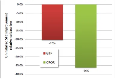
The results feature a GTF with a bypass ratio of 12.2, with an ideal fan pressure ratio of 1.38. The estimated weight of this propulsion system is approximately 3201kg with a smaller core and a lighter nacelle configuration, while the CROR engine exhibits a predicted mass of 4097kg. The authors suggest that an increase in weight reduction is possible by applying composite materials in the fan to overcome the penalty of its increased size. The superior weight of the open rotor has a consequence in the reduction of the maximum structural payload (MPL) by 1390kg, whereas a minor increase of the MPL can be verified in the GTF. The BPR of the CROR is seven times larger than the GTF resulting in a propulsive advantage. That advantage is seen in a SFC improvement relative to the baseline model by 36% against 20% from the GTF (Figure 16). The OPR and TET were kept constant at 46.9 and 1509K.
The flight mission executed by these engines was over 4465Km. The GTF was capable of reducing 19.4% relative to the baseline model and the CROR achieved the 30.2% fuel cut. The results from the GTF are superior to the claimed by Airbus and Pratt & Whitney for the A320Neo equipped with the PW1100G.
Table 2: Independent variables used in the optimization process (Becker et al. 2013).
As conclusions from this work, (Becker et al. 2013) state that despite the weight penalty of 28% of the CROR compared to the GTF, its propulsive efficiency outweighed the issue with a 12-13% fuel burn cut over the GTF. However engine installation effects of the study need to be more developed to assure the described benefits, which sustains (Riegler & Bichlmaier 2007) conclusion on this topic. Nevertheless, the authors point the open rotor as the next answer over the near term new engines (PW1000G and LEAP-X) with the potential to offer even more benefits for the 2025 engine generation.
Regarding the GTF, this kind of engine suffers a penalty in drag and weight if conventional nacelles are used. New composite materials and engine-airframe integration like embedded engines are pointed to help circumvent these drawbacks. The increase in BPR may lead to a small core size, in contrast with the cruise and top of climb temperatures that will be superior to the conventional values. Technology developments are required to improve the specific power of the core.
Another similar study was performed by (Larsson et al. 2011), in which a geared open rotor and an ultra-high bypass ratio geared turbofan engine are compared and assessed. The priorities were minimizing the block fuel through the specific thrust level and the resulting engine emissions from a flight mission with a 2020 predicted technology. This multidisciplinary analysis contains computational models that capture the engine performance, aircraft design/performance as well as the direct operating costs and emissions, using the EVA1 code. The mechanical and aerodynamic design, engine component
weight and dimensions were worked by the design tool WEICO. Both of this programs were integrated together to work with a commercial integration and optimization environment. The GTF of this study is a two shaft configuration with a conventional reduction gearbox. On the other side, the open rotor is a geared contra-rotating pusher configuration with a core of a two spool turbojet; the propulsor consists in a power turbine that drives two contra rotating propellers with swept blades. A planetary gearbox is between the propellers and the power turbine. OPR and TET were kept constant with the purpose to provide mid-cruise conditions as well as optimal BPR for SFC. The studies relatively to a direct turbofan for the year 2020 showed that reducing the specific thrust can improve the propulsive efficiency but worsens the transmission efficiency, introducing a constraint in the search for the optimal engine design. At FPR of 1.2 there’s no thermodynamic benefit from further reducing the specific thrust. Similar results were obtained in the fan and LPT polytropic efficiencies (Figure 17).
1A code developed in (Kyprianidis et al. 2008) for environmental assessment of novel propulsion
Considerations were made:
Raising the efficiency of the fan and LPT directly improves SFC as well as the optimal BPR value at a constant specific thrust.
Limited SFC benefits may be acquired by reducing specific thrust beyond a fan pressure ratio of 1.45.
Predictions from the authors for the year 2020, reveal that by reducing the specific thrust in a direct drive fan conventional core engine for long haul applications, the block fuel benefits have a consequence of 10 % increase in fan diameter and 4% reduction in FPR (translating in a 14% reduction in specific thrust) and resulting in a 2% improvement uninstalled SFC at mid-cruise. The engine weight would increase by
17% along with the higher nacelle drag and the resultant block fuel benefit would only be of 0.85% (Figure 18). “It can therefore be concluded that the commercial competitiveness of reduced specific thrust turbofan designs will largely depend on how the aviation market evolves in the years to come until 2020.” According to (Larsson et al. 2011), the block fuel benefits are highly dependent on the engine thrust to weight ratio. Therefore, the engine design for minimum block of fuel represents a
trade-off between improving thermal and propulsive efficiency and reducing engine weight and nacelle drag, knowing that depends primarily on specific fuel consumption, engine installed weight and nacelle drag.
Figure 17: Estimated 2020 uninstallled SFC benefits from reducing ST in a conventional turbofan engine with optimal LP and core
(Larsson et al. 2011).
Figure 18: Estimated 2020 block fuel benefits from reducing ST in a conventional turbofan engine for long range applications (Larsson et
Regarding the engine temperatures, the authors also show the trends for engines designed for long haul applications. These new engines will have new temperatures for maximum combustor outlet and turbine blade metal. Following is the Figure 19 that predicts the evolution of the turbine entry temperatures until 2020 and the respective technology of the blade material.
Results show that the open rotor concept provides substantial fuel saving potential compared to the ducted fans, it gives 14% lower SFC than the GTF. Although heavier in weight, the reduced SFC and nacelle drag can compensate the drawbacks. The variation of the open rotor bypass is bigger than the GTF in different operating points. In mid-cruise conditions, the GTF can deliver the lowest SFC as possible; the same cannot be achieved in the open rotor. This is verified in off-design conditions, where the propeller efficiency is reduced as the engine is throttled down (Figure 20 and Figure 21).
In terms of weight for both engines, the large fan of the GTF is a major player to the total weight, whereas the open rotor, the major part of its weight results from the propellers, associated structural components and a heavier gearbox. It can be observed that the open rotor engine core is roughly 50 kg heavier, due to the intermediate pressure turbine that is not present in the geared engine (Table 3 and Table 4).
Figure 19: Turbine blade material technology chronology and maximum TET (Larsson et al. 2011).
Figure 20: SFC in function of Net Thrust for fuel optimal GTF (Larsson et al. 2011).
Figure 21: SFC in function of Net Thrust for fuel optimal GOR (Larsson et al. 2011).
A sensivity study was made to evaluate the block fuel impact in component efficiency/technology. Results show that the sensitivities from the changes in components efficiency are superior in the GOR than for the GTF. Varying component efficiencies, the core velocity varies and the velocity ratio moves away from the optimal point. Since the jet velocities for the open rotor are lower, the sensivity figure is higher for the propellers than for the fan regarding that a larger part of the thrust is produced by the propellers compared to the fan.
”With CO2 emissions being directly and linearly correlated with fuel flow and hence block
fuel, it can easily be concluded that the GOR concept offers a reduction of up to 15% in CO2”.
As conclusions, despite the heavier engine of the open rotor, the reduced SFC and nacelle drag makes up for this. However, the mid cruise operating point is not at the bottom of the SFC loop. A precise trade-off is necessary regarding the size of the engine and the design point for the propellers, since for short haul aircraft, the major part of the flight is spent in climbing to cruise, rather than cruising. It is also stated that 6% lower in DOC can be expected from the geared open rotor concept than from the GTF at current fuel prices. Although the exposed benefits of the GOR, the authors remind that introducing a new concept in the market has large risks, such as: delayed introduction of the product to the market, increased development costs and late design changes. So they leave the question for future investigations: “Can the potential reduction in DOC outweigh the technological risks involved in introducing an open rotor configuration into the market.”
A study performed by (Guynn et al. 2009) enhance the clear benefits of increasing the bypass ratio in terms of SFC, however these benefits may not translate into aircraft system level benefits due to integration penalties. With that idea in mind, the primary objective of this study was to determine if the TSFC and noise improvements of high values of BPR could really translate into overall aircraft system benefits. This study addresses the design trade space for advanced turbofan engines applied to the single-aisle transport (737/A320) replacement entering service in the 2015-2020 time frames. It is possible that the engines for the 737/A320 replacement will continue the trend of raising the BPR, leading to ultra-high bypass ratio (UHB) engines. The benefits of higher bypass associated technologies such geared fan drive, can bring improved propulsive efficiency. However bypass ratios at which fuel consumption is minimized may not require geared technology, however a geared fan drive
enables higher bypass ratio designs which result in lower noise, all of these pros and cons are considered in this study. “The 737/A320 class considered in this study represent a significant portion of the global airline fleet. Sixty-five percent of the new aircraft produced over the next 20 years are projected to be in this class. Advances made to reduce the noise and emissions of these aircraft could provide a considerable positive contribution to the goal of minimizing the future environmental impact of aviation.”
The approach consisted in the development of a series of analytical engine models, apply them to an airframe and assess the overall performance and noise characteristics. The main parameter of interest to the study was the fan pressure ratio (FPR), knowing that the BPR is inversely proportional to fan pressure ratio. As fan pressure ratio is reduced, to maintain thrust fan mass flow must increase, which results in higher bypass ratio. The projected engine models for the 2015 time frame were developed by a design team with a common design approach and set of technologies assumptions to enable this consistency. The baseline model was a two spool separate turbofan. Variations like fan drive approach (geared vs direct); FPR, the low spool-high spool compression work split, the type of fan nozzle (fixed or variable geometry), OPR and Mach number were considered. All the engines were developed with the same Aerodynamic Design Point (ADP), which is Mach number, altitude and thrust, as well as equal OPR with two variants: “low work” and “high work”. The “low work” engines have a lower pressure rise across the low pressure compressor (consequently higher pressure rise across the high pressure compressor), the inverse situation is the “high work” The ADP selected was a nominal top-of-climb (TOC) for the airframe. To meeting a thrust target at TOC conditions, a SLS thrust target of 23 000lb (hot day, ISA+27°F) was implemented. The low fan pressure ratio engines inherently have a greater loss of thrust with airspeed, than high fan pressure ratio engines. To assure the required thrust for ADP, the low FPR engines are operated at higher temperatures. However, high temperatures on the low FPR engines could lead to a reduced hot section life and greater maintenance than high fan pressure ratio engines. The engine life and maintenance influences were not studied.
The numerical tools used for this evaluation were the Numerical Propulsion System Simulation (NPSS) for the cycle analysis of the engines and the Weight Analysis of Turbine Engines (WATE) for the aeromechanical characteristics of the engine weight; emissions were obtained from a correlation developed by NASA combustor technologists during the latter stages of NASA’s Ultra–Efficient Engine Technology Program.
This investigation resulted in three different sets of engines having different design rules and assumptions. Each set contains 16 different configurations for a total of 48 engine/airframe combinations. The primary differences between the three sets were OPR at ADP and ADP/cruise Mach number. In the first set all of the engines were designed with an OPR of 32 at TOC similar to of the CFM56 engine. Higher OPRs can lead to smaller compressor blades, although there are limits to how small compressor blades can be manufactured and how
efficient they are. The second set of engines was made to obtain an OPR increase to 42, changes were made in LPC and HPC pressure ratios. The two first sets were designed with a Mach number of 0.80. (Guynn et al. 2009) say that in order to increase fuel efficiency, some suggest that the replacement of the 737/A320 families can be designed to fly significantly slower. Due to environmental and economic pressure, the airliners may be willing to lose some productivity (speed) for reduced fuel consumption. Following the same idea, the last set of engines was developed with a reduced Mach number to 0.72 to evaluate the performances.
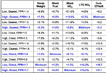
The results of the ramp weight show that there is a clear preference for high work geared designs at fan pressure ratios up to 1.5 and for low work direct drive engines at higher fan pressure ratios. The weight penalty associated with the low FPR is consistently in the three sets. All the three sets reduce the ramp weight with a higher FPR. Regarding the block fuel, it is observed that the worse values are for engines with very low FPR. The minimum block fuel consumption occurs in the 1.55 to 1.6 FPR range. Geared engines are preferred bellow a fan pressure ratio of 1.5, the same as for the ramp weight (Figure 22). In the three sets the fuel
consumption is reduced by high OPR and lower cruise Mach number.
Like the ramp weight, the emissions of NOx decrease with the increasing fan pressure ratio,
being the geared configuration beneficial up to FPR of 1.6 (Figure 23). All the variations of the
parameters are well observed in the results, but the noise with the FPR variation is superior comparing the variation in the weight, fuel consumption or emissions.