Proceedings
of the
I
nternational
Fire
S
afety
S
ymposium 2015
Coimbra, 20-22 April, 2015
Portugal
Hot Disk
®Organizers:
cib - International Council for Research and Innovation in Building Construction
UC - University of Coimbra
albrasci - Luso-Brazilian Association for Fire Safety
Editors:
João Paulo C. Rodrigues George V. Hadjisophocleous Luís M. Laím
Proceedings of the
International Fire Safety Symposium 2015
Organizers:
CIB - International Council for Research and Innovation in Building Construction UC - University of Coimbra ALBRASCI - Luso-Brazilian Association for Fire Safety
Authors:
II
Proceedings of the International Fire Safety Symposium 2015
held at the Department of Civil Engineering of the University of Coimbra, Portugal 20th-22nd April 2015
ISBN 978-989-98435-5-4 ISSN 2412-2629
A Simposium organised by
International Council
for Research and Innovation in Building and Construction (www.cibworld.nl)
University of Coimbra (www.uc.pt)
ALBRASCI
Luso-Brazilian Association for Fire Safety
(http://www.albrasci.com)
All rights reserved. No part of the publication may be reproduced, stored in a retrieval system, or transmitted in any form or by any means, electronic, mechanical, photocopied, recording or otherwise, without prior permission of the Publisher.
IFireSS – International Fire Safety Symposium
Coimbra, Portugal, 20
th-22
ndApril 2015
29
PARTIALLY ENCASED SECTION: STRENGTH AND STIFFNESS UNDER
FIRE CONDITIONS
Paulo Piloto Professor IPB – Bragança
Portugal
David Almeida
Student IPB – Bragança
Portugal
A.B Ramos-Gavilán
Professora U. Salamanca
Spain
Luís M.R. Mesquita
Professor IPB - Bragança
Portugal
ABSTRACT
Fire resistance of partially encased sections (HEB and IPE) depends on the temperature evolution during fire exposure. Eurocode 4, part 1.2 [1], proposes the assessment of the cross section using the method of the four components under fire (flanges, web, concrete and reinforcement). This study aims to assess the balanced summation model of Eurocode (informative annex G) with respect to the plastic resistance to axial compression and the effective flexural stiffness of the cross section with respect to the weak axis. New formulae will be proposed to evaluate fire resistance, based on new simple formulas to determine the flange average temperature, the residual height and average temperature of the web, the residual cross section and average temperature of concrete, the reduced stiffness and strength of reinforcement. The advance calculation method was used to validate new and safe formulae, based on the analysis of the cross section totally engulfed in fire.
Keywords: Partially Encased Sections; Fire Resistance; Simplified Calculation Methods; Advanced Calculation Methods.
1. INTRODUCTION
Partially encased section members are usually made of hot rolled steel profiles, reinforced with concrete between the flanges. The composite section is responsible for increasing the torsional and bending stiffness when compared to the same section of the steel profile. In addition to
Corresponding author – Department of Applied Mechanics, Polytechnic Institute of Bragança. Campus Santa Apolónia, ap. 1134, 5301-857
Paulo Piloto, David Almeida, A.B Ramos-Gavilán and Luís M.R. Mesquita
30
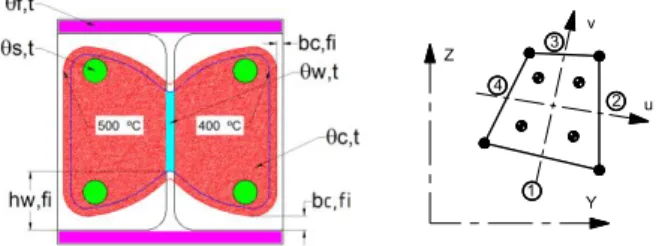
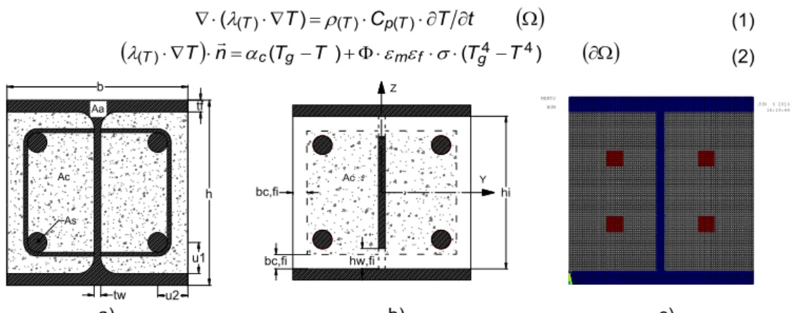
these advantages, the reinforced concrete is responsible for increasing the fire resistance. The fire resistance of partially encased sections depends on the temperature effect in each component. According to Eurocode 4, Part 1.2 [1], the fire resistance can be evaluated by the four components method (the flanges of steel profile, the web of steel profile, concrete and reinforcement) when submitted to standard fire and for different fire resistance classes (R30, R60, R90 and R120). This study aims to assess the parameters of Annex G: average temperature of the flange, part of the web to be neglected, residual area and average temperature of the concrete and reducing reinforcement characteristics. To study the effect of fire, two types of cross section were selected, corresponding to set of cross section geometry: IPE range from 200 to 500 and HEB range from 160 to 500. Figure 1 represents the generic partially encased section, identifying the four components and showing the finite element mesh used. The nonlinear solution method (ANSYS) was used to evaluate the temperature field. The finite element method requires the solution of Eq. 1 in the cross section domain and Eq. 2 in the boundary. In these equations: T represents the temperature of each material; defines specific mass; Cp(T) defines the specific heat; (T) defines the thermal conductivity; c specifies the
convection coefficient; Tg represents the gas temperature of the fire compartment; specifies
the view factor; m represents the emissivity of each material; f specifies the emissivity of the
fire; specifies the Stefan-Boltzmann constant. It is assumed the use of standard fire curve ISO834 [2] around the cross section (4 exposed sides).
((T) T) (T) Cp(T) T t (1)
( )T
n (T T ) (T4T4)
g f m g
c
T
(2)
a) b) c)
Figure 1: Partially encased section: Model, parameters and approximation.
2. PARTIALLY ENCASED SECTIONS
The cross sections were designed according to the tabulated method applied to column design in fire conditions [1], considering the minimum reinforcement ratio As (AsAc), the minimum
u1 u2 tw b h Ac Aa tf As Ac bc,fi bc,fi hw,fi Z Y hi X Y Z JUN 6 2014 16:19:44 ELEMENTS
Paulo Piloto, David Almeida, A.B Ramos-Gavilán and Luís M.R. Mesquita
31
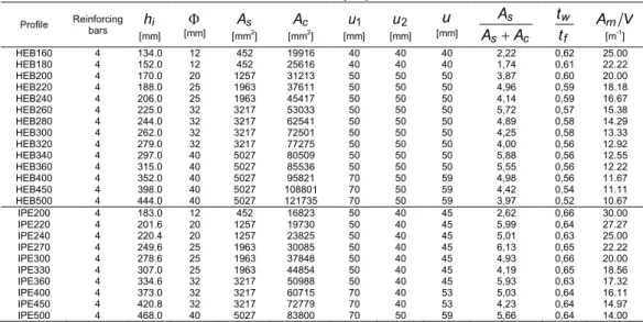
concrete cover dimensions (u) and the minimum cross section dimensions (b,h).Table 1 presents the main dimensions, in particular the number of reinforcing bars, the diameter of each rebar and the concrete cover dimensions in both principal directions, u1,u2.
Table 1- Section properties.
Profile Reinforcing bars hi [mm]
[mm] [mmAs2] [mmAc2] [mm] u1 [mm] u2 u
[mm] s c
s
A A
A
twf
t Am V
[m-1]
HEB160 4 134.0 12 452 19916 40 40 40 2,22 0,62 25.00 HEB180 4 152.0 12 452 25616 40 40 40 1,74 0,61 22.22 HEB200 4 170.0 20 1257 31213 50 50 50 3,87 0,60 20.00 HEB220 4 188.0 25 1963 37611 50 50 50 4,96 0,59 18.18 HEB240 4 206.0 25 1963 45417 50 50 50 4,14 0,59 16.67 HEB260 4 225.0 32 3217 53033 50 50 50 5,72 0,57 15.38 HEB280 4 244.0 32 3217 62541 50 50 50 4,89 0,58 14.29 HEB300 4 262.0 32 3217 72501 50 50 50 4,25 0,58 13.33 HEB320 4 279.0 32 3217 77275 50 50 50 4,00 0,56 12.92 HEB340 4 297.0 40 5027 80509 50 50 50 5,88 0,56 12.55 HEB360 4 315.0 40 5027 85536 50 50 50 5,55 0,56 12.22 HEB400 4 352.0 40 5027 95821 70 50 59 4,98 0,56 11.67 HEB450 4 398.0 40 5027 108801 70 50 59 4,42 0,54 11.11 HEB500 4 444.0 40 5027 121735 70 50 59 3,97 0,52 10.67 IPE200 4 183.0 12 452 16823 50 40 45 2,62 0,66 30.00 IPE220 4 201.6 20 1257 19730 50 40 45 5,99 0,64 27.27 IPE240 4 220.4 20 1257 23825 50 40 45 5,01 0,63 25.00 IPE270 4 249.6 25 1963 30085 50 40 45 6,13 0,65 22.22 IPE300 4 278.6 25 1963 37848 50 40 45 4,93 0,66 20.00 IPE330 4 307.0 25 1963 44854 50 40 45 4,19 0,65 18.56 IPE360 4 334.6 32 3217 50988 50 40 45 5,93 0,63 17.32 IPE400 4 373.0 32 3217 60715 70 40 53 5,03 0,64 16.11 IPE450 4 420.8 32 3217 72779 70 40 53 4,23 0,64 14.97 IPE500 4 468.0 40 5027 83800 70 50 59 5,66 0,64 14.00
3. BALANCED SUMMATION METHOD
Eurocode 4 of 1.2 [1] enables the calculation of the effective flexural stiffness of the cross section around the weak axis
EIfi,eff,z and the plastic resistance to axial compressionRd pl fi
N , , , considering the contribution of the four components, assuming the section exposed to
standard fire by four sides. Each component should be assessed by temperature evolution in each component, affecting the resistance of the cross section. The design values may be obtained by the balanced summation method, according to Eq. 3.
s Rd pl fi c Rd pl fi w Rd pl fi f Rd pl fi Rd pl
fi N N N N
N , , , , , , , , , , , , , ,
EIfi,eff,zf,
EIfi,f,zw,
EI fi,w,zc,
EI fi,c,zs,
EI fi,s,z (3)The contribution of each component depends on the temperature effect. The average temperature of the flange, f,t may be approximated by Eq. 4, assuming the empirical
Paulo Piloto, David Almeida, A.B Ramos-Gavilán and Luís M.R. Mesquita
32
A V
kt m t
t f, 0,
(4)
The effect of fire affects the resistance of the web, by heat conduction. The reduction of the height of the web, hw,fi, part to be neglected in fire design, may be calculated according to Eq.
5. The parameter Ht is also defined accordingly [1].
) ) ( 16 . 0 1 1 )( 2 ( 5 . 0
, h t H h
hwfi f t (5)
The direct effect of the fire on both sides of the section and the indirect effect by heat conduction allow to specify the 500 ºC isothermal limit to bearing capacity of concrete, defining the extension of concrete to be neglected, bc,fi in both principal directions (y,z). The thickness
reduction of concrete should be calculated according to table 2. The average temperature in concrete c,t may also be calculated [1].
Table 2 - Thickness reduction of the concrete.
Standard fire resistance bc,fi[mm]
R30 4.0
R60 15.0
R90 0.5(Am/V)+22.5
R120 2.0(Am/V)+24.0
The temperature effect in steel reinforcement considers the reduction of the elastic modulus and yield stress. Both reduction factors are determined according to standard fire resistance and the average value of the concrete cover dimensions, u, see Eqs. 6-8 and table 3.
2 1 u
u
u (6)
mm uu u
u
u 2( 210) (, 1 2)10 (7)
mm uu u
u
u 1( 110) (, 2 1)10 (8)
Table 3 – Reduction factors k and y,t k for reinforcement. E,t t
y,
k ky,t ky,t ky,t kE,t kE,t kE,t kE,t
u [mm] R30 R60 R90 R120 R30 R60 R90 R120
40 1,000 0,789 0,314 0,170 0,830 0,604 0,193 0,110
45 1,000 0,883 0,434 0,223 0,865 0,647 0,283 0,128
50 1,000 0,976 0,572 0,288 0,888 0,689 0,406 0,173
55 1,000 1,000 0,696 0,367 0,914 0,729 0,522 0,233
Paulo Piloto, David Almeida, A.B Ramos-Gavilán and Luís M.R. Mesquita
33
4. ADVANCED CALCULATION METHOD
The temperature field in the cross section was determined by the finite element method (ANSYS). The plane element "PLANE55" was selected to perform a nonlinear transient thermal analysis. This element uses linear interpolation functions and 4 integration points to determine the conductivity matrix, see Figure 2. The model used 4, 6 and 8 elements in the web thickness, flange thickness and in both directions of reinforcement, respectively. Perfect contact between materials or components was considered. Standard fire boundary conditions were applied in the exposed surface, according to EN1991-1-2 [3]. Material properties were defined according to the corresponding Eurocodes for each material [4-5].
Figure 2 – Criteria and Finite element “PLANE55”.
The advanced calculation method used the following criteria to define the effect of fire in each component: The temperature of the flange, f,t was determined by the arithmetic average of
nodal temperature. The reduction of the web height, hw,fi was determined according to the 400
°C isothermal [6]. The residual cross section of concrete depends on the extension of concrete to be neglected, bc,fi, being determined according to the 500 °C isothermal [5], while the
temperature effect on steel reinforcement was calculated by the arithmetic average temperature of this component.
5. COMPARISON AND NEW FORMULAE
The effect of fire was determined for each component of 24 cross sections. Figure 3 represents the average temperature of the flange, depending on the section factor and on the standard fire resistance class. Each graph depicts the results of the simplified calculation method (EN1994-1-2), the results of the advanced calculation method (ANSYS) and the results of the new formulae (New proposal). Eurocode 4 Part 1.2 [1] presents conservative values for some sections factors and unsafe values to others. The average temperature of the flange of HEB and IPE sections is safe for standard fire R30, partially safe for R60 and unsafe for the remaining classes.
Z
Y u v
1 2 3
Paulo Piloto, David Almeida, A.B Ramos-Gavilán and Luís M.R. Mesquita
34
Figure 3 – Average temperature of the flange. HEB sections (left). IPE Sections (right).
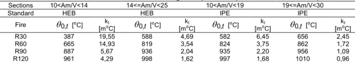
The new proposal is based on the same formulae of Eurocode 4 (Eq. 4), but using a bilinear approximation for temperature, using a new empirical coefficient kt and a new reference value
t
, 0
, see table 4.
Table 4 – Parameters to determine flange temperature (Section HEB and IPE).
Sections 10<Am/V<14 14<=Am/V<25 10<Am/V<19 19<=Am/V<30
Standard HEB HEB IPE IPE
Fire 0,t [⁰C] [mk⁰t C] 0,t [⁰C] [mk⁰t C] 0,t [⁰C] [mk⁰t C] 0,t [⁰C] [mk⁰tC]
R30 387 19,55 588 4,69 582 6,45 656 2,45
R60 665 14,93 819 3,54 824 3,75 862 1,72
R90 887 5,67 936 2,04 935 2,20 956 1,09
R120 961 4,29 998 1,62 997 1,68 1010 0,96
The effect of fire on the web of the cross section was determined by the 400 °C isothermal criterion. This procedure defines the affected zone of the web and predict the web reduction height, see Figure 4. The numerical results demonstrate a strong dependence on the section factor, regardless of the fire resistance class, unlike the simplified method of EN1994-1-2. The results of EN1994-1-2 are unsafe for all fire resistance classes and for all section factors. The new proposal presents a parametric expression that depends on section factor and standard fire resistance class, Eqs. (9-10). Both equations have the application limits defined in table 5.
Paulo Piloto, David Almeida, A.B Ramos-Gavilán and Luís M.R. Mesquita
35
0.03
/2 (, )0035 . 0 100 /
2hw,fi hi t2 Am V t2.02 Am V HEB (9)
0.03
(, )002 . 0 100 /
2hw,fi hi t2 Am V t1.933 Am V IPE (10)
Table 5 – Application limits for HEB and IPE cross sections.
Standard fire resistance Section factor (HEB) Section factor (IPE)
R30 Am/V <22.22 Am/V <30.00
R60 Am/V <15.38 Am/V <18.56
R90 Am/V <12.22 Am/V <14.97
R120 Am/V <11.11 -
The arithmetic average temperature w,tof the effective web section was defined by the nodes
under the limiting condition and plotted in Figure 5 (ANSYS). Temperature results of EN1994-1-2 were determined by the inverse method, using the reduction factor of the yielding stress
) ( 16 . 0
1 Ht h . The new proposal was adjusted to numerical results.
Figure 5 – Average web temperature. HEB sections (left). IPE Sections (right).
The numerical result of the third component was determined by the 500 ºC isothermal. The external layer of concrete to be neglected was measured in both principal directions, defining
vertical fi c
b, , and bc,fi,horizontal. According to EN1994-1-2 [1], the thickness of concrete to be
neglected depends on section factor for standard fire resistance of R90 and R120. The numerical results demonstrates a strong dependence on section factors for all standard fire resistance classes. Figure 6 presents the new proposal for bc,fi,verticaland bc,fi,horizontal for HEB
sections. Similar results were obtained to IPE sections. Tables 6-7 provide the new formulae to determine the thickness of concrete to be neglected in fire design.
Paulo Piloto, David Almeida, A.B Ramos-Gavilán and Luís M.R. Mesquita
36
Table 6 - Thickness reduction of the concrete in sections HEB.
A V
b
A V
ca
bc,fi m 2 m
horizontal fi
c
b, , bc,fi,vertical
Standard Fire a b c a b c Section factor
R30 0,0000 0,0809 13,5 0,000 0,372 3,5 10<=Am/V<=25
R60 0,1825 -4,2903 50,0 0,1624 -3,2923 41,0 10<=Am/V<=20
R90 1,0052 -22,575 163,5 1,8649 -43,287 298,0 10<=Am/V<=17
R120 0,0000 7,5529 -35,5 0,000 6,0049 9,0 10<=Am/V<=13
Table 7 - Thickness reduction of the concrete in sections IPE.
A V
b
A V
ca
bc,fi m 2 m
horizontal fi
c
b, , bc,fi,vertical
Standard Fire a b c a b c Section factor
R30 0,0000 0,2206 10,5 0,0000 0,9383 -3,0 14<=Am/V<=30
R60 0,2984 -8,8924 93,0 0,5888 -15,116 135,0 14<=Am/V<=22
R90 1,3897 -38,972 313,0 2,0403 -50,693 393,0 14<=Am/V<=17
R120 0,0000 18,283 -199,0 0,0000 48,59 -537,0 14<=Am/V<=15
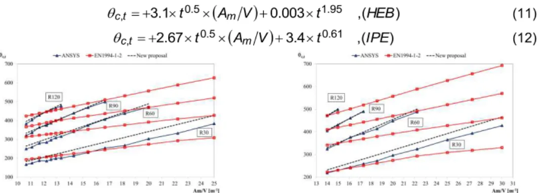
The average temperature of the residual concrete section is represented in Figure 7. The new proposal introduces a parametric approximation, based on the standard fire resistance and section factor, Eqs. 11-12.
0.003 (, )1 .
3 0.5 1.95
,t t Am V t HEB
c
(11)
3.4 (, )67 .
2 0.5 0.61
,t t Am V t IPE
c
(12)
Figure 7- Average temperature of residual concrete. HEB sections (left). IPE Sections (right).
Paulo Piloto, David Almeida, A.B Ramos-Gavilán and Luís M.R. Mesquita
37
7.5 0.1 8 390 ,( )1 .
0 1.1 1.765
,t t Am V t t u HEB
s
(13)
11.0 0.1 8 115 ,( )0 .
14 1.795
,t Am V t t u IPE
s
(14)
Figure 8 – Average temperature of rebars. HEB sections (left). IPE Sections (right).
5. FIRE RESISTANCE ACCORDING TO NEW PROPOSAL
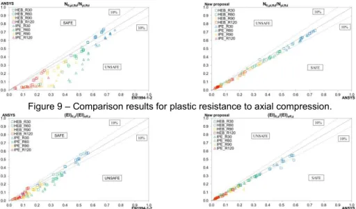
Figures 9-10 present the margin of safety of the new proposal for the plastic resistance to axial compression and the effective flexural stiffness around the weak axis.
Figure 9 – Comparison results for plastic resistance to axial compression.
Paulo Piloto, David Almeida, A.B Ramos-Gavilán and Luís M.R. Mesquita
38
6. CONCLUSIONS
The simplified method proposed in Annex EN1994-1-2 G is unsafe for certain classes of fire resistance compared to numerical results. This paper presented new formulae, with safety guarantee to the calculation of plastic resistance to axial compression and effective flexural stiffness of the cross-section in fire conditions.
7. REFERENCES
[1] CEN - EN 1994-1-2; “Eurocode 4 - Design of composite steel and concrete structures- Part 1-2: General rules - Structural fire design”; Brussels, August 2005.
[2] ISO 834-1. “Fire-resistance tests - Elements of building construction – Part 1: general requirements”. 1999.
[3] CEN - EN 1991-1-2; “Eurocode 1: Actions on structures - Part 1-2: General actions - Actions on structures exposed to fire”; Brussels, November 2002.
[4] CEN - EN 1993-1-2. Eurocode 3: Design of steel structures - Part 1-2: General rules - Structural fire design. Brussels, April 2005.
[5] CEN - EN 1992-1-2. Eurocode 2: Design of concrete structures - Part 1-2: General rules - Structural fire design. Brussels, December 2004.
![Table 3 – Reduction factors k and y, t k for reinforcement. E, t tky, k y, t k y, t k y, t k E, t k E, t k E, t k E, t u [mm] R30 R60 R90 R120 R30 R60 R90 R120 40 1,000 0,789 0,314 0,170 0,830 0,604 0,193 0,110 45 1,000 0,883 0,43](https://thumb-eu.123doks.com/thumbv2/123dok_br/16983811.763121/7.748.103.649.741.836/table-reduction-factors-reinforcement-e-tky-e-e.webp)