SURFACE COLLISION DETECTION FOR VIRTUAL
PROTOTYPING
Mauro Figueiredo
Universidade do AlgarveABSTRACT
This paper presents an efficient collision detection algorithm designed to support assembly and maintenance simulation of complex assemblies. This approach exploits the surface knowledge, available from CAD models, to determine intersecting surfaces. It proposes a novel combination of Overlapping Axis-Aligned Bounding Box (OAABB) and R-tree structures to gain considerable performance improvements. This paper also shows an efficient traversal algorithm based on the R-tree structure of Axis-Aligned Bounding Boxes to determine intersecting objects and intersecting surfaces between three-dimensional components, for supporting the recognition of constraints in assembly and disassembly operations in virtual prototyping environments.
The implementation of the proposed collision detection algorithm performs well against moderately complex industrial case studies. Current experimental results show that this implementation is effective in determining intersecting surfaces at interactive rates with moderately complex real case studies.
KEYWORDS
Collision detection, virtual prototyping, bounding volume hierarchies.
1. INTRODUCTION
An assembly constraint-based approach is used for simulating physical realism and interactivity for assembly and disassembly operations in virtual prototyping environments (Murray and Fernando 2003). It relies on a set of geometric constraint relationships that are automatically established or removed as the user manipulates the assembly components. The functional modules used in this approach are collision detection, constraint recognition, constraint satisfaction, constraint management and constraint motion. The automatic constraint recognition process uses collision detection services for various purposes such as (a) to provide collision response to stop object penetration, (b) to identify colliding surfaces to support the recognition of assembly relationships between the assembly parts, (c) to simulate constrained motion, (e) to simulate kinematics motion and sliding, thus assisting users to carry out precise object manipulations.
Real-time recognition of assembly constraints demands an efficient surface-based collision detection algorithm. Virtual prototyping models, generated by Computer-Aided Design (CAD) systems, are surface-based. The recognition of constraints for assembly and disassembly operations relies on the knowledge of the intersecting surfaces. However, current collision detection algorithms for virtual environments are based on polygonal models and determine intersecting polygons, disregarding all the surface data of the CAD model. While these toolkits are useful for supporting physically-based simulation of rigid objects, they do not support the extra functionalities necessary for supporting assembly simulation, based on an assembly constraint-based approach. The awareness of all the colliding surfaces is valuable information to allow the automatic recognition of assembly constraints between surfaces.
This paper presents the implementation of a collision detection approach for the narrow phase. It determines intersecting surfaces between three-dimensional components, for supporting the recognition of constraints in assembly and disassembly operations in virtual prototyping environments.
The approach presented uses Axis-Aligned Bounding Boxes (AABBs), the Overlapping Axis-Aligned Bounding Box (OAABB) concept and a hierarchy of R-trees to improve performance of the collision detection process.
The OAABB volume was introduced in (Figueiredo et al. 1993) for improving performance in the determination of intersecting polygons. Smith et al. 1995 use the same concept but with an octree data structure for finding intersecting polygons. This paper presents new work that extends the OAABB concept for surfaces. This paper also shows the novel combination of OAABB at three different levels: objects, surfaces and triangles. The OAABB is used to reduce: (i) the number of axis-aligned bounding boxes intersections and (ii) the number of bounding volume update operations.
This paper also presents new work using R-trees in the narrow phase for speeding up the collision detection problem. Held et al. 1995 implemented a collision detection approach to find collisions of only one moving object in a virtual environment. They use a binary R-tree to represent the static scenario. The approach presented is also novel work with R-trees. It allows any number of moving objects. A novel structure is described where each object is represented by an R-tree data structure at two-levels. First, for each object, an R-tree of surfaces is built, grouping neighboring surfaces. Secondly, the set of triangles that represent each surface is organized in another R-tree structure. The detailed design of an efficient R-tree structure for the collision detection is presented. It is also described a novel traversal algorithm for collision detection that takes advantage of this 3D geometry structure.
Together, the OAABB and the R-tree structures, enables the effective reduction of the number of intersection operations, hence providing considerable performance gains. Results show that the proposed collision detection achieves interactive rates in real industrial applications as desired.
The paper is organized as follows. Section 2 presents related collision detection approaches for the determination of intersecting triangles between two objects. Section 3 presents the key factors and the implementation of the collision detection algorithm to compute intersecting surfaces between three-dimensional objects. Section 4 presents the evaluation results. Conclusions are presented in section 5.
2. BACKGROUND
Bounding volume hierarchies (BVH) are frequently used to organize the triangles of an object to improve the performance of the collision detection process, by reducing the number of pairs of bounding volume tests. The classic scheme for hierarchical collision detection is a simultaneous recursive traversal of two bounding volumes trees A and B.
Several types of bounding volumes are available. Bounding spheres can be used (Bradshaw and Sullivan 2004). SOLID (Van Der Bergen 1997) and OPCODE (Terdiman 2001) uses axis-aligned bounding boxes (AABB). RAPID (Gottschalk et al. 1996), V-COLLIDE (Hudson,et al. 1997), PQP (Larsen, et al. 1999), H-COLLIDE (Gregory, et al. 1999), use oriented bounding boxes (OBB). QuickCD (Klosowski, et al. 1998) and Dop-Tree (Zachmann. 1998) uses k-dops; and Swift++ (Ehmann and Lin 2001) uses convex hulls (CH). There are also hybrid approaches like QuOSPOs (He 1999) that use a combination of OBBs and k-dops.
It is very difficult to compare different approaches since performance also depends on the shapes of the models, type of contact, size of the models and others.
Bounding spheres main advantage is that they are faster to intersect and update. The main disadvantage is that they do not approximate objects tightly.
The main advantage of SOLID, OPCODE and Box-Tree is that AABBs are faster to intersect. When using AABBs, only six comparisons are required to find out if two axis-aligned bounding boxes are overlapping. It is also possible to say that two AABBs are disjoint, in the best case situation, with only one comparison. Another advantage of using AABBs is that it is simple to update these volumes as an object rotates and translates.
RAPID approximates 3D objects with hierarchies of oriented bounding boxes (OBBs). An OBB is a rectangular bounding box with an arbitrary orientation so that it encloses the underlying geometry more tightly. The representation of an oriented bounding box encodes position, widths and orientation.The main advantage of RAPID is that OBBs are better approximations to triangles reducing effectively the number of intersecting operations.
V-COLLIDE solves the broad-phase of the collision detection using a sweep-and-prune operation to find pairs of objects potentially in contact. It uses RAPID to find in the narrow phase which pairs of objects intersect.
PQP solves the narrow phase and is also based on the RAPID library. It uses oriented bounding boxes to find intersecting objects. PQP also computes the distance between closest pair of points using swept spheres. H-COLLIDE is a framework to find collisions for haptic interactions. It uses a hybrid hierarchy of uniform grids and trees of OBBs to exploit frame-to-frame coherence. It was specialized to find collisions between a point probe against 3D objects.
The QuickCD and Dop-Tree implementations build a hierarchy tree of discrete orientation polytopes. Discrete orientation polytopes, or k-dops, are convex bounding volumes whose faces are determined by halfspaces whose outward normals come from a small fixed set of k orientations. The main advantage of using discrete orientation polytopes is that k-dops are better approximations to the underlying geometry than AABBs with the advantage of its low cost compared to OBBs. A major drawback of QuickCD is that allows only one moving object.
Swift++ builds a hierarchy of convex hulls and intersection is tested using a modified Lin-Canny (Lin and Canny 1991) closest feature algorithm.
He (1999) uses a hybrid approach that combines OBBs and k-dops called QuOSPOs. This approach provides a tight approximation of the original model at each level.
Since collision detection is a very demanding task, researchers are also working in using existing graphics accelerated boards (GPU) (Baciu and Wong 2003, Knott and Pai 2003, Govindaraju et al. 2003, Yoon et al. 2004) or dedicated hardware (Raabe et al. 2006) to accelerate collision detection by hardware.
Algorithms using graphics hardware use depth and stencil buffer techniques to determine collisions between convex (Baciu and Wong 2003) and non-convex (Knott and Pai 2003) objects. CULLIDE (Govindaraju et al. 2003) is also a GPU based algorithm that uses image-space occlusion queries and OBBs in a hybrid approach to determine intersections between general models with thousands of polygons. MRC (Yoon et al. 2004) deals with large models composed of dozens of millions of polygons by using the representation of a clustered hierarchy of progressive meshes (CHPM) as a LOD hierarchy for a conservative errorbound collision and as a BVH for a GPU-based collision culling algorithm.
These GPU-based algorithms are applicable to both rigid and deformable models since all the computations are made in the image-space. Collision detection methods using GPUs have the disadvantage that they compete with the rendering process, slowing down the overall frame rate. Furthermore, some of these approaches are pure image based reducing their accuracy due to the discrete geometry representation.
Collision detection with dedicated hardware acceleration techniques for k-dops bounding volumes has been experimented (Raabe et al. 2006). An ASIC and a FPGA collision detection single-chip was developed with two main stages, one for traversing simultaneously a hierarchy of k-dops and one for intersecting triangles. The ASIC and the FPGA implementations are up to 1000 and four times, respectively, faster than the software intersection tests on a standard CPU.
3. COLLISION DETECTION ALGORITHM
3.1 Design Choices
In this research, a 3D object is defined by a collection of surfaces in the three-dimensional space. Each surface is tessellated individually and represented as a collection of triangles.
The time to determine collisions between two objects using BVH depends on: (1) the cost of intersecting and updating bounding volumes; (2) the cost of intersecting triangles; and (3) on the number of such operations.
The choice of bounding volume type influences performance of the collision detection process. The implementation of the collision detection algorithm presented in this paper uses axis aligned bounding boxes for four reasons: i) they are fast to intersect; ii) use less memory; iii) hierarchies of AABBs are faster to build; and iv) faster to update, when compared to oriented bounding boxes and discrete orientation polytopes. It was decided to use R-trees (Guttman 1984) to build the bounding volume hierarchies and organize the 3D geometry of objects for improving the performance of the collision detection process. Some important properties of the R-tree can be underlined here that contributed to its choice: 1) At any level of the tree, each primitive is associated with only a single node; 2) In an R-tree all leaf nodes appear on the same level; 3) The
depth of a R-tree storing n primitives is logmn, m is the minimum number of children of a node; 4) The total
number of primitives stored in a R-tree equals the number of original primitives.
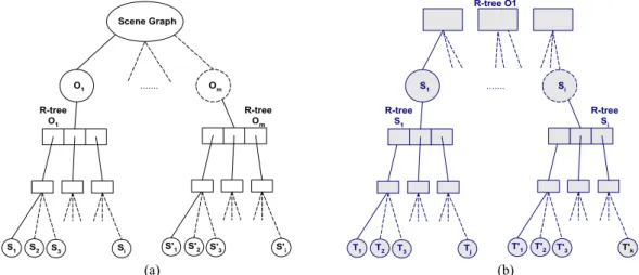
For the implementation of the collision detection algorithm each object is represented by an R-tree data structure in its own local coordinate system (Figure 1-a). A hierarchical tree is built, grouping neighboring surfaces. The leaf nodes of the R-tree point to the geometry of the surfaces that define the object. For two objects, it checks for collisions between surfaces which are in the neighborhood, eliminating comparisons with those which are far away.
The same idea is applied for surfaces. Surfaces from a three-dimensional model can be complex with a large number of triangles. An R-tree can be used to organize the triangles spatially and hence to quickly reject triangles that cannot intersect (Figure 1-b). In this approach, an R-tree is computed for each surface, grouping neighboring triangles to eliminate comparisons with those that are faraway from the area of intersection. S1 S2 S3 Scene Graph O1 ... Om Si R-tree O1 S'1 S'2 S'3 S'i R-tree Om T1 T2 T3 R-tree O1 S1 ... Si Tj R-tree S1 T'1 T'2 T'3 T'k R-tree Si (a) (b)
Figure 1. (a) Each object of the scene graph is represented by its own R-tree data structure representing its surfaces. (b) Each surface of the 3D model is also represented by its own R-tree data structure.
The proposed algorithm is based in the use of the Overlapping Axis-Aligned Bounding Box, OAABB (A,
B), of two geometric primitives, to improve the performance of the collision detection process. Figueiredo et al. (1993) introduced this concept for improving performance in the determination of intersecting polygons.
Smith et al. (1995) also use the same concept together with an octree data structure for finding intersecting polygons. The implementation described in this paper extends the OAABB concept for surfaces.
The OAABB is defined as the volume that is common to two axis-aligned bounding boxes of A and B,
AABB(A) and AABB(B), aligned with the coordinate axes. The OAABB is used to filter out primitives that
cannot intersect.
3.2 Implementation
This section presents the algorithm for determining intersecting surfaces between a pair of 3D objects. This paper presents the latest development of some of the initial ideas presented earlier in (Figueiredo and Fernando 2003) and (Figueiredo and Fernando 2004) and it is the result of the gathered experience obtained with real industrial case studies. It also describes a novel implementation of the traversal algorithm for collision detection that takes advantage of the R-Trees structure.
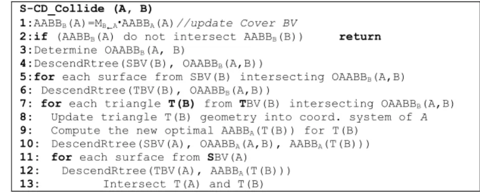
The algorithm to find intersecting surfaces is presented in Figure 2.
The collision detection algorithm, described in the following paragraphs, takes advantage of the scene graph structure built from 3D data models. In this approach, each 3D model is defined as a collection of surfaces. Each surface is tessellated individually and represented as a collection of triangles.
The collision detection process first checks if objects A and B are disjoint (line 1-2 in Figure 2). The bounding volumes of each object are originally computed in the object’s local coordinate system, AABBA(A)
and AABBB(B), respectively. The transformation matrix that converts the local representation of object A into
the coordinate system of object B, by computing the cover axis-aligned bounding box, AABBB(A). Once the
bounding volumes of each object are in the same coordinate system they can be checked for overlap. If this pair of AABBs does not overlap, then the corresponding two objects are not intersecting and the process ends. If they overlap, then the system determines the Overlapping Axis-Aligned Bounding Box,
OAABBB(A,B) of the two objects (line 3 in Figure 2), which is defined in the local coordinate system of object
B.
S-CD_Collide (A, B)
1:AABBB(A)=MB AAABBA(A)//update Cover BV
2:if (AABBB(A) do not intersect AABBB(B)) return
3:Determine OAABBB(A, B)
4:DescendRtree(SBV(B), OAABBB(A,B))
5:for each surface from SBV(B) intersecting OAABBB(A,B)
6: DescendRtree(TBV(B), OAABBB(A,B))
7: for each triangle T(B) from TBV(B) intersecting OAABBB(A,B)
8: Update triangle T(B) geometry into coord. system of A
9: Compute the new optimal AABBA(T(B)) for T(B)
10: DescendRtree(SBV(A), OAABBA(A,B), AABBA(T(B)))
11: for each surface from SBV(A)
12: DescendRtree(TBV(A), AABBA(T(B)))
13: Intersect T(A) and T(B)
Figure 2. Pseudo-code for finding intersecting surfaces.
The next step of the collision detection process determines the surfaces from object B intersecting the OAABB (line 4 of Figure 2). As mentioned before, the surfaces of object B are organized in a Surface Bounding Volume R-tree called SBV(B). The surfaces of B are stored at the leaf nodes of the SBV(B) R-tree. By descending this R-tree, the surfaces of object B that do not intersect the OAABBB(A,B) are filtered out.
Only the surfaces at the leaf nodes intesecting the OAABBB(A,B) are candidate for collision.
Each surface of object B is tessellated and represented by a collection of triangles. The triangles of each surfaces are also represented in its own Triangle Bounding Volume R-tree data structure, organizing its triangles into sub-regions. The next step of the collision detection process descends to the Triangle Bounding Volume R-tree TBV(B) of each candidate surface from object B (lines 5 and 6 of Figure 2). This stage determines the triangles of object B intersecting the OAABB.
Using the OAABB, the collision detection manager filters out surfaces and triangles of object B that cannot intersect.
The triangles of object B intersecting the OAABB are transformed into the coordinate system of object A (line 8). At this point is also determined the triangle’s optimal bounding volume (line 9). The new optimal AABB is built by computing the new minimal and maximal values in the x, y and z axes, defining the new extents of the bounding volume. This stage computes the optimal bounding volume, since it is faster than computing the cover AABB. Furthermore, the optimal AABB encloses the triangle better than a cover AABB.
Then, the collision detection process descends the Surface Bounding Volume SBV(A) R-tree for object A (line 10 of Figure 2). In this step it finds surfaces of object A intersecting the OAABB and the triangle’s optimal AABBA(T(B)) of object B.
To determine if a pair of surfaces intersects, it is necessary to find a pair of intersecting triangles. Then, the collision detection process descends to the Triangle Bounding Volume R-tree TBV(A) of each candidate surface from object A (lines 11 and 12 of Figure 2). This stage determines the triangles of object A who’s bounding volumes intersect the triangle’s optimal AABB of object B.
The final step is to proceed with the intersection between pairs of candidate triangles (line 13) implemented with Guige and Devillers (2003) algorithm. If there is a pair of intersecting triangles then the corresponding surfaces is intersecting.
4. EXPERIMENTAL RESULTS
This section presents the performance evaluation results of the novel collision detection algorithm described in this paper.
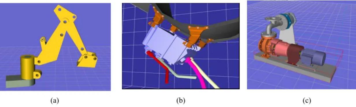
Three examples that represent user operations to assembly the components of the described models are used. Case study 1 (Figure 3-a) is the assembly process to build a digger mechanism from D-cubed Ltd. Case study 2 (Figure 3-b), from the Sener Company in Spain, is the building process of an electronic control box from an aircraft engine. Case study 3 (Figure 3-c), from UMIST in Manchester, is the assembly of a process plant. These test scenarios are real case applications from maintenance simulation in virtual prototyping environments. For example, case study 2 from SENER Company in Spain, is part of a real product development from the aerospace domain, where SENER was responsible for designing connectors, tubing, wire harnesses, brackets, clips, and accessories for an aircraft engine electronic control box. It reflects the real scenario and the working environment, including the complexity of the model and the realism of the activities. The real working requirement on which the test case is based on was to demonstrate to the customer that the electronic control box from an aircraft engine can be removed and replaced from the airframe in less than 60 minutes following the instructions defined in the standard maintenance handbook.
Table 1 shows the complexity of the digger, sener and process plant environments. The most complex case scenario, in terms of number of objects in the scene, is the sener model with 25 objects (parts). The sener and process plant have about the same complexity when related to the number of surfaces and the total number of triangles in the scene. The process plant has a lower number of objects in the scene than the sener model. The digger model has a lower number of surfaces and triangles. Table 1 also presents the total number of intersecting steps for the assembly operations for each case study.
All the experiments run in an Intel Core 2 Duo T7300, 2GByte of RAM memory at 2GHz.
(a) (b) (c)
Figure 3. Test case scenarios: (a) Digger model; (b) Sener Model and (c) Process plant. Table 1. Complexity of the models used in test case scenarios.
Test Case Scenario Digger Sener Process Plant
Number of Objects 5 25 8
Total Number Surfaces Scenario 109 1 250 1 073 Total Number Triangles Scenario 2 452 25 525 24 415 Number of intersecting steps for the entire assembly simulation 507 980 233
The collision detection implementation can be configured to determine first intersecting surface, all intersecting surfaces or all the intersecting triangles between three-dimensional components in a virtual prototyping environment. Table 2 presents these times. The proposed collision detection algorithm achieves interactive rates in real industrial applications as desired.
It is also important to compare the performance of this algorithm with other collision detection toolkits. Tables 3 and 4 present the times obtained comparing the implementation described in this paper, named as S--CD (Surface Collision Detection), with PQP, RAPID, OPCODE and Dop Tree. The times presented were obtained in the determination of the first intersecting triangle (Table 3) and also for all the intersecting triangles (Table 4). S-CD is effective in the determination of intersections interactively.
Table 5 presents the time obtained when the overlapping axis-aligned bounding box (OAABB) approach is not used. This table presents the time to find first, all intersecting surfaces and all intersecting triangles.
Tables 2 and 5 show there is an improvement in performance by using the overlapping axis aligned bounding box.
This improvement is explained by table 6. The cost of finding collisions depends on several factors. The choice of type of bounding volume influences the number and the cost of executing bounding volume
intersections. For AABBs and k-dops the cost and the number of updating bounding volumes also influences performance. Table 6 shows an effective reduction in the number of AABBs tests and update bounding volume operations explaining the better performance obtained by the OAABBs.
Table 2. Collision detection time to find intersecting surfaces.
Time in milliseconds per step to determine: Digger Sener Process Plant (i) first intersecting surface per step 0.04 0.15 0.09 (ii) all intersecting surfaces 0.25 0.55 0.94 (iii) all intersecting surfaces and all intersecting triangles 0.36 0.72 1.26
Table 3. Time to find first triangle intersection.
Time to find first triangle intersection (milliseconds) Digger Sener Process Plant
PQP 0.42 0.32 0.40
RAPID 0.06 0.10 0.12
OPCODE 0.02 0.08 0.04
Dop Tree 0.77 1.25 1.52
S-CD 0.04 0.15 0.09
Table 4. Time to find all triangle intersections.
Time to find all triangle intersections (milliseconds) Digger Sener Process Plant
PQP 1.82 1.57 4.96
RAPID 1.24 1.18 3.62
Dop Tree 5.81 10.48 17.29
OPCODE 0.90 1.73 2.09
S-CD 0.36 0.72 1.26
Table 5. Collision detection time to find intersecting surfaces (without using OAABB).
Time in milliseconds per step to determine: Digger Sener Process Plant (i) first intersecting surface per step 0.09 0.38 0.28
(ii) all intersecting surfaces 0.34 1.06 1.75
(iii) all intersecting surfaces and all intersecting triangles 0.50 1.23 2.06
Table 6. Average number of operations per step to determine first intersecting surface.
Number of operations: Digger Sener Process Plant
Using OAABB Yes No Yes No Yes No
AABBs tests 507 754 2256 3942 1263 2915
AABBs updates 39 202 87 825 102 713
5. CONCLUSION
This paper presents a novel collision detection algorithm for supporting assembly and maintenance simulations in virtual prototyping environments which is publicly available at http://w3.ualg.pt/~mfiguei. It determines intersecting surfaces between three dimensional components at interactive rates.
To improve performance, the collision detection uses the overlapping axis-aligned bounding box approach (OAABB), axis-aligned bounding boxes (AABBs) and the R-tree structure. The OAABB approach is used effectively together with the two level hierarchy of R-tree structure to reduce the number of updates and checks between bounding volumes, taking the effective advantage of the low cost of intersecting AABBs. It is also described a novel traversal algorithm that takes effective advantage of the two-level R-tree structure. The use of OAABBs also allows the significant reduction of the number of bounding volume intersections and updates.
The approach presented in this paper was tested with three industrial maintenance scenarios of moderate complexity that were used to test assembly operations, running in an Intel Core 2 Duo T7300 at 2GHz. The proposed approach determines intersecting surfaces interactively and effectively addressed the assembly operations carried on.
REFERENCES
Baciu, G. and Wong, S., 2003. Image-based Techniques in a Hybrid Collision Detector. IEEE Trans. On Visualization and Computer Graphic, 9, 2, 254-271.
Bradshaw, G. and O’Sullivan, C., 2004. Adaptive medial-axis aproximation for sphere-tree construction. ACM Transactions on Graphics, 23, 1–26.
Ehmann, S. and Lin, M., 2001. Accurate and fast proximity queries between polyhedra using convex surface decomposition. Computer Graphics Forum. 20, 500–10.
Figueiredo, M. and Fernando, T., 2003. An Unified Framework to Solve the Broad and Narrow Phases of the Collision Detection Problem in Virtual Prototype Environments. Proc. of International Conference on Geometric Modelling and Graphics, 130-136.
Figueiredo, M. and Fernando, T., 2004. An Efficient Parallel Collision Detection Algorithm for Virtual Prototype Environments. Proc. of the Tenth International Conference on Parallel and Distributed Systems, 249-256.
Figueiredo, M., Boehm, K. and Teixeira, J., 1993. Precise Object Interactions using Solid Modeling Techniques. Proc. of IFIP TC 5/WG 5.10 Conference on Modeling in Computer Graphics, 157-176.
Gottschalk, S. , Lin, M. and Manocha, D., 1996. Obb-tree: A hierarchical structure for rapid interference detection. Proc. of ACM Siggraph'96, 171-180.
Govindaraju, N., Redon, S., Lin, M. and Manocha, D., 2003. CULLIDE: Interactive collision detection between complex models in large environments using graphics hardware. Graphics Hardware 2003, 25–32.
Gregory, A., Lin, M., Gottschalk, S. and Taylor, R., 1999. A Framework for Fast and Accurate Collision Detection for Haptic Interaction. Proc. of IEEE Virtual Reality Conference, 38-45.
Guige, P. and Devillers, O., 2003. Fast and Robust Triangle-Triangle Overlap Test using Orientation Predicates. Journal of Graphics Tools, 8, 1, 25-42.
Guttman A., 1984. R-trees: A dynamic index structure for spatial searching. Proc. of the ACM SIGMOD International Conference On Management of Data, 47-57.
He, T., 1999. Fast collision detection using QuOSPO trees. Proc. of the Symposium on Interactive 3D graphics, 55–62. Held, M., Klosowski, J. and Mitchell, J. 1995. Evaluation of Collision Detection Methods for Virtual Reality
Fly-Throughs. Proc. Seventh Canadian Conference Computer Geometry, 3, 205-210.
Hudson, T., Lin, M., Cohen, J., Gottschalk, S. and Manocha, D., 1997. VCollide: Accelerated Collision Detection for VRML. Proc. of VRML.
Klosowski, J., Held, M., Mitchell, J., Sowizral, H. and Zika, K., 1998. Efficient Collision Detection using Bounding Volume Hierarchies of k-DOPs. IEEE Trans. On Visualization and Computer Graphics 4, 1, 21-36.
Knott, D. and Pai, D., 2003. ClnDeR: Collision and Interference Detection in Real-time using Graphics Hardware. Proc. of Graphics Interface 2003, 73-80.
Larsen, E., Gottschalk, S., Lin, M. and Manocha, D. 1999. Fast Proximity Queries with Swept Sphere Volumes. Technical report TR99-018, UNC.
Lin, M. and Canny, J. 1991. Efficient algorithms for incremental distance computation. IEEE Conference on Robotics and Automation, 1008–1014.
Murray, N., and Fernando, T. 2003. Development of an Immersive Assembly and Maintenance Environment. In Proc. Advanced Research in Virtual and Rapid Prototyping(VRAP 2003), Leiria, pp. 341-348
Raabe, A., Hochgurtel, S., Anlauf J. and Zachmann, G., 2006. Space-efficient FPGA-accelerated collision detection for virtual prototyping. Proc. of Design, Automation and Test in Europe, 206-211.
Smith, A., Kitamura, Y., Takemura, H. and Kishino, F., 1995. A simple and efficient method for accurate collision detection among deformable objects in arbitrary motion. Proc. of the IEEE Virtual Reality Annual Symposium, 136-145, 1995.
Terdiman, P., 2001. Memory-optimized bounding-volume hierarchies. http://www.codecorner.com/Opcode.pdf.
Van Der Bergen, G., 1997. Efficient Collision Detection of Complex Deformable Models using AABB Trees. Journal of Graphics Tools 2, 4, 1-13.
Yoon, S., Salomon, B., Lin, M. and Manocha, D., 2004. Fast Collision Detection between Massive Models using Dynamic Simplification. Eurographics Symposium on Geometry Processing, 136-146.
Zachmann, G., 1998. Rapid Collision Detection by Dynamically Aligned DOP-Trees. In Proc. of IEEE Virtual Reality Annual International Symposium; VRAIS ’98, pages 90–97. Atlanta, Georgia.