C. H. Ahrens
Universidade Federal de Santa Catarina Departamento de Engenharia Mecânica CIMJECT 88040-900 Florianópolis, SC. Brazil [email protected]
A. S. Ribeiro Jr
Universidade Federal de Santa Catarina Departamento de Engenharia Mecânica CIMJECT 88040-900 Florianópolis, SC. Brazil [email protected]
V. E. Beal
Universidade Federal de Santa Catarina Departamento de Engenharia Mecânica CIMJECT 88040-900 Florianópolis, SC. Brazil [email protected]
Heat Flux Canals (HFC) Technique:
An Alternative to Cool Down
Stereolithography Moulds
The design of injection mould inserts obtained by stereolithography (SL) has various recommendations that are based on experimental work done by researchers over the last decade. There are no final conclusions about the best cooling technique for SL inserts. Moreover, no criteria are presented concerning structural and thermal designs based on stress-strain analysis, although a number of researchers consider ejection forces as the main failure effect of the SL tool. This work presents an alternative technique to cool down SL inserts, based on heat flux canals that are strategically positioned on hot areas along the cavity walls. Using this approach it is possible to keep direct contact between the back metal filling of the stereolithography insert and the injected thermoplastic material. This paper shows the results of aspects such as thermal evaluation in a FEM analysis, where the heat flux canals, solid SL moulds and the traditional Direct AIM™ process performances have been compared. The results indicate that this evolution of the Direct AIM™ process may improve the average life of SL inserts while keeping the traditional one-week development for the tool.
Keywords: Rapid tooling, stereolithography, injection moulding, finite element analysis
Introduction
The use of stereolithography moulds to produce injection-moulded parts has achieved great eminence in the rapid development of products. The production of parts using this technique shows advantages, over other Rapid Tooling technologies such as good surface quality, close tolerances and short time to obtain pre-series. Nevertheless, this technique has limitations about the quantity of parts that can be moulded. Depending on geometric complexity, it is possible to obtain over 500 quality parts before the
mould fails (Dickens, 1999). 1
The early failure of SL moulds is mainly caused by a decrease of the SL resin mechanical strength, when the mould temperatures increase. It causes fractures at the highest stress regions of the mould during the part ejection. Various researchers point out this phenomenon as the main effect of the SL tool’s life reduction (Cedorge et al., 1999; Gomide, 2000; Hopkinson et al., 2000).
In this work a new technique to improve the heat transfer from
SL moulds using heat flux canals (HFC) is proposed and evaluated
numerically. If correctly used, this new technique may increase the
quantity of parts that can be made using SL moulds by reducing the exposure time of the SL resin to the high temperatures during the injection moulding process.
Stereolithography Moulds Background
The premature failure of SL moulds has been the subject of many studies. Authors as Jacobs (1996) and Hopkinson & Dickens (2000) affirm that the rupture of this kind of tool usually occurs due to the friction between the moulded part and the mould surfaces during the part ejection. Much research to evaluate the ejection forces and to reduce their effects over SL moulds has been performed by these and other authors. Hopkinson & Dickens (2000) for example, suggested a procedure to predict ejection forces in SL moulds. Also, Cedorge et al (1999) presented guidelines to use SL moulds based on results obtained in a series of experimental studies.
An important aspect about the use of SL moulds is the effect of the temperature on the SL resins mechanical properties. As shown in
Fig. 1 the Ultimate Tensile Stress (UTS) of the Ciba SL 5170 resin
decreases significantly when the temperature is increased (Hopkinson & Dickens, 2000). Authors have evaluated the use of alternatives cooling techniques to minimize this effect (Yun Li et al, 2000). The objective of these researches is to reduce the SL resin exposure to the high injection moulding temperature to increase the mould life expectance.
Figure 1. Mechanical behavior of the SL resin 5170 (adapted from Hopkinson & Dickens, 2000).
circuit to help the cooling of the SL cavity. Figure 2 presents an illustrative sketch of the SL moulds using these techniques.
#1 - Shell Mould #2 - Solid Mould #3 - Conformal Cooling Mould
water
molded part
core
cavity
copper pipe SL shells back material
core
cavity molded part solid SL mould halves water
core
cavity molded part solid SL mould halves
conformal water canal
Figure 2. Three different types of SL moulds cooling systems.
The authors that have been using SL moulds affirm that the shell moulds do not significantly improve the heat transfer (Yun Li et al, 2000), moreover the back filling process may cause geometric distortions in the cavity. It is pointed out that the thermal diffusivity of the SL resins is too low to transfer heat from the part to the back filling material through the shell (Example: DSM 7110 Thermal Conductivity, k = 0.19 W/m*K). This is easy to show through thermal conductivity equations or thermal FEA (Finite Element Analysis). A FEA analysis of the SL mould was performed and the results were compared with the experimental results of the temperature obtained in the shell mould from a case study performed by Gomide (2000). The temperature range of the back filling material had presented few changes during the injection mould cycle in both, the experimental and the FEA results. This suggests that the heat is more efficiently extracted from the moulds surface, using an air jet cooling as usually done by users and researchers of SL moulds.
Hopkinson & Dickens (2000) suggest to use a solid mould and to eject the moulded part as soon as possible to reduce the contact time between the SL mould and the hot part. So the reduction of resin’s strength is lower, increasing the life expectancy of the mould. The procedure is appropriate but the problem is to determine the best time to eject the part from the cavity.
The alternative mould cooling technique, proposed in this work, is a technique that improves the heat extraction from the part, minimizing the warm up of the SL shell. This procedure can be combined with the procedures suggested by Hopkinson & Dickens (2000), increasing its efficiency.
Figure 3. Alternative cooling process.
Alternative Cooling Technique for SL Moulds
Description
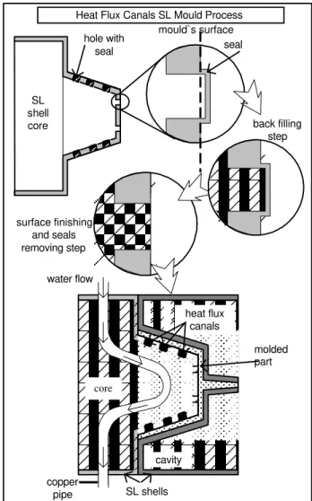
The alternative technique to cool down SL moulds proposed in this work, allows heat extraction from the moulded part through direct contact between the injected polymer and the back filling material. The process starts with the design of the SL shell moulds. In this particular case, the shell CAD models contain small holes with very small thickness seal walls on its cavity surface to make the back filling process possible. After the alloy solidification, during the post processing procedures, the seal walls are removed and the metallic surface can easily be polished. This last procedure will promote the contact between the back filling alloy and the moulded part. It is possible and advisable to use a water-cooling system to increase heat extraction from the mould. The sequence to obtain the mould is presented in Fig. 3. The design of the heat flux canals must be carefully planned considering geometric aspects of the part and the use of ejector pins. For this, an analysis of the injection process can be carried out, using numerical simulation, to determine the regions of higher heat concentration. From the practical point of view, the placement of the holes in small features can make mould finishing difficult, so it must be prudently studied.
Heat Flux Canals SL Mould Process
molded part water flow
cavity
copper
pipe SL shells
heat flux canals
core
back filling step
surface finishing and seals removing step
SL shell core
hole with
seal seal
The Finite Element Analyses Procedures
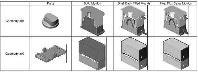
To validate the efficiency of the cooling technique, transient thermal FEA of two moulds designed in agreement with the procedure described above were performed. The results obtained were compared with two other analyses obtained from shell and solid moulds. The shell moulds were designed based on Decelles & Barrit (1997) procedures such as the shell thickness.
Based on previous researches (Gomide, 2000) two geometries were chosen and the same moulding process conditions were considered. The examples are illustrated in Table 1. Initially CAD models of the parts in SolidWorks2001 were generated. Previous rheological analyses of each part were performed using Moldflow 1.1 Plastics Insight to determine hot spots of the mould during the
injection moulding cycle. The results were used to define the positioning the heat flux canals. The models (considering the problem symmetry) were imported to Ansys 5.6.1 package in IGES format file and the discrete models were obtained using a quadratic solid element. To minimize the influence of the finite element model in the results the same mesh refinement for all studied models was considered. Boundary conditions for the initial temperature in the
mould (250C) and moulded part (1700C) were applied, keeping the
cooper pipes temperature (250C) constant along the process. As
shown in Fig. 4, constrains boundary conditions were applied in coincident nodes generated on contact surfaces to allow the heat transference from the injected part to the mould. The model was evaluated in intervals from 0 to 120 seconds, considering a time increment of 1 second.
moulded part backfill SL shell
node coincident
nodes surface contact
Figure 4. Schematic coincident nodes in the analysis mesh.
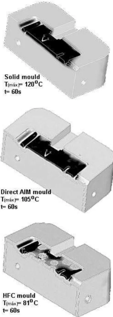
The objective during the numerical analyses was to determine the moulds temperature variation along the time. The results obtained were used to compare the systems cooling efficiency. As described above, the numerical model used consider that the heat flux starts after the cavity is completely filled. A similar approach was proposed and experimentally validated by Hopkinson & Dickens (2000) to perform transient thermal analysis in SL moulds. However, the boundary conditions used in this work refer to the temperature at beginning of the injection moulding process.
Results and Discussion
The results from the different analyses were compared taking reference points, in each mould, as close as possible. The difficulty to get precisely the same point in the three different moulds occurred due to the mesh changing for each geometry of the mould, although the same mesh refining has been considered. Figures 5 & 6 show plotted graphs of different curves of temperature versus time for one moulding cycle. It is easy to identify the lowest temperatures obtained in different regions using the heat flux canals to drain the heat from the part. The region on geometry #2, the worst region under heat flux canals effect, was taken to evaluate the exposure time of the SL resin to high temperatures during the injection moulding cycle. The region on geometry #1 is a mid point between two heat flux canals. Figure 7 shows the local effect of a heat flux canal, where the temperatures are lower.
An evaluation of the exposure time of the stereolithography resin to the high temperatures of the moulding cycle can be performed. From Figures 5 & 6 it is possible to verify that the HFC (heat flux canals) moulds show a reduction in the temperature for all regions that have been analysed. Taking a reference temperature (highest temperature inside the parts) to eject the parts from the moulds it is possible to take almost 35 seconds of advantage comparing to the other two methods analysed. It is clear that the global heat absorbed by the SL resin is lower and the degradation of the resin will be delayed. So it is possible to affirm that the SL tools life should be increased.
Table 1. Geometries and moulds used in the analyses.
Parts Solid Moulds Shell Back Filled Moulds Heat Flux Canal Moulds
Geometry #01
Geometry #1 - Region A
60 80 100 120 140 160 180
10 20 30 40 50 60 70 80 90
100 110 120
Time [seconds]
Temperature [celsius]
part_Solid part_DirectAIM part_HFC upper_shell_Solid upper_shell_DirectAIM upper_shell_HFC
Figure 5. Results obtained for the temperatures part and moulds surface for geometry #2.
Geometry #2 - Region B
20 40 60 80 100 120 140
10 20 30 40 50 60 70 80 90
100 110 120
Time [seconds]
Temperature [celsius]
upper_shell_HFC upper_shell_DirectAIM back_shell_HFC back_shell_DircetAIM
Figure 6. Results obtained for the temperatures part and moulds surface for geometry #1.
Figure 7. Heat flux canal effect (darkest = hottest).
Figure 8. Tested part used in the fill experiment.
Table 2. Properties of the three tested alloys.
Weight [%]
Bi Sn Pb Cd
Temp. Solidus [K]/[oC]
Temp. Liquidus
[K]/[oC]
50 12,5 25 12,5 343,15/
70
346,15/ 73
54 26 -- 20 375,15/
102
376,15/ 103
56,6 -- 43,5 -- 397,15 / 124
(Eutectic)
The low melting temperature of the alloys can be a problem to inject thermoplastics with higher melting points. The first alloy presented in Table 2 (50%Bi, 12.5%Sn, 25%Pb & 12.5%Cd) melted
in contact with polypropylene at 220oC. The other two alloys did not
have this problem.
Using the holes in the SL shell will result in stress concentrations that may cause early mould failure. Therefore it is necessary to develop a stress-strain analysis under the moulding cycle. To improve resistance it is advisable to increase the shell thickness of the mould. These are some of the next steps that are being in development at CIMJECT’s Laboratory.
Conclusions
The results of this work pointed out interesting facts regarding the cooling capacity of SL moulds. Despite the fact that the shell mould (“traditional” SL mould or “old” Direct AIM) is often more economical than the solid SL mould, it is clear that the heat of the moulded part is essentially extracted from the mould using air jet cooling after part ejection.
The heat flux canals are thermally more efficient than the other techniques that have been evaluated. Using this technique, it is possible to slow down the loss of SL resins mechanical strength, by minimising the exposure time of the resin to high temperatures. However, this technique has limitations concerning part geometry. The direct contact of the alloy with the part may cause marks on part
surface. For aesthetic use, heat flux canals should be placed just in
the core of the mould. A thin metallic layer over the cavity could help to avoid this problem and maybe increase the heat transfer to the back filling material.
As previously mentioned, it is still necessary to perform other types of analyses to get a better evaluation of the technique. The use of numerical techniques appears to be an efficient and inexpensive tool to evaluate the mould thermal performance. Nevertheless, a problem that has to be solved is to define a reliable methodology to estimate the ejection forces in the cavity with the aid of finite element analysis. After that, it will be possible to carry out stress-strain analyses in SL moulds and to perform a complete evaluation and optimisation of its design to apply in experimental tests.
Practical results comparing the techniques will be presented as soon as they have been completely finished and evaluated at CIMJECT.
Acknowledgements
The authors would like to thank CAPES, CNPq and FINEP for financial and research scholarship support.
References
Cedorge, Thomas; Baut, Yann Le; Palmer, Anne; Colton, Jonathan. "Design Rules for Stereolithography Injection Molding Inserts". Proceedings of 8th European Conference on Rapid Prototyping and Manufacturing.
Nottingham, UK. pp. 193-209. July, 1999.
Decelles, P.; Barrit, M.. "Direct AIM, Prototype Tooling". White Paper. 3D Systems Inc.. Valencia, California, USA. 1997.
Dickens, Phill. "Rapid Tooling Techniques. Rapid Tooling’s Strategic Benefits & Risks – A Special EuroMold ’99 Conference". Frankfurt, Germany, Dec – 1999;
Gomide, Ricardo Borges. "Moulded Parts Manufacturing Using Thermoset Resin Moulds Produced by Stereolithography" (in portuguese). Master Dissertation submitted to Federal University of Santa Catarina. Florianópolis, SC, Brazil. May, 2000 (in Portuguese).
Hopkinson, Neil; Dickens, Phill. "Predicting stereolithography injection mould tool behaviour using models to predict ejection force and tool strength". International Journal of Production Research, v. 38 (16), 2000;