Rajesh C. Shah
Department of Mathematics Nirma Institute of Technology Sarkhej-Gandhinagar Highway Ahmedabad - 382 481, Gujarat State, India [email protected]M. V. Bhat
E-202, Riddhi Complex Near jodhpur Village Ahmedabad - 380 015 Gujarat State, IndiaAnalysis of a Porous Exponential
Slider Bearing Lubricated with a
Ferrofluid Considering Slip Velocity
A porous exponential slider bearing was studied with a ferrofluid lubricant whose flow is governed by Jenkins flow behaviour considering slip velocity at the porous interface. Expressions for dimensionless pressure, load capacity, friction on the slider, coefficient of friction and the position of the centre of pressure were obtained. Computed values were displayed in graphical from. The load capacity as well as friction decreased and the coefficient of friction increased when the slip parameter increased. But, increase in the material parameter caused decrease in load capacity and increase in friction as well as coefficient of friction. Increase in the slip parameter did not significantly affect the position of the centre of pressure. But, it shifted towards the bearing inlet for large values of the material parameter.Keywords: Porous, exponential slider, lubrication, ferrofluid, Jenkins model, slip
Introduction
The study of an inclined plane slider bearing is a classical one. Owing to elastic, thermal and uneven wear effects, the slider was found to bend. Cameron (1987) suggested that an exponential form of the slider to be nearest the true shape. With the advent of porous sintered metal, porous bearings were used in machines because of the advantages like their self-lubricating nature and cheapness. Introducing a porous matrix of uniform thickness backed by a solid wall to the stator, Prakash and Vij (1973) and Bhat (1982) analyzed an inclined plane slider bearing and an exponential slider bearing respectively. Use of porous matrix decreased the load capacity and friction force on the slider.1
One way of removing these defects was to use a ferrofluid as lubricant. Agrawal (1986) and Bhat and Patel (1991) studied an inclined plane porous slider bearing and an exponential porous slider bearing respectively, considering a ferrofluid lubricant with its flow governed by Neuringer-Rosensweig model. They found that such a lubricant caused increase in the load capacity of the bearings without affecting the friction force on the respective sliders.
Ram and Verma (1999) considered a porous inclined plane slider bearing with a ferrofluid lubricant flowing following the simplified Jenkins model. The model introduced a material constant unlike the Neuringer-Rosensweig model. So, we feel it is realistic. Shah and Bhat (2002a) analyzed an impermeable exponential slider bearing with the Jenkins lubricant flow model. When the material constant increased , the load capacity decreased and the coefficient of friction increased without affecting the friction force on the slider as well as the position of the centre of pressure.
All the investigators , assumed no-slip condition at the interface of film and porous matrix. According to Sparrow et al (1972) the above assumption was not true at the surface of a naturally permeable material made of foam or soft metal. Shah and Bhat (2002b) studied an inclined porous slider bearing using the above slip model . Owing to the slip velocity the load capacity and the friction force decreased.
In this paper we analyze an exponential porous slider bearing with a ferrofluid lubricant , its flow being governed by the Jenkins model and considering slip velocity at the film-porous interface.
Paper accepted July, 2003. Technical Editor: Atila P. Silva Freire.
Nomenclature
a = h2/h1
A = bearing length B = bearing breadth E = defined in Eq.(14) f = coefficient of friction F = friction on the slider G = defined in Eq.(13) h = film thickness h1 = minimum value of h h2 = maximum value of h H = magnitude of applied field H* = thickness of porous matrix k = permeability of porous matrix
K = defined in Eq.(10) to suit dimensions of both sides
M = magnetization vector p = film pressure
q = fluid velocity Q = defined in Eq.(18) s = slip constant
u = x component of the velocity of film fluid U = velocity of slider
W = load capacity x,y,z = coordinates X = x/A
ζ = fluid viscosity
µ0 = free space permeability
µ*
= defined in Eq.(11)
ψ = defined in Eq.(11)
f = defined in Eq. (21)
F
= defined in Eq. (20)h
= h / h1Η = applied magnetic field p = defind in Eq. (11) s = sh1
W = defined in Eq. (19)
Χ = x coordinate of the centre of pressure Y = X/A
µ = magnetic susceptibility
R. C. Shah and M. V. Bhat
J. of the Braz. Soc. of Mech. Sci. & Eng. Copyright 2003 by ABCM July-September 2003, Vol. XXV, No. 3 / 265 2
α = material constant
β2
= defined in Eq.(11)
γ*
= defined in Eq.(11)
ρ = fluid density
Analysis
The equations of the simplified Jenkins model for a steady ferrofluid flow, neglecting inertia terms, as in Ram and Verma (1999)
(
)
){
( )
}
02 ( 2 2 0 2 = ∇ ∇ ρα + ∇ • µ + ∇ ζ + ∇
− q M H Mx xqxM M
x
/
p , (1)
0
= •
∇ q , (2)
0
x =
∇ H , (3)
H
M=µ , (4)
(
+)
=0•
∇ H M , (5)
where p , ζ, q, µ0, M, ρ, α 2
, M , H , µ are the film pressure , fluid viscosity, fluid velocity, free space permeability, the magnetization vector, fluid density, material constant, magnitude of M , magnetic field vector and magnetic susceptibility respectively.
With the usual assumptions of lubrication , Eqs. (1) and (2) yield the one-dimensionless equation governing the lubricant flow in the film region as
µ µ
− ∂ ∂ ζ µ ρα − ζ = ∂ ∂ 2 H p x 2 H 1 1 z
u 0 2
2 2
2
, (6)
where u is the film fluid velocity in the x-direction and H is the magnetic field strength.
The bearing displayed in Fig.1 consists of an impermeable slider in an exponential form moving with a uniform velocity U in the x-direction. The stator lies along the x-axis and has a porous matrix of uniform thickness H*. The bearing length is A and breadth B , where A <<B. The lubricant film thickness h in the z direction is taken as
Figure 1. Porous exponential slider bearing.
h = h2 e
- ( x ln a ) / A
, 0 ≤ x ≤ A, (7) where h1 and h2 are minimum and maximum values of h with a = h2 / h1.
Solving Eq. (6) under the simplified slip boundary conditions proposed by Sparrow et al (1972) with s as slip constatnt depending on the porosity and permeability of the porous matrix,
h z when U u , 0 z when z u s 1 u 0 z = = = ∂ ∂ = =
, (8)
we obtain u. Substituting this value of u in the integral form of the continuity equation in the film region, using the continuity of velocity components across the film at the surface z=0 and the porous interface, we obtained the Reynolds type Eq. in this case as
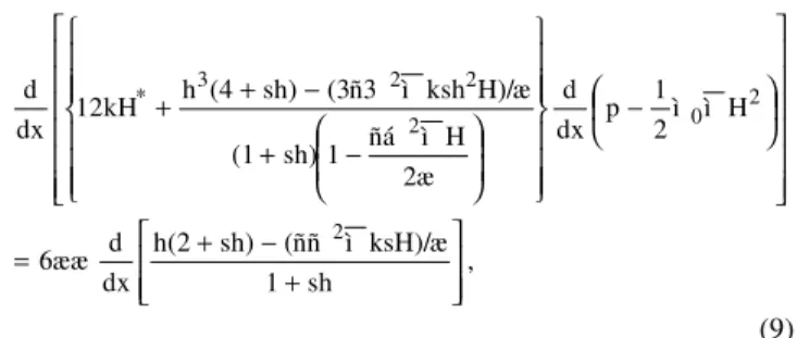
, sh 1 ksH)/æ ì (ññ sh) h(2 dx d 6ææ H ì ì 2 1 p dx d 2æ H ì ñá 1 sh) (1 H)/æ ksh ì (3ñ3 sh) (4 h 12kH dx d 2 2 0 2 2 2 3 * + − + = − − + − + + (9)
k being the permeability of porous matrix. Defining the magnitude of the applied magnetic field as given by the Eq.
) x -A ( K x
H2=
,
(10)
its inclination φ to the x-direction as in Agrawal (1986), and using the dimensionless quantities
, h 6k ã , æU KAh ì ì ì æUA p h p , 2æ A K ì ñá â sh s , h h h , h kH ø , A x X 2 1 * 2 1 0 * 2 1 2 2 1 1 3 1 * = = = = = = = = (11)
Eq.(9) transforms to
dX dE ) X 1 ( X 2 1 p dX d G dX
d * =
− µ −
, (12)
ψ + − β − + − β γ − + = 12 ) ) X 1 ( X 2 1 )( h s 1 ( ) X 1 ( X 2 h s 2 * ) h s 4 ( 3 h G
where , (13)
h s 1 ) X 1 ( X s 2 ) h s 2 ( h 6 E * 2 + − γ β − +
= , (14)
a ln X -e a .
h= . (15)
Solutions
Solving Eq.(12) under the boundary conditions
p = 0 when X = 0, 1, (16) we obtain
(
)
dXX 1 G Q E X 1 X * 2 1
∫
∫
= 1
0 1
0
dX G
1 dX G E
Q
where . (18)
The load capacity W of the bearing, friction force on the slider F, coefficient of friction f and the x-coordinate X of the centre of pressure can be expressed in dimensionless forms as
dX G
Q E X 12 B UA
W h W
1
0 *
2 2
1 = µ −
∫
−ζ
= , (19)
(
)
(
)
dX) X 1 ( X 1
( h s 1 G 2
Q E ) h s 2 ( h h
s 1
s UAB
F h F
1
0 2
1
∫
− β − +
− +
+ + = ζ
= ,
(20)
W F h Af f
1
=
= , (21)
−
− µ =
= 1
∫
0 2 *
dX G
Q E X 2 1 24 W
1 A X
Y . (22)
Results and Discussion
The present analysis reduces to that of Bhat and Patel(1991) by setting β2 =1 / s =0 in it while it reduces to Bhat(1982) by setting 1 / s = β2=µ* = 0 in it.
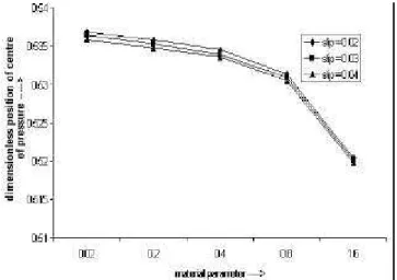
Expressions for dimensionless pressure p, load capacity W, friction force on the slider F, coefficient of friction f and for the position Y of the centre of pressure are obtained in Eq. (17), and Eq.(19) to (22). Values of W,F, f, and Y are displayed in Figs. 2-5 for different values of the slip parameter 1 / s and the material parameter β2.
Figure 2. Dimensionless load capacity W for different values of the slip parameter 1 / s and material parameter ββ2 for ψψ = 0.001 , µµ* = 1, γγ*= 0.3,
a = 2.
Figure 3. Dimensionless friction F for different values of 1 / s and ββ2 for
ψ
ψ=0.001 , µµ* = 1, γγ*= 0.3, a = 2.
Figure 4. Dimensionless coefficient of friction f for different values 1 / s and ββ2 for ψψ = 0.001 , µµ* = 1, γγ* = 0.3, a = 2.
Figure 5. Dimensionless position of the centre of pressure Y for different values of 1 / s and ββ2 for ψψ = 0.001 , µµ* = 1, γγ* = 0.3, a = 2.
R. C. Shah and M. V. Bhat
J. of the Braz. Soc. of Mech. Sci. & Eng. Copyright 2003 by ABCM July-September 2003, Vol. XXV, No. 3 / 267 The Reynolds type Eq.(9) used by us is the complete equation.
However, Ram and Verma (1999) approximated it and obtained expressions for p and W , computing the values of W only. They found that W increased with β2 in contrast to our results (2002b) perhaps because they assumed the unrealistic value H* / h0 = 0.5.
Comparing the present results with those for an inclined plane porous slider bearing of Shah and Bhat (2002b) we find that the exponential porous slider bearing has more load capacity , friction and coefficient of friction than the former.
Conclusions
An exponential porous slider bearing has more load capacity , friction and the coefficient of friction than the corresponding inclined plane porous slider bearing. The decrease in load capacity of the bearing owing to the slip velocity as well as the material parameter can be made good by increasing the magnetization of the fluid.
Acknowledgement
The authors are grateful to the referee for his valuable comments.
References
Agrawal, V.K.,1986, “Magneticfluid based porous inclined slider bearing ”, Wear, Vol.107, pp.133-139.
Bhat, M.V., 1982, “Hydrodynamic lubrication of an exponential porous slider bearing” , S.P.Uni. Res. J., Vol. 1, pp. 93-96.
Bhat, M.V. and Patel, R.R., 1991, “Analysis of an exponential porous slider bearing lubricated with magnetic fluid”, J. Eng. Technol. S.P.Uni., Vol. 6 , pp. 19-21.
Cameron, A., 1987,” Basic lubrication theory”, Wiley Estern Ltd, p. 62. Prakash , J. and Vij, S.K.,1973, “Hydrodynamic lubrication of a porous slider”, J. Mech. Eng. Sc. , Vol. 15 , pp. 232-234.
Paras Ram and Verma, P.D.S., 1999, “Ferrofluid lubrication in porous inclined slider bearing”, Indian J. Pure Appl. Math., Vol. 30 , pp. 1273-1281.
Sparrow, E.M., Beavers, G.S. and Hwang, I.T., 1972,” Effect of velocity slip on porous walled squeeze films”, J. Lubr. Technol., Vol. 94, pp. 260-265.
Shah , R.C. and Bhat, M.V., 2002a, “Exponential slider bearing lubricated with ferrofluid”, Proceeding of Mediterranean Trib. , pp. 99-103.
The following are the corrections in the paper entitled " Analysis of a Porous Exponential Slider Bearing Lubricated with a Ferrofluid Considering Slip Velocity by Rajesh C.Shah and M.V.Bhat" published in Vol. XXV, No.3, July-September 2003.
1. Equation (1) should read as
(
)
{
(
)
}
0M 2
ρα
µ
ζ
p
2
0
2 =
⎥⎦ ⎤ ⎢⎣
⎡ × ∇× ×
× ∇ + ∇ • + ∇ + ∇
− q M H M q M
2. Equation (9) should read as
3. Equation (11) should read as
⎥ ⎥ ⎦ ⎤ ⎢
⎢ ⎣ ⎡
+ρα µ ζ
− + ζ
=
⎥ ⎥ ⎥ ⎥ ⎥
⎦ ⎤
⎢ ⎢ ⎢ ⎢ ⎢
⎣ ⎡
⎟ ⎠ ⎞ ⎜
⎝
⎛ − µ µ
⎪ ⎪ ⎭ ⎪ ⎪ ⎬ ⎫
⎪ ⎪ ⎩ ⎪ ⎪ ⎨ ⎧
⎟⎟⎠ ⎞ ⎜⎜⎝
⎛
ζµ ρα − +
ζ µ
ρα − + +
sh 1
/ ) ksH (
) sh 2 ( h dx
d U 6
H 2 1 p dx
d
2 H 1
) sh 1 (
/ ) H ksh 3
( ) sh 4 ( h kH 12 dx
d
2 2 0 2
2 2 3
*
2 1 * 2 1 0 *
2 1 2
2 1 1 3 1 *
h k 6 , U KAh
, UA
p h p , 2
A K sh
s , h
h h , h kH , A x X
= γ ζ µ µ = µ
ζ = ζ
µ ρα = β = = =
Ψ =
=