Jales Almeida Silva
Engenheiro Civil da Colmeia Consultoria e Projetos Goiânia – Goiás – Brasil
Marília Gonçalves Marques Professora-Mestre
Universidade Federal de Viçosa - UFV Rio Paranaíba – Minas Gerais – Brasil [email protected]
Leandro Mouta Trautwein Professor-Doutor
Universidade Estadual de Campinas – UNICAMP Faculdade de Engenharia Civil, Arquitetura e Urbanismo, Departamento de Estruturas Departamento de Estruturas
Campinas – São Paulo – Brasil [email protected]
Ronaldo Barros Gomes Professor Titular
Universidade Federal de Goiás - UFG Escola de Engenharia Civil e Ambiental Goiânia – Goiás - Brasil
Gilson Natal Guimarães Professor Titular
Universidade Federal de Goiás - UFG Escola de Engenharia Civil e Ambiental Goiânia – Goiás - Brasil
Punching of reinforced
concrete flat slabs with
holes and shear reinforcement
Abstract
Punching shear is a possible type of failure that occurs in reinforced concrete lat slabs, which can develop with an ultimate load below lexural capacity. Several research-ers have studied the punching resistance of lat slabs over recent years. Although they have made great advances, there are codes that show different approaches to a singular design. Some codes show that there exist contradictions, even in the simplest situations, such as concentric loads. Most codes prescribe empirical expressions based in a theoreti-cal model to analyze punching strength, but for lat slabs with holes around the column and shear reinforcement there are divergences between codes, justifying research in this area. This paper presents an experimental analysis of nine square reinforced concrete lat slabs under concentric loading (width: 1800 mm; thickness: 130 mm). The main variables used in the tests were: a) two square openings (150 mm) adjacent to the small-est side of the column and b) the use of shear reinforcement containing 3 layers, with 6 or 8 elements in each layer and radially distributed around the column. The research concludes that openings adjacent to the column affect punching shear strength, while the correct use of the shear reinforcement can minimize and even compensate this loss.
Keywords: punching, slabs, studs, holes.
http://dx.doi.org/10.1590/0370-44672017700022
Civil Engineering
Engenharia Civil
1. Introduction
The conventional structure system (slab-beam-column), for some situations, has been substituted by the slab-column system in civil construction projects. The slab-column system does not have the support of the beams, where the slabs are supported directly onto the column. This structural concept brings advantages, such as facilitating the use of the form-work in order to reduce cuts inluenced by beams. This produces greater agility in the construction process with a de-crease in costs regarding material waste.
The level of detail given to the reinforce-ment is simpler and consequently easier to execute, whereby there also exists the possibility of adapting the site for other ends due to the inexistence of beams.
On the other hand, this structure does have its disadvantages in using lat slabs. As beams do not exist, there may occur a reduction in the global stability of the structure, and as the lat slab is normally less rigid than a conventional slab (with beams), it is open to greater vertical displacements, when compared
to conventional slabs.
slab, where the column is supported on a slab. Another region that is also sub-ject to damage through punching is the meeting point between the column and foundation. This damage may occur in an abrupt and fragile manner, without giving warning.
Holes adjacent to the columns for the passage of ducts used for electrical and hydraulic installarions can ag-gravate the rupture through punching shear. Research performed in Brazil and the exterior evaluated the use of stud type reinforcement to increase resistance to punching. The studies evaluate slabs with variable loads, holes and bending moment.
There have been research studies
that resulted in some empirical for-mulations based on shear stress and control perimeter. A formulation is differentiated one from another basi-cally in terms of position and form of the control perimeter. The irst ratio-nal theory concerning punching was presented by KINNUNEN & NYL-ANDER (1960), based on circular slab trials without reinforcement.
Ha et. al. (2015) studied eight lat slabs with round holes, varying the amount and position of the hole. The authors concluded that the amount and position modifies the failure surface mode. Holes adjacent to the column re-duce the shear strength of the slabs, and holes positioned at the column corner
can result in further reduction.
In order to make the column/slab connection safer, an increase in the ductility and the resistance capacity of a lat slab’s shear reinforcement is used to avoid punching. Research studies such as those by GOMES e REGAN (1999), ANDR ADE (2000), SILVA (2003), SOUZA (2009) and BORGES (2013), FERREIRA (2010) e TRAUTWEIN (2011) demonstrate that the use of shear reinforcement can be extremely eficient in preventing punching failure, even to the point of changing the rupture due to lexure. This study aimed to provide in-creased punching resistance when using a shear reinforcement stud type, and when using an increased column perimeter.
2. Materials and methods
This paper shows a summary of the experimental results for nine square reinforced concrete lat slabs with the same dimensions, and lexural reinforce-ment with a load on their center. All of the slabs were square with side lengths of 1800 mm and a thickness of 130
mm (SILVA, 2003). A study is made of the central punching failure scenario, a common situation in the central columns of buildings with lat slabs, and with a symmetric load, which is transmitted to the slab without irregularity.
The slabs and the adopted test
arrangement correspond to an area of negative bending on the column, ap-proximately equal to 1/5 of the span in real scale and equivalent to a span of 4125 mm, considering a situation of in-ternal column and symmetrical loading, as shown in Figure 1.
Figure 1
Hypothetical frame featuring
the region studied in ANDRADE (1999).
2.1 Characteristics of the trial slabs
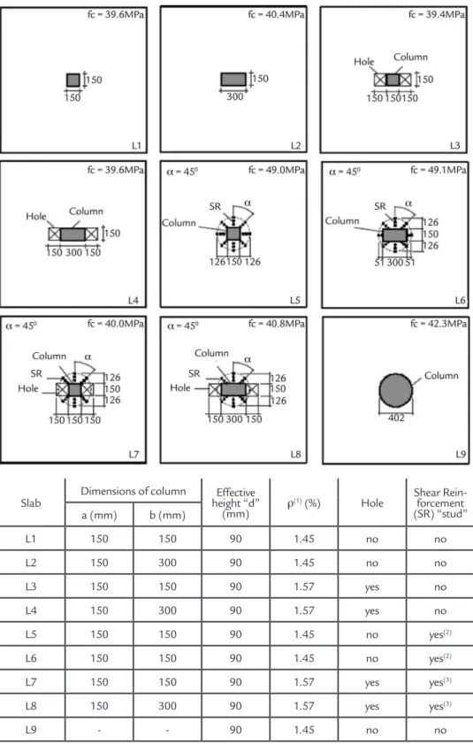
The main characteristics of the slabs are: a) effective height of 90 mm, b) the existence of two holes of 150 mm x 150 mm arranged adjacent to the col-umn, c) the use of shear reinforcement (SR) with a radial distribution in 3 layers and diameter φ = 8 mm, d) dimensions of the column with a constant side "a" equal to 150 mm and the other side "b"
with values of 150 mm and 300 mm, as shown in Figure 2. The high ratio lexural reinforcements were adopted to avoid lexural failure. In the slabs without holes the ratio was 1.45 % and in the slabs with holes was 1.57 %. This difference is due to the addition of two perpendicular bars in the direction of the holes.
Figure 2 Main features of the slabs under study.
Source: Silva, 2003
Slab
Dimensions of column Effective height “d”
(mm) ρ
(1) (%) Hole Shear Rein-forcement
(SR) “stud” a (mm) b (mm)
L1 150 150 90 1.45 no no
L2 150 300 90 1.45 no no
L3 150 150 90 1.57 yes no
L4 150 300 90 1.57 yes no
L5 150 150 90 1.45 no yes(2)
L6 150 150 90 1.45 no yes(2)
L7 150 150 90 1.57 yes yes(3)
L8 150 300 90 1.57 yes yes(3)
L9 - - 90 1.45 no no
(1) ρ=√(ρx ρy ), reinforcement rate, calculated with a width equal to 1034 mm; (2) 8 lines; (3) 6lines.
Table 1 Slab features.
2.2 Test arrangement
The load was applied upward f rom a jack , w it h a c apacit y of 1500 kN, placed at the middle of the bottom face of the slab, and the
reac-tions were provided by four ties ixed to the strong loor and through a set of steel beams (beams 1 and 2 of Figures 3 and 4) onto a reaction slab at each
edge. This reaction was performed through 8 equidistant points positioned in a circumference with a radius equal to 825 mm.
2.3 Details of the tested models
The lexural reinforcement used on the slabs presents different details due to the holes and loading areas (columns). For the slabs without holes, the negative reinforcement (top) is composed of an
orthogonal mesh of 19 bars of 12.5 mm in diameter (CA-50) in each direction. The positive reinforcement (bottom) is composed of an orthogonal mesh of 11 bars of 6.3 mm in diameter (CA-50 steel)
Figure 3
Test arrangement (Top view).
Source: Silva, 2003.
Figure 4
Test arrangement (side view).
Source: Silva, 2003.
Only slabs L5, L6, L7 and L8 used shear reinforcement (Table 1) of the stud type, where steel bars CA-50 (φ = 8 mm and a length of 105 mm) were welded at their extremities to steel
plates of 30 mm in length and 100 mm in thickness. These studs were made through a manual welding process with a coated electrode of type “OK 48.04” of 3.5 mm from ESAB. Figure 5 shows
a scheme with the dimensions of the shear reinforcement and a photograph that illustrated the positioning of the shear reinforcement in relation to the lexural reinforcement.
Figure 5
Shear Reinforcement.
In all slabs, the concrete had cylinder compressive strength between 39.4 MPa and 49.4 MPa. The mix proportion to
weight ratio used to fabricate the concrete for all slabs was calculated by the company Betonmaster – Concrete and Artefacts from
Cement Ltda. The superplasticizer additive was added minutes before concreting to improve the workability of the mixture.
3. Results and discussion
The experimental results included the ultimate load, mode of failure and cracking pattern.
3.1 Load and failure mode
The loads were applied in incre-ments and tested up to failure for all slabs
and had punching failure. The failure load adopted was the maximum value
reached in the load cell, Table 2.
Slab fc (MPa)
Dimensions of column
C(1)
(mm) ρ (%) Hole(2) A.C.(3) Pu (kN)
a (mm) b (mm)
L1 39.6 150 150 600 1.45 no no 273
L2 40.4 150 300 900 1.45 no no 401
L3 39.4 150 150 600 1.57 yes no 225
L4 39.6 150 300 900 1.57 yes no 350
L5 49.0 150 150 600 1.45 no yes(4) 420
L6 49.4 150 150 600 1.45 no yes(4) 452
L7 40.0 150 150 600 1.57 yes yes(5) 325
L8 40.8 150 300 900 1.57 yes yes(5) 350
L9 42.3 402(6) 1262 1.45 no no 525
(1) Perimeter of the column;
(2) Two holes of 150x150 mm placed adjacent to the side of the column; (3) Shear reinforcement of the stud type, φ = 8mm, with 3 layers; (4) 8 lines; (5) 6 lines;
(6) Circular column, value of diameter of the column.
Table 2 Slab Rupture Loads.
The failure load of the tested slabs obtained results depending on the pe-rimeter of the column, and the number of holes with the use or not of shear reinforcement. The slabs with the same characteristics with higher perimeter and shear reinforcement increased the failure loads of the slabs.
For slabs L1, L2 and L9, without holes and shear reinforcement, a notable increase was observed in the failure load of slabs L2 of 46 % and L9 92 %, when compared to the rupture load of slab L1. This increase occurs, in all probability, because of the increase of the column perimeter on slab L5.
The strength drop due to the
ex-istence of the two holes arranged adja-cent to the smaller sides of the column, in relation to the slabs without holes (L1-b/a = 1, L2-b/a = 2), was 48kN and 51kN, respectively. Note for these models that the load loss was practically constant for a "b/a" ratio of less than 2.
The reduced failure load due to the existence of holes placed adjacent to the column and without shear reinforcement, L3 and L4, were 18 % and 13 % respec-tively. However, when shear reinforcement is used, as with L7, the load increased by 16 % compared to the L1 reference slab. In terms of the slab without the hole but with shear reinforcement (L5), the increase of the failure load reached 35 %.
When comparing the failure loads of the slabs L8 (with two holes and shear reinforcement) and L4 (with two holes and without shear reinforcement), it was verified that the shear reinforcement adopted was ineffective, since it did not contribute any increase in the failure load.
Slabs L1, L2 and L12 showed signs of failure surface on the face of the col-umn in two directions. The failure sur-face around the holes of slabs L3 and L4 initiated at the column face and extended to the other side of the hole. In the slabs that had shear reinforcement (L5, L6, L7 and L8), the failure surface initiated after the last layer of studs, constituting an external rupture.
3.2 Cracks
The irst visually apparent cracks were radial and these occurred in all slabs for a load between 50 kN and 100 kN, as presented on Table 3. Noted
here is that the irst radial crack started between of 17 % to 19 % of the failure load for slabs without holes, and from 22 % to 24 % of the ultimate load for
Slab Pu (kN) Pu’(1) (kN) Pu’/Pu (%)
L1 273 50 18.3
L2 401 75 18.7
L3 225 50 22.2
L4 350 75 21.4
L5 420 75 17.6
L6 452 75 16.6
L7 325 75 23.1
L8 350 75 21.4
L9 525 100 19.0
(1) Load at the moment of the first visible radial crack
Table 3
Comparisons on the
appearance of the first radial crack.
Figure 6
Crack pattern after the
failure of slabs L1, L5, L7 and L8.
Source: Silva, 2003.
After the rupture, the slabs pre-sented a similar development regarding radial cracks and with some difference in
relation to the circumferential cracks. For slabs L3 and L6, the appearance of the circumferential cracks was considerable,
practically surrounding the entire loading area and the radial cracks arrived near the supports.
4. Conclusions
The design of reinforced concrete flat slabs requires special care for punching shear, especially with the presence of holes near the column. The ultimate load at these columns supporting lat slabs may be distinctly below the lexural capacity and with a brittle failure. All the slabs tested had punching shear failure, and the research herein was directed to this failure mode. The slabs with shear reinforcement pre-sented external failures, with the failure surface initiating after the last layer of the shear reinforcement.
The existence of holes adjacent to
the column can affect the strength to the punching of lat slabs. Results show that the failure load decreased in up to 13%, when the strength portion of the concrete is reduced in the critical region, with two square holes of 150 mm side by side.
The process associated with the appearance of radial cracks and the development of circumferential cracks followed differentiated characteristics for slabs with and without holes and shear reinforcement. For slabs without shear reinforcement, the circumferential crack appeared at 26 % to 48 % of the failure load, and at 33 % to 86 % for the
slabs with shear reinforcement.
The results also show that the use of this shear reinforcement can be a pos-sibility to increase the punching strength in lat slabs with holes. This increase may even be higher when compared to slab without shear reinforcement and without holes (19 % - from slab L7 to L1).
Received: 07 february 2017 - Accepted: 03 july 2017.
References
ANDRADE, M.A.S. Punching of lat slabs – study of the positioning of shear
reinfor-cement in relation lexural reinforreinfor-cement. Goiânia: Escola de Engenharia Civil /
UFG, 1999. (Dissertação de Mestrado).
ANDRADE, J.L.S. de. Experimental investigation on open stirrups with different
in-clinations in reinforced concrete lat slabs. Brasília, Brazil: Universidade de Brasília,
2000. 142 p. (MSc. Thesis).
BORGES L.L.J., MELO G.S., GOMES R.B. Punching shear of reinforced con-crete lat plates with openings. ACI Structural Journal, v.110, n. 4, p. 1-10. July-Aug. 2013.
BRAZILIAN ASSOCIATION OF TECHNICAL STANDARDS (ABNT). (2014) NBR 6118: Standard for concrete Stuctures Design (in Portuguese). Rio de Janeiro. GOMES, R. B.; REGAN, P. E. Punching resistance of RC lat slab with shear
reinforce-ment, Journal of Structural Engineering. New York, EUA, v.125, p. 684-692, 1999. FERREIRA, M. P. Punching of concrete lat slabs with shear reinforcement and unba-lanced moment. Brasília: Universidade de Brasília, 2010. 299 p. (Tese de Doutorado em Engenharia Civil).
HA,T., LEE, M., PARK, J., KIM, D. Effects of openings on the punching shear strength of RC lat-plate slabs without shear reinforcement. The Structural Design of Tall and
Special Buildings. John Wiley & Sons, Ltd. p. 895-911, 2015.
KINNUNEN, S., NYLANDER, H. Punching of concrete slabs without Shear Reinfor-cement. Civil Engineering n. 6. Stockholm, Transactions of The Royal Institute of
Technology. n. 158, 1960. 112 p.
REGAN, P.E. Punching tests of concrete slabs with riss star shear reinforcement
for riss AG. London: School of Architecture & Engineering, University of
Westminster, 1993.
SILVA, J.A. Punching of lat slabs – rectangular columns, openings and shear
reinforcement. Goiás: Universidade Federal de Goiás, 2003. (MSc. Thesis).
SOUZA, R. M., MELO, G. S., GOMES, R. B. Punching shear in reinforced concrete with hole adjacent to the column and moment transfer. In: BRAZILIAN CONCRE-TE CONGRESS - IBRACON, 51, 2009. Curitiba, Brazil.
TRAUTWEIN, L. M., BITTENCOURT, T. N., GOMES,R.B., BELLA, J.C.D. Pun-ching strength of lat slabs with unbraced shear reinforcement. ACI Structural