ScienceDirect
Available online at www.sciencedirect.com
Procedia Structural Integrity 17 (2019) 547–554
2452-3216 2019 The Authors. Published by Elsevier B.V. Peer-review under responsibility of the ICSI 2019 organizers. 10.1016/j.prostr.2019.08.073
10.1016/j.prostr.2019.08.073 2452-3216
© 2019 The Authors. Published by Elsevier B.V.
Peer-review under responsibility of the ICSI 2019 organizers.
ScienceDirect
Structural Integrity Procedia 00 (2019) 000–000
www.elsevier.com/locate/procedia
2452-3216 © 2019 The Authors. Published by Elsevier B.V. Peer-review under responsibility of the ICSI 2019 organizers.
ICSI 2019 The 3rd International Conference on Structural Integrity
An algorithm for fatigue crack growth applied to mixed and biaxial
mode loadings
R. Baptista
a,b,*, V. Infante
c, M. Freitas
caCDP2T and Department of Mechanical Engineering, Setúbal School of Technology, Instituto Politécnico de Setúbal, 2910-761 Setúbal,
Portugal
bIDMEC, Escola Superior de Tecnologia de Setúbal, Instituto Politécnico de Setúbal, 2910-761 Setúbal, Portugal cIDMEC, Instituto Superior Técnico, Universidade de Lisboa, Lisboa, Portugal
Abstract
Fatigue is still one of the main concerns when dealing with mechanical components failure. While it is fundamental to experimentally determine the fatigue material behavior using standard specimens, testing large and complex component geometries can be complicated. In these cases, the Finite Element Method can be a cost-effective solution but developing fatigue crack growth models is still a complicated task. In order to solve this problem, an algorithm for automatic crack propagation was developed. Using three different modules, the algorithm can generate a complex Finite Element Method model including a fatigue crack; solve this model considering complex loading conditions, by applying the superposition method; and calculate the fatigue crack propagation rate, using it to update the original model. In order to benchmark this solution two different problems were analyzed, a modified compact tension specimen and a cruciform specimen. By modifying the compact tension specimen hole location and simulating an initial crack, it was possible to understand how mixed mode conditions influence the fatigue crack path. Different load ratios and initial crack directions on the cruciform specimen were analyzed. Increasing the load ratio will increase the crack deflecting angle. The obtain solutions were compared with experimental results, showing good agreement. Therefore the developed algorithm can be used to predict the fatigue crack growth behavior on complex geometries and when different types of loads are applied to the component.
© 2019 The Authors. Published by Elsevier B.V.
Peer-review under responsibility of the ICSI 2019 organizers.
Keywords: Fatigue; Crack propagation; Mixed mode; Automatic algorithm
ScienceDirect
Structural Integrity Procedia 00 (2019) 000–000
www.elsevier.com/locate/procedia
2452-3216 © 2019 The Authors. Published by Elsevier B.V. Peer-review under responsibility of the ICSI 2019 organizers.
ICSI 2019 The 3rd International Conference on Structural Integrity
An algorithm for fatigue crack growth applied to mixed and biaxial
mode loadings
R. Baptista
a,b,*, V. Infante
c, M. Freitas
caCDP2T and Department of Mechanical Engineering, Setúbal School of Technology, Instituto Politécnico de Setúbal, 2910-761 Setúbal,
Portugal
bIDMEC, Escola Superior de Tecnologia de Setúbal, Instituto Politécnico de Setúbal, 2910-761 Setúbal, Portugal cIDMEC, Instituto Superior Técnico, Universidade de Lisboa, Lisboa, Portugal
Abstract
Fatigue is still one of the main concerns when dealing with mechanical components failure. While it is fundamental to experimentally determine the fatigue material behavior using standard specimens, testing large and complex component geometries can be complicated. In these cases, the Finite Element Method can be a cost-effective solution but developing fatigue crack growth models is still a complicated task. In order to solve this problem, an algorithm for automatic crack propagation was developed. Using three different modules, the algorithm can generate a complex Finite Element Method model including a fatigue crack; solve this model considering complex loading conditions, by applying the superposition method; and calculate the fatigue crack propagation rate, using it to update the original model. In order to benchmark this solution two different problems were analyzed, a modified compact tension specimen and a cruciform specimen. By modifying the compact tension specimen hole location and simulating an initial crack, it was possible to understand how mixed mode conditions influence the fatigue crack path. Different load ratios and initial crack directions on the cruciform specimen were analyzed. Increasing the load ratio will increase the crack deflecting angle. The obtain solutions were compared with experimental results, showing good agreement. Therefore the developed algorithm can be used to predict the fatigue crack growth behavior on complex geometries and when different types of loads are applied to the component.
© 2019 The Authors. Published by Elsevier B.V.
Peer-review under responsibility of the ICSI 2019 organizers.
Nomenclature
β initial crack angle ∆𝑎𝑎 crack increment
∆𝑁𝑁 elapsed number of cycles ∆𝐾𝐾𝑒𝑒𝑒𝑒 crack diving force
θ crack propagation direction
λ biaxial load ratio
φ load phase
σ nominal applied stress
σθθ tangential stress
σrθ radial stress
a crack length
KI mode I stress intensity factor
KII mode II stress intensity factor
r radial distance to crack front
1. Introduction
Fatigue crack growth (FCG) is one of the major causes for structural failure, Dirik et al. (2018). Therefore, accurate crack path and fatigue life determination is a fundamental part of structural project and design. Simple structures can be analyzed considering only pure mode I or mode II crack propagation, but more complex structures are subjected to mixed mode FCG. Mixed mode FCG can be introduced by design details, as hole and notches, or by complex loading, as in-plane biaxial normal stress. Some structures are subjected to both effects, like aircraft panels, where understanding the crack propagation behavior is fundamental, Armentani et al. (2011). Experimental testing is important, but can be very expensive, when full sized structural details must be manufactured. Developing algorithms for automatic FCG analysis enables Finite Element Analysis (FEA) to be used, in order to predict crack paths and fatigue lives on complex geometries and under complex loading, before specimen testing.
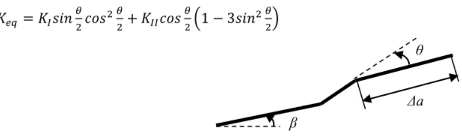
In our previous work, Baptista et al. (2019), an algorithm for automatic FCG analysis was developed. The algorithm was based on the Maximum Tangential Stress (MTS) criterion, originally defined by Erdogan et al. (1963). Now our algorithm has been improved and expanded, allowing for other criteria to be used, enabling for more complex and accurate FCG simulations. Considering the crack of Figure 1, according to MTS criterion, crack propagation occurs when tangential stress (𝜎𝜎𝜃𝜃𝜃𝜃) reaches a critical value, while radial stress (𝜎𝜎𝑟𝑟𝜃𝜃) is zero.
𝜎𝜎𝜃𝜃𝜃𝜃= 𝐾𝐾𝐼𝐼 √2𝜋𝜋𝑟𝑟𝑐𝑐𝑐𝑐𝑐𝑐3 𝜃𝜃2− 𝐾𝐾𝐼𝐼𝐼𝐼 √2𝜋𝜋𝑟𝑟3𝑐𝑐𝑠𝑠𝑠𝑠 𝜃𝜃 2𝑐𝑐𝑐𝑐𝑐𝑐2 𝜃𝜃2 (1) 𝜎𝜎𝑟𝑟𝜃𝜃= 𝐾𝐾𝐼𝐼 √2𝜋𝜋𝑟𝑟𝑐𝑐𝑠𝑠𝑠𝑠 𝜃𝜃 2𝑐𝑐𝑐𝑐𝑐𝑐2 𝜃𝜃2+ 𝐾𝐾𝐼𝐼𝐼𝐼 √2𝜋𝜋𝑟𝑟𝑐𝑐𝑐𝑐𝑐𝑐 𝜃𝜃 2(1 − 3𝑐𝑐𝑠𝑠𝑠𝑠2 𝜃𝜃2) (2) 𝜕𝜕𝜎𝜎𝜃𝜃𝜃𝜃 𝜕𝜕𝜃𝜃 = 0, 𝜕𝜕2𝜎𝜎𝜃𝜃𝜃𝜃 𝜕𝜕𝜃𝜃2 < 0 (3)
Where 𝜃𝜃 is the crack propagation direction according to the MTS criterion, and 𝐾𝐾𝐼𝐼 and 𝐾𝐾𝐼𝐼𝐼𝐼 are the Stress Intensity Factors (SIF) for mode I and mode II respectively. This criterion also allows to calculate the crack driving force, Xiangqiao et al. (1992):
𝐾𝐾𝑒𝑒𝑒𝑒 = 𝐾𝐾𝐼𝐼𝑐𝑐𝑐𝑐𝑐𝑐3 𝜃𝜃2− 𝐾𝐾𝐼𝐼𝐼𝐼3𝑐𝑐𝑠𝑠𝑠𝑠𝜃𝜃2𝑐𝑐𝑐𝑐𝑐𝑐2 𝜃𝜃2 (4) It is supported by several authors experimental work observations, and is especially useful to describe FCG under proportional loading conditions, Qian et al. (1996). When under non-proportional loading conditions the Maximum Shear Stress (MSS) criterion, Yu et al. (2017). According to this criterion, crack propagation occurs when 𝜎𝜎𝑟𝑟𝜃𝜃 reaches a critical value, allowing for crack propagation direction and crack driving force determination:
𝜕𝜕𝜎𝜎𝑟𝑟𝜃𝜃
𝜕𝜕𝜃𝜃 = 0, 𝜕𝜕2𝜎𝜎𝑟𝑟𝜃𝜃
𝐾𝐾𝑒𝑒𝑒𝑒 = 𝐾𝐾𝐼𝐼𝑠𝑠𝑠𝑠𝑠𝑠𝜃𝜃2𝑐𝑐𝑐𝑐𝑠𝑠2 𝜃𝜃
2+ 𝐾𝐾𝐼𝐼𝐼𝐼𝑐𝑐𝑐𝑐𝑠𝑠 𝜃𝜃
2(1 − 3𝑠𝑠𝑠𝑠𝑠𝑠2 𝜃𝜃2) (6)
Fig. 1. Crack increment and crack propagating direction.
Both criteria can now be easily used by our algorithm. Using FEA Contour Integral or eXtended Finite Element Method (XFEM) techniques, mode I and mode II SIF are extracted and crack propagation direction and crack driving forces are determined using equations (3) and (4) for proportional loading paths, or equations (5) and (6) for non-proportional loading paths.
The goal of our work was to test the algorithm under complex crack propagation conditions, including mixed mode crack propagation, due to the presence of a hole or under biaxial loading. The influence of different hole locations, crack propagation directions and fatigue lives were compared to experimental and numerical results obtained by different authors.
2. Materials and Methods
2.1. Algorithm for Crack Propagation
Fatigue crack propagation simulations performed in this paper, uses the automatic algorithm previously developed by Baptista et al. (2019). Like algorithms developed by other authors, it is based in three steps, Dirik et al. (2018). On the first step the FEA model is generated and linear elastic fracture mechanics parameters are calculated. Then, on a second step, the fatigue crack propagation rate is determined using the Paris law, Paris et al. (1963), or similar relationship. And finally, on a third step, the new crack tip coordinates are calculated, and the model is then update. The process is repeated until a desired ending condition is reached. Different authors have used this approach. Some solutions have clear disadvantages like requiring constant remeshing of the part, Dhondt (2014). Rabold et al. (2014) developed a similar algorithm using Abaqus and Python. Unfortunately, this algorithm uses a global model to calculate crack displacement, and a sub model of the crack front for SIF calculation. This enables the use of complex geometries, but requires two simulations per increment. Shi et al. (2010) solved a similar problem using only XFEM. Their algorithm does not require part remeshing, but in order to achieve satisfactory results requires the use of small elements size, becoming a very computer intensive application. Finally, using different modules Yang et al. (2017) were even able to simulate fatigue crack growth under proportional and non-proportional mixed mode loading.
Our solution is also based on a modular structure. The first module uses Matlab to define the initial conditions, part geometry, material properties and loading condition. Python langue is used to generate the FEA model and
Abaqus was chosen as the FEA solver, that is used to calculate and export SIF and other fracture mechanics
parameters back to Matlab. These parameters can be calculated using two- or three-dimensional models and extracted using Contour Integral or XFEM techniques. On this paper only the Contour Integral technique was used. Special spider-web meshes were created on the crack fronts, using 0.025 mm singular collapsed quadratic elements, and five SIF contours were extracted for each node on the crack front. The average SIF was sent back to Matlab, where the crack propagation rate is calculated, and the new location of the crack front is determined. The model is then updated, and the process restarted. Crack propagation direction and driving force (∆𝐾𝐾𝑒𝑒𝑒𝑒) are calculated using the MTS criterion. The algorithm can use a predetermined crack length (∆𝑎𝑎) increment or elapsed number of cycles (∆𝑁𝑁). Both are co-related using:
∆𝑎𝑎 = ∆𝑁𝑁 ∙ (𝐶𝐶∆𝐾𝐾𝑒𝑒𝑒𝑒𝑚𝑚) (7)
β
θ Δa
Where C and m are the Paris Law material constants. For both specimen simulated, we have considered the values obtained by Baptista et al. (2019), for a High Speed Steel C = 1.03E-14 and m = 4.06 MPam1/2 and m/cycle.
Nasri et al. (2017) have used a fixed value for ∆𝑁𝑁, but Shi et al. (2010) showed that this leads to an accelerated crack propagation and poorer quality results. Therefore, like most other authors, in this paper we have used a constant value of ∆𝑎𝑎. A convergence study was performed and the better results were obtained with ∆𝑎𝑎 = 0.5 mm, similar to the results obtained by Shi et al. (2010).
2.2. Modified CT Specimen
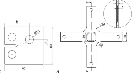
A Compact tension (CT) specimen was modeled according to standard ASTM-E647, with (W) of 50 mm and 8 mm thickness (B). The specimen was modified with a 13 mm diameter hole, placed on variable coordinates a and b (Figure 2 a)). This specimen is similar to the work of Shi et al. (2010). Our goal was to test the algorithm for crack propagation under mixed mode conditions. The hole introduces crack opening mode II on the specimen, and the variable hole position can be used to analyze the conditions where it acts as a sink hole, attracting the crack, or a miss hole, where the crack trajectory is initially attracted by the hole but is then deflected, missing the hole. Four different conditions were tested with our algorithm: a = 15 mm, b = 30 mm; a = 10 mm, b = 30 mm; a = 10 mm, b = 40 mm; and a = 15 mm, b = 40 mm. The modified CT specimen FEA model used three-dimensional quadratic elements with 20 nodes. A total of 77 732 nodes were used to model the specimen. The applied load has a maximum value of 10 kN with R=0.1. The fixating pins were not modeled. Each hole was tied to a reference point on the hole center, and vertical periodic boundary conditions force the vertical displacement of the specimen to be symmetrical. The reference points allow for free rotation on a perpendicular axis to the specimen thickness, while the remaining degrees of freedom were blocked.
2.3. Cruciform Specimen
Cruciform specimens were modeled considering a base material thickness of 3 mm. Each arm of the cruciform specimen has a length of 100 mm and 30 mm width. The radius of curvature between the arms was 20 mm. The thickness on a 30x30 mm square area in the specimen center, was reduced to 1 mm, allowing for fatigue crack propagation using lower applied loads (Figure 2 b)). A symmetric 1 mm notch and 0.25 mm wide was introduced on the specimen center, at 0º or 45º angle with the horizontal arms.
a) b)
Fig. 2. a) Modified CT specimen, a and b hole positioning coordinates; b) Cruciform specimen with center reduced thickness.
This specimen, similar to the one used by Misak et al. (2014) and Misak et al. (2013), allows for in-plane biaxial fatigue crack propagation simulation under different loading conditions. Each of the specimen arms ends were tied to a different reference point. The horizontal arms were only allowed to move in the horizontal direction, while the
vertical arms were only allowed to move in the vertical direction. Periodic boundary conditions were applied to both horizontal and vertical arms, forcing symmetrical displacements. The specimen arms remain bend free, while the specimen center maintains its original position and the crack propagation is not influenced by boundary conditions. The specimen is subjected to horizontal (σxx) and vertical (σyy) nominal stresses:
𝜎𝜎𝑥𝑥𝑥𝑥= 𝜆𝜆 ∙ 𝜎𝜎 ∙ 𝑠𝑠𝑠𝑠𝑠𝑠(2𝜋𝜋 ∙ 𝑡𝑡 + 𝜑𝜑) (8)
𝜎𝜎𝑦𝑦𝑦𝑦= 𝜎𝜎 ∙ 𝑠𝑠𝑠𝑠𝑠𝑠(2𝜋𝜋 ∙ 𝑡𝑡) (9)
Where σ is the nominal stress of 100 MPa, λ is the biaxial load ratio that assumed the values of 0.5, 1.0 and 1.5, and φ the load phase angle that assumed the value of 0º for in-phase loading or 180º for out-of-phase loading.
The specimen was modeled using three-dimensional quadratic elements with 20 nodes on the specimen center, and only 10 nodes on the specimen arms. A total of 107 492 nodes where used on the specimen.
3. Results and Discussion 3.1. Modified CT Specimen
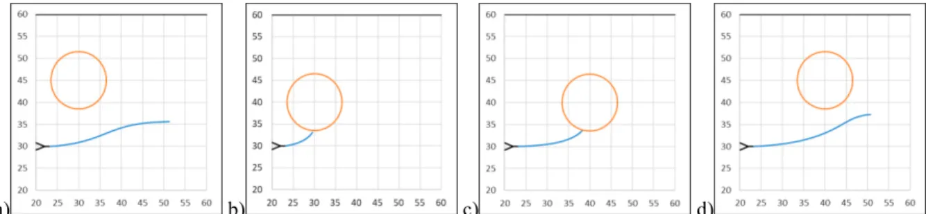
Four different conditions were tested under our algorithm using the modified CT specimen. Our main goal was to assess the algorithm ability to simulate crack propagation under mixed mode conditions. According to Boljanović et al. (2011) this can be done introducing one or several holes in pure mode I specimens. Figure 3 shows the predicted crack propagation trajectories. It is possible to conclude that the introduced hole behaves as a sink hole when the center placement coordinate a is 10 mm. If the hole is placed with a = 15 mm the crack will always miss the hole. As can be seen in Figure 3 a) and d), the crack is initially attracted by the hole, but will miss the hole and its trajectory will tend to return to the horizontal direction. These results are in line with the ones obtained by Shi et al. (2010) or Dirik et al. (2018), using a similar specimen and crack propagation algorithm. Figure 3 b) and c), shows that the crack will always be attracted to the hole, for any hole placement coordinate b. Therefore, it is possible to conclude that the horizontal hole position does not affect the hole behavior. The differentiating factor between hole behaviors seems to be the mode mixity ratio KII/KI. When a = 10 mm, the hole presence increases the mode mixity ratio and
once KII/KI > 0.020 the crack will no longer be able to escape the hole attraction. For a = 15 mm, KII/KI < 0.020, and
the crack although attracted by the hole is still able to escape the hole, missing it. In the case of a = 15 mm and b = 40 mm, KII/KI will eventually be higher than 0.020, but only after the crack has passed the hole and this higher mode
mixity ratio will act in the opposite direction, deflecting the crack back to the horizontal propagating direction. Boljanović et al. (2011) mentioned that the crack increment is one of the most important parameters on the crack propagation simulation process. Different crack increments may lead to the crack missing the hole, even when it behaves as a sink hole. In our simulation an increment of 0.5 mm was used. Different values were tested but the final crack trajectory was only slightly affected, and never missed the holes, when a = 10 mm. A similar analysis was performed by Shi et al. (2010) with similar results.
a) b) c) d)
Fig. 3. Fatigue crack propagation trajectory on modified CT specimen with a) a = 15 mm; b = 30 mm; b) a = 10 mm; b = 30 mm; c) a = 10 mm; b = 40 mm; d) a = 15 mm; b = 40 mm centered hole.
3.2. Cruciform Specimen
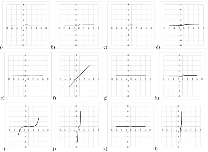
Crack propagation under in-plane biaxial loads have been studied by several authors. While Lee et al. (2011) and Breitbarth et al. (2018) have studied crack propagation under different biaxial load ratios and load phase condition on large specimens, Misak et al. (2014) and Misak et al. (2013) have studied crack propagation on smaller specimens. Our specimen features a reduced center thickness, this allows for lower loads to be applied, maintaining the same crack propagation rates. Using the current geometry the applied load can be up to 44% lower, but future optimization work, similar to the one developed by Baptista et al. (2015), will enable even lower loads and optimal crack propagation paths. Figure 4 shows propagation paths for different simulated conditions. The initial notch orientation, biaxial load ratios λ and load phase φ. For in-phase and horizontal initial notch Figures 3 a), e) and i) show the influence of the biaxial load ratio. For λ = 0.5 and 1.0 the crack propagation direction will remain horizontal. The higher load applied on the vertical direction and the absence of mode II, make this the expected behavior. When λ = 1.5, the higher load applied to the horizontal axis and small numerical variations, that are responsible for small crack propagation deviations, deflects the crack towards the vertical axis (Figure 4 i)). This behavior is also confirmed by Misak et al. (2014).
a) b) c) d)
e) f) g) h)
i) j) k) l)
Fig. 4. Cruciform specimen fatigue crack propagation trajectory for a) β=0º, λ=0.5 and φ=0º; b) β=45º, λ=0.5 and φ=0º; c) β=0º, λ=0.5 and φ=180º; d) β=45º, λ=0.5 and φ=180º;e) β=0º, λ=1.0 and φ=0º; f) β=45º, λ=1.0 and φ=0º; g) β=0º, λ=1.0 and φ=180º; h) β=45º, λ=1.0 and φ=180º;
i) β=0º, λ=1.5 and φ=0º; j) β=45º, λ=1.5 and φ=0º; k) β=0º, λ=1.5 and φ=180º; l) β=45º, λ=1.5 and φ=180º.
Our analysis also included T-stress analysis. As mentioned by Breitbarth et al. (2018) under negative T-stress the crack path remains stable, but under positive T-stress the initial crack path becomes unstable and the crack tends to kink. For the crack in Figure 4 i) T-stress > 0 until a crack length of 6 mm, when the crack propagation direction
increases around 9º by increment. After this point T-stress becomes negative and the crack propagation direction stabilize. When considering an out-of-phase loading, for an initial horizontal crack, Figure 4 c), g) and k) show that the crack propagation direction will always be horizontal, for any λ value. This behavior has been experimentally verified by While Lee et al. (2011), and is justified by the negative T-stress values obtained in our simulations. Figure 4 b), f) and j) show the FCG behavior when in-phase loading conditions are applied to a 45º initial crack. Crack propagation depends on the biaxial load ratio value. For λ = 0.5, under the higher load applied to the vertical axis, the crack will propagate horizontally, while when λ = 1.5, under higher load applied to the horizontal axis, the crack will propagate vertically. This is in line with the results obtained by Misak et al. (2013) and Lee et al. (2011). When λ = 1.0 mode II is absent, and the crack will propagate along the initial 45º direction. Finally, for an out-of-phase loading, Figure 4 d), h) and l) show that if λ = 0.5 or 1.0 the crack will propagate on the horizontal direction, but if λ = 1.5 the crack will propagate on the vertical direction.
On an infinite plate, stress intensity factors for mode I and mode II, can be calculated by Sih et al. (1962): 𝐾𝐾𝐼𝐼 = 𝜎𝜎√𝜋𝜋𝜋𝜋(𝑐𝑐𝑐𝑐𝑐𝑐2𝛽𝛽 + 𝜆𝜆𝑐𝑐𝑠𝑠𝑠𝑠2𝛽𝛽) (10) 𝐾𝐾𝐼𝐼𝐼𝐼 = 𝜎𝜎√𝜋𝜋𝜋𝜋(1 − 𝜆𝜆)𝑐𝑐𝑐𝑐𝑐𝑐𝛽𝛽𝑐𝑐𝑠𝑠𝑠𝑠𝛽𝛽 (11) Using the MTS criterion, initial crack propagating direction can be calculated. Theoretical values for out-of-phase loading and 45º initial crack angle, are -19.2º, -25.5º and 111.8º for λ = 0.5, 1.0 and 1.5 respectively. These values can be compared to the ones obtained with are model, -22.1º, -25.4º and 113.6º, showing that the model is accurately predicting crack propagation even for out-of-phase conditions.
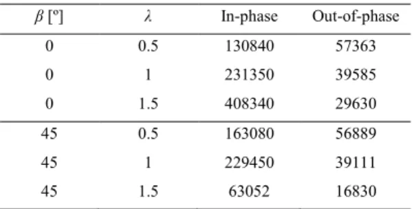
Table 1 shows the obtained results for the corresponding FCG lives. According to Misak et al. (2014) and Misak et al. (2013) the FCG life is inversely proportional to λ when the initial crack angle in 0º. This behavior was verified by our work, therefore for λ = 1.5 the crack propagation rate is low, and the obtained fatigue life is higher. When the initial crack angle is 45º the slower crack propagation rate occurs for λ = 1.0, followed by λ = 0.5 and 1.5. This behavior was also verified by Misak et al. (2013). Finally, as verified by Lee et al. (2011) when out-of-phase loading conditions are applied, our algorithm predicts that the crack propagation rate is proportional to the biaxial load ratio and is crack initial angle independent.
Table 1. Total fatigue crack propagation lives for different conditions.
β [º] λ In-phase Out-of-phase 0 0.5 130840 57363 0 1 231350 39585 0 1.5 408340 29630 45 0.5 163080 56889 45 1 229450 39111 45 1.5 63052 16830 4. Conclusions
Using a previously developed automatic fatigue crack propagation algorithm for mode I dominated cases, the necessary modifications were done to simulate mixed mode fatigue crack propagation. A modular structure, using
Matlab to initiate the simulation and calculate the fatigue propagation life and path, Python to update the FEA
model, and Abaqus to calculate the fracture mechanics parameters, was considered viable. The algorithm was tested with a modified CT specimen, where a variable positioned hole introduced a mixed mode propagation environment. The crack path was accurately predicted when compared with different experimental and numerical solutions. It was also determined that the hole vertical coordinate influences the hole behavior, attracting or only deflecting the crack path, while the hole horizontal location does not affect the sink or miss hole behavior. A cruciform specimen, with reduced central thickness, was developed, enabling lower applied loads for the same crack propagation rates. Different biaxial load rates were applied with in or out-of-phase loading conditions, to two initial crack angles. The obtained fatigue crack paths are in good agreement with experimental and numerical results obtained by several
authors. Crack propagation rates were correctly predicted. It was also verified that negative T-stress stabilize crack direction, while positive T-stress lead to crack kinking. The algorithm is therefore able to predict fatigue crack propagation even for complex loading conditions.
Acknowledgements
This work was supported by FCT, through IDMEC, under LAETA, project UID/EMS/50022/2019.
References
Armentani, E., R. Citarella, and R. Sepe. (2011). “FML Full Scale Aeronautic Panel under Multiaxial Fatigue: Experimental Test and DBEM Simulation.” Engineering Fracture Mechanics 78(8):1717–28.
Baptista, R., R. A. Claudio, L. Reis, J. F. A. Madeira, I. Guelho, and M. Freitas. (2015). “Optimization of Cruciform Specimens for Biaxial Fatigue Loading with Direct Multi Search.” Theoretical and Applied Fracture Mechanics 80:65–72.
Baptista, Ricardo, Virginia Infante, and João Marques. (2019). “Algorithm for Automatic Fatigue Crack Growth Simulation on Welded High Strength Steels.” Frattura Ed Integrità Strutturale 13(48):257–68.
Boljanović, Slobodanka and Stevan Maksimović. (2011). “Analysis of the Crack Growth Propagation Process under Mixed-Mode Loading.”
Engineering Fracture Mechanics 78(8):1565–76.
Breitbarth, Eric and Michael Besel. (2018). “Fatigue Crack Deflection in Cruciform Specimens Subjected to Biaxial Loading Conditions.”
International Journal of Fatigue 113:345–50.
Dhondt, Guido. (2014). “Application of the Finite Element Method to Mixed-Mode Cyclic Crack Propagation Calculations in Specimens.”
International Journal of Fatigue 58:2–11.
Dirik, Haydar and Tuncay Yalçinkaya. (2018). “Crack Path and Life Prediction under Mixed Mode Cyclic Variable Amplitude Loading through XFEM.” International Journal of Fatigue 114(October 2017):34–50.
Erdogan, F. and G. C. Sih. (1963). “On the Crack Extension in Plates Under Plane Loading and Transverse Shear.” Journal of Basic Engineering 85(4):519.
Lee, E. U. and R. E. Taylor. (2011). “Fatigue Behavior of Aluminum Alloys under Biaxial Loading.” Engineering Fracture Mechanics 78(8):1555–64.
Misak, H. E., V. Y. Perel, V. Sabelkin, and S. Mall. (2013). “Crack Growth Behavior of 7075-T6 under Biaxial Tension-Tension Fatigue.”
International Journal of Fatigue 55:158–65.
Misak, H. E., V. Y. Perel, V. Sabelkin, and S. Mall. (2014). “Biaxial Tension-Tension Fatigue Crack Growth Behavior of 2024-T3 under Ambient Air and Salt Water Environments.” Engineering Fracture Mechanics 118:83–97.
Nasri, Khalid and Mohammed Zenasni. (2017). “Fatigue Crack Growth Simulation in Coated Materials Using X-FEM.” Comptes Rendus -
Mecanique 345(4):271–80.
Paris, PC and F. Erdogan. (1963). “A Critical Analysis of Crack Propagation Laws.” Journal of Basic Engineering 85(4):528–33. Qian, J. and A. Fatemi. (1996). “MIXED MODE FATIGUE CRACK GROWTH: A LITERATURE SURVEY.” Engineering Fracture
Mechanics 55(6):969–90.
Rabold, F. and M. Kuna. (2014). “Automated Finite Element Simulation of Fatigue Crack Growth in Three-Dimensional Structures with the Software System ProCrack.” Procedia Materials Science 3:1099–1104.
Shi, Jianxu, David Chopp, Jim Lua, N. Sukumar, and Ted Belytschko. (2010). “Abaqus Implementation of Extended Finite Element Method Using a Level Set Representation for Three-Dimensional Fatigue Crack Growth and Life Predictions.” Engineering Fracture Mechanics 77(14):2840–63.
Sih, G. C., P. C. Paris, and F. Erdogan. (1962). “Crack-Tip, Stress-Intensity Factors for Plane Extension and Plate Bending Problems.” Journal of
Applied Mechanics 29(2):306.
Xiangqiao, Yan, Du Shanyi, and Zhang Zehua. (1992). “Mixed-Mode Fatigue Crack Growth Prediction in Biaxially Stretched Sheets.”
Engineering Fracture Mechanics 43(3):471–75.
Yang, Ying and Michael Vormwald. (2017). “Fatigue Crack Growth Simulation under Cyclic Non-Proportional Mixed Mode Loading.”
International Journal of Fatigue 102:37–47.
Yu, Xiaobo, Ling Li, and Gwénaëlle Proust. (2017). “Fatigue Crack Growth of Aluminium Alloy 7075-T651 under Proportional and Non-Proportional Mixed Mode I and II Loads.” Engineering Fracture Mechanics 174:155–67.