167
Ivan Julio Apolonio Callejas
Professor - Doutor
Universidade Federal de Mato Grosso - UFMT Departamento de Arquitetura e Urbanismo Cuiabá - Mato Grosso - Brasil
Luciane Cleonice Durante
Professora - Doutora
Universidade Federal de Mato Grosso - UFMT Departamento de Arquitetura e Urbanismo Cuiabá - Mato Grosso - Brasil
Angela Santana de Oliveira
Professora - Doutora
Instituto Federal do Mato Grosso – UFMT Departamento de Construção Civil Cuiabá - Mato Grosso - Brasil [email protected]
Thermal resistance and
conductivity of recycled
construction and demolition
waste (RCDW) concrete blocks
Abstract
In Brazil, studies to reuse construction and demolition waste are a special issue because a large amount of this material has been delivered to the public landills and in illegal places. Some researchers have suggested reusing this material in building elements, such as bricks or blocks. It is possible to ind a lot of researches in physical/ mechanical characterization, while little effort has been made to characterize recycled construction and demolition waste blocks (RCDW) for their thermal properties. The aim of this work was to characterize the RCDW thermal resistance and conductivity in order to provide subsidies for a building’s thermal performance analysis. The hot-box method was adapted, together with measuring techniques with a heat-low meter to determine the RCDW thermal properties. The results indicated that the RCDW block overall thermal resistance and thermal conductivity in the solid region was within the intervals of 0.33≤RT≤0.41m2KW-1 and 0.60≤λ≤0.78Wm-1K-1, respectively. The lower
resistance and conductivity values are justiied by the presence of aggregate with a lower density and lower thermal conductivity than the natural aggregate.
Keywords: hot-box method, sustainable materials, thermal properties.
http://dx.doi.org/10.1590/0370-44672015700048
Civil Engineering
Engenharia Civil
1. Introduction
A large amount of construction and demolition (C&D) waste (known as C&D materials or C&D debris) are generated in cities around the world. C&D wastes, such as bricks, ceramic bricks, concrete, soil, wood, among others, are produced when new struc-tures are built, when existing strucstruc-tures are renovated or demolished, and when the land is prepared or excavated (ABNT, 2004). Construction and de-molition waste management has been a major issue worldwide due to the high level of construction activity in economically advanced countries and in emerging economies such as Brazil and China (Agamuthu, 2008). In Brazil, one third of this material is delivered to the public landills, while the rest is generally disposed of in illegal places (Leite et al., 2011).
The inert fraction of demolition waste, usually derived from concrete, bricks and tiles, is well suited to be
recycled as a substitute for coarse ag-gregate. It has a great potential to be reused in building elements, like bricks, blocks, and in road construction, for bases and sub-bases (Leite et al., 2011;
Soutsos et al., 2011). Some researchers
have veriied that the replacement of the course and ine natural aggregates, by recycled aggregates at the levels of 25 and 50%, have little effect on the compressive strength, although higher levels of replacement reduced the com-pressive strength (Soutsos et al., 2011;
Leiva, et al., 2013). So, the aggregate
derived from recycled construction and demolition waste (RCDW) is an attrac-tive alternaattrac-tive material to be utilized in new constructions. In the references, it is possible to ind a lot of research in physical and mechanical characteriza-tion of these materials but little effort has been made in characterizing the thermal properties of RCDW blocks (thermal resistance/transmittance and
The thermal resistance property is directly dependent on the material type, thickness and density of each layer present in the wall and roof composi-tion. For most wall and roof patterns, the theoretical thermal resistance can be obtained in manufacturer catalogs or can be estimated by procedures es-tablished in standard codes (ISO 6946, 1997; ABNT, 2003). In the calculation model, it is usually necessary to previ-ously know the geometrical, density and conductibility of the wall or roof components. The R-values obtained are especially used in the building design. However, theoretical values differ from the R-value determined by in-situ methods. Uncertainties in material properties, in mathemati-cal model, in the modiication of the inal thickness layers during the wall/ roof execution process, among others, cause differences between the models. The calculation model cannot be ap-plied in cases in which these previous properties are unknown, specially the thermal conductivity coeficient. This usually happens in blocks in which the aggregate was obtained from RCDW. It is usual to make physical and me-chanical characterization of RCDW blocks, restricting the determination of R-values by in situ tests.
Literature presents two meth-ods to determine the in situ thermal insulation of buildings: steady-state and transient (dynamic) measurement techniques (Incropera, 2007). The steady-state measurement technique is based on a one-dimensional heat low approach and requires a temperature gradient over a known thickness of
the sample. The temperature must be established in order to control the heat low between the two sides of the tested element. The R-value can easily be obtained by measuring the gradient temperature together with direct heat-lux through the sample. Three main techniques are applied: the guarded hot-plate, the hot-box technique and the heat-low meter.
The hot-box, applied in this study, consists of a ive-sided box mounted in the warm side of the room with the open side enclosing the test sample. The heat input to the box is controlled so that the temperature in the box is the same as in the surrounding warm room (ABNT, 1980; ISO 8990, 1994). However the heat-low meter method is usually applied to test the insulation parameters of building envelopes in situ because of its lightweight components and matching parts (ISO 8301, 1991; ISO 9869, 1994). However, with in situ thermal analyses, the experimental determination of the thermal resistance of walls always presents practical problems, especially, in finding the steady state conditions across it. It is practically impossible to control the thermal transient because of the daily variation of climatic conditions. An-other possibility is to make prototype experiments, but the costs are high because it is necessary to manufacture the prototype, transport it and install it in the laboratory. Because of the differ-ences in the prototype wall fabrication and the in situ thermal analyses of the walls, along with the differences in the experimental conditions (one is made under a laboratory-controlled climate
and the other placed within a natural actual climate), the thermal resistance of the wall determined in situ might present a signiicant deviation from the resistance determined from the prototype. The difference between experimental results and theoretical values is greater when compared to the hot-box technique (more accurate) be-cause thermal properties are dependent on climatic effects including humidity and solar radiation, among others (Peng and Wu, 2008; Luo et al., 2011).
As RCDW blocks can be con-sidered new or alternative material to be used in new constructions, in situ thermal experiments should be discarded in order not to compromise the building thermal performance. The prototype experiment should also be abandoned because of the necessity of the large amount of samples that have to be manufactured, which involves high initial costs in the experiment. Therefore, the hot-box technique seems to be the best choice.
This paper aimed to characterize the thermal resistance and thermal conductivity of RCDW blocks. To do this, the hot-box chamber adapted, along with measuring techniques from the heat-flow meter to perform the thermal insulation by RCDW blocks. These properties are very important for performing a building’s thermal energy simulation and are not presented in the Brazilian Code NBR 15220 (ABNT, 2003). Notwithstanding, this search complements a previous study denomi-nated “Constructive Techniques with Sustainable Practices” developed by Santos et al. (2013).
2. Materials and methods
2.1 Materials
The construction and demolition (C&D) waste utilized in this work was initially pre-screened, classiied and un-derwent manual triage. It was deined as just mortar, concrete and clay brick for its composition. The selected material underwent crushing and screening pro-cesses, whereby three types of recycled aggregates were obtained, which were classiied according to the particle sizes (or sieve size): 4.74 (#4), 2.0 (#10), 0.425 (#40) and 0.075 (#200)mm. Samples were screened out in the initial stage using a #4 sieve. Recycled Fine Particles (RFP) were classiied by the particle size
smaller than the mesh of #4 sieve and Re-cycled Coarse Particles (RCP) remaining in the sieve (Figure 1a). In the concrete preparation, only the fraction passing the #4 sieve was used and that remain-ing in the mesh #200 sieve (RFP), plus Pozzolanic Portland Cement (PC IV 32).
After RCDW classiication into different particle sizes, the Theoretical Experimental Packaging adapted by Costa (2006) was performed. Mixed were three size fractions in different percentages, in order to determine the combination for a higher bulk density and lower voids in the concrete mixture.
169
(a) (b)
Figure 1 (a) Classified construction
and demolition waste and (b) RCDW Blocks (250x125x75mm).
2.2 Blocks Manufacturing
The block’s composition was ob-tained by completely replacing the ine aggregate with recycled FP. The dry components (cement and recycled pow-der, sand and ine gravel) were placed in a planetary mixer until a homogeneous combination was obtained. Water was then added to obtain a homogeneous paste. The formed paste was placed
into molds for manufactured samples of various shapes and sizes to be used in the physical, mechanical and thermal tests (Figure 1b). Samples were taken out of the molds 24 hours after casting and cured in a water tank at 25°C for 28 days. The compressive strength tests were performed at ages 7 and 28 days (ABNT, 1995). The compressive strength was
superior to 4MPa, and the bricks were classiied as Class B for structural use in wall elements just above the ground level. The physical tests indicated that there was saturated speciic mass, dry speciic mass, voids ratio and water absorption by dipping was 1.6gcm-3, 1.48gcm-3,
26.75% and 12.5%, respectively (Santos
et al., 2013).
2.3 Chambers Manufacturing
2.4. System Test
The RCDW thermal resistance test followed the adapted hot-box technique, according to NBR 6488 (ABNT, 1980). The heat lux between hot and cold box was estimated using a thermal luximeter (ISO 9869, 1994). The first chamber (denominated “hot chamber”) was com-posed of a sandwich panel made of MDF wood boards (16mm), EPS boards (50 mm) and thin aluminum foil to isolate it from the exterior climate. One infrared lamp (250W) was positioned inside the
chamber for an internal heat source and a dimmer dispositive was utilized to adjust the infrared light level.
The second chamber (denominated “ambient chamber”) was composed of just EPS boards (25mm) to help stabilize the external temperature, making the heat luxes less dependent on external weather conditions and improving the thermal steady-state conditions between the two chambers. It is not a cold chamber because refrigeration was not used to cool
the air inside the ambient as prescribed by Brazilian code NBR 6488 (ABNT, 1980). This chamber was just kept at room tem-perature with the objective of isolating the sample from direct climatic conditions. The samples were attached in the cham-ber in order to be exposed to the hot air generated by the heat/radiation emitted from the infrared light and were protected from direct radiation. They were heated indirectly by hot air circulation inside the chamber with the help of three fans.
To estimate the heat lux between the hot and ambient chambers, the heat-lux meter technique (ISO 9869, 1994) was used. The walls to be tested were instrumented by thermistor NTC with
10k sensors (accuracy of ±0.25°C) for the surface temperature measurement. Two sensors were installed in the central position of the wall sample, facing the interior of the hot chamber. The
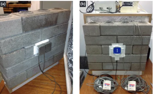
sen-sors were adequately protected from the movement of hot air inside the hot cham-ber (Figure 2a) and ixed with adhesive tape. Another two sensors were ixed on the exterior center of the sample’s wall,
Figure 2 (a) Internal and (b) external temperature and heat flux sensor in the RCDW wall.
facing the ambient chamber. They were positioned between the heat-lux sen-sors (near the circular plate), installed in the vertical position and ixed adhesive tape, to avoid direct contact with the air. A heat-lux sensor, model HFP01 manufactured by Hukselux (accuracy of 5% on sample wall), was ixed to
the exterior face of the sample’s wall between the two temperature sensors to measure the heat-lux. It was ixed using adhesive tape in all its contours (Figure 2b) and its central position was facing the opposite direction of the interior tem-perature sensor. A good thermal contact between all sensors and the sample wall
surface was ensured. All the sensors were connected to a data logger to perform the automatic readings. A sample rate measurement of 5 minutes was chosen to be adequate, taking into account the variation velocity of the environmental parameters measured. All the equipment was previously calibrated.
2.5 Test wall thermal resistance calculation
Measurement analysis was carried out with the progressive mean method as stipulated by ISO 9869 (1994). R-value
can be calculated by Equation 1, where
Tsi is the internal temperature, Tse is the
ex-ternal temperature, q is heat low between
the two sides of the tested element and j
represents each measurement made during the element test.
R
n=
n
j = 1
(
Tsij - Tsej
)
nj = 1
q
j(1)
(2)
The Rn calculation for each
mea-surement is made in succession, start-ing from the irst. The calculated value converges asymptotically to the real value (especially thermal steady-state conditions). The R-value of sample’s wall was evaluated using the mean of temperatures and heat-low rates, at least in a period of temperature wave
(such as 1 day, 24h) instead of the im-mediate data.
To verify the adaptation of the hot-box method, a material with thermal resistance known previously (Wood Wool Cement Board - WWCB) was tested and the results were very close to its theoretical thermal resistance.
With the chamber tested, two
RCDW sample walls with dimensions of 0.50x0.375x0.125m (Figure 2) were tested in the solid face and in the region where there was an air gap. The air gaps were closed on the upper surface of the blocks aiming to adequately represent the behavior of the wall in service. The measurements were carried out during at least 72h (3 days).
2.6. Error Analysis
The uncertainty of the R-value
es-timate was derived from the individual measurement uncertainties and the Stan-dard Deviation (S.D.) of the average value.
This is necessary because each of the mea-sured parameters (heat lux, internal and external temperature) has an associated uncertainty due to the sensor itself and
be-cause of the logging system (Baker, 2011). The error determination of each variable measured on the R-value was estimated
with each measured parameter disturbed by its error. The instrument’s calibration error declared by the manufacturers was assumed. The overall uncertainty on the
R-value estimation (δRn) can be
calcu-lated as the Root Mean Square (RMS) value of the deviations of each error case from the base case plus the S.D. of the Rn average period considered (Equation
2), where Rerr_Tsi, Rerr_Tse and Rerr_Q, are the R-values calculated by applying the
er-rors due to internal/ external tempera-ture and heat lux.
R
n- R
err_Tsi+
R
n- R
err_Tse+ R
n- R
err_Q+ S.D.
δ
R
n=
2 2 2 2
As the R-value calculated converges
asymptotically to the inal value of Rn
and as we were only interested in the inal average value, the combined uncer-tainty was evaluated only in the period
of the last temperature wave experi-ment (last 24hours). The measureexperi-ment of the statistical uncertainty (expanded uncertainty) can be taken into account assuming a coverage factor (k) equal to
2, which is the typical value in this kind of measurements. This coverage factor leads to a conidence level of approxi-mately 95% (Baker, 2011). The inal
R-value can be expressed by Equation 3.
R = Rn± k.δRn (3)
3. Results and discussion
The irst test was conducted in the block’s solid face. The test was carried out during three and a half days as presented in the Figure 3. It is possible to notice that the calculated value converges asymptotically with the real value, as desired. The surface
temperature difference between the two faces of the sample (∼13.4°C) was not high because RCDW blocks are not considered good isolators (Table 1). The mean heat lux through the block was 76Wm-2. R
n oscillates until it settles
and the oscillation has low amplitude
because of the good constancy of the temperature difference established, remaining near 6.35% (Figure 3a). The
R-value estimated and the error analysis
171
Table 1 Rn value estimation of RCDW wall 1: (a) in the solid face and (b) in the face with air void.
Sensor position (a) Solid face (b) Face with air void
Variables average values (24hours)
Difference temperature 13.41°C 12.81°C
Internal Surface Temperature 55.88°C 55.33°C
External Surface Temperature 42.47°C 42.53°C
Heat flux 76.35 Wm-2 66.93Wm-2
Average Rn-value 0.18m2KW-1 0.19m2KW-1
Overall uncertainty δRn 0.01m2KW-1 0.01m2KW-1
Error analysis
Rerr_Tsi (sensor error 0.25°C) 0.18 m2KW-1 0.2 m2KW-1
Rerr_Tse (sensor error 0.25°C) 0.18 m2KW-1 0.2 m2KW-1
Rerr_Q (5% heat flux) 0.18 m2KW-1 0.2 m2KW-1
standard derivation (S.D.) 0.004m2KW-1 0.002m2KW-1
Percentage error 6.35% 6.05%
Tsi Tse R1 (Solid face) Tsi Tse R1 (air void)
Sur
face t
emper
atur
e (
0C)
Period of time (days)
Thermal Resist
ance (m
2 K/W)
Sur
face t
emper
atur
e (
0C)
Period of time (days)
Thermal Resist
ance (m
2 K/W) 60
50
40
30
20
10
0
0 1 2 3
0.5
0.3
0.2
0.0
60
50
40
30
20
10
0
0 1 2 3
0.5
0.3
0.2
0.0
Figure 3 Internal and external surface temperature in the wall experi-ment and thermal resistance in (a) solid surface and (b) in the face with air void.
Another test was performed with the sensor installed in the face of the sample where there is a presence of an internal air void (Figure 3b). The internal and ex-ternal surface temperatures were similar to that observed in the irst test (Table 1), but the heat lux was 9.5Wm-2 lower than
the heat lux observed in the solid region of the wall. The behavior was attributed to the presence of the unventilated air layer within the wall (thickness layer higher than 25mm) which has a similar thermal resistance design value to that of the concrete blocks made of RCDW (Rairlayer=0.18m2KW-1) (ISO 6946, 2008;
ABNT, 2003). The estimated R1-value
and the error analysis is presented in the Table 1 and the mean R1-values and the
uncertainties for the measurement test was 0.19m2KW-1±0.02m2KW-1.
The experiments were repeated in one more RCDW sample. The results were similar to the irst with small differences in the internal and external temperature and in heat lux through the wall. The mean R2-values were similar and the
uncertainties for the measurement ex-periments in solid and in internal air void position were 0.19m2KW-1±0.02m2KW-1
and 0.21m2KW-1±0.02m2KW-1,
respec-tively. The observed differences were only 0.02m2KW-1 between the experiments.
For a concrete with density between 1600-2100kgm-3 (density near the RCDW
blocks), the thermal conductivity was equal to 1.40Wm-1K-1 (ABNT, 2003),
and thermal resistance was equal to 0.09m2KW-1. This value is lower than the
RCDW blocks in the solid region. The overall thermal resistance of the block was calculated weighing the ther-mal resistance obtained in the two experi-ments in the solid and air void region by its respective areas in the cross section of the block (ABNT, 2003). The R1-value and R2-value of overall thermal resistance were
0 . 18 m2K W- 1± 0 . 0 2 m2K W- 1 a n d
0 . 2 0 m2K W-1± 0 . 0 2 m2K W-1. T h e
con f idenc e i nter va l was s e t at 0.16≤RT≤0.22m2KW-1. The total
ther-mal resistance was determined using the procedures established by NBR 15220 (ABNT, 2003), by adding the internal and external surface resistances to the overall thermal resistance of the block, which led to 0.35m2KW-1±0.02m2KW-1
and 0.37m2KW-1±0.02m2KW-1,
respec-tively. The conidence interval was set at
0.33≤RT≤0.39m2KW-1.
The RCDW concrete conductiv-ity (inferior, mean and superior λ-value) was determined by dividing the block thickness by its thermal resistance in the solid region. Following this procedure for the first and the second experi-ment, the conidence interval was set at 0.60≤λ≤0.78Wm-1K-1. It is expected that
RCDW concrete would display lower values of thermal conductivity than the conventional concrete not only due to the presence of aggregate with a lower density and lower thermal conductivity (like ceramic brick and gypsum) than the natural aggregate, but also due to the higher porosity observed in mixture. Leiva et al. (2012) tested RCWD and
con-ventional concrete blocks and determined 0.66Wm-1K-1 and 1.63Wm-1K-1 of thermal
conductivity, respectively.
The total thermal resistance of the RCDW wall was inferior to the usual Bra-zilian construction wall made of external and internal mortar and ceramics blocks with internal voids (thermal resistance varying from 0.4 to 0.45m2KW-1). NBR
15220 (ABNT, 2003) divided Brazil into eight bioclimatic regions and depending on
the building’s region of installation, it stated that for exterior walls with absorptance superior 0.6, the walls must have a total transmittance lower than 2.50Wm-2K-1 in
order to avoid excessive heat gain. The transmittance of the RCDW wall can be obtained inverting the total thermal
resistance determined (U=1/R = 2.57 and 3.03Wm-2K-1). RCDW blocks are made
of cement and their inal color is clay. Thus, the absorptance is higher than 0.6. Thereby, RCDW walls were not indicated to be used in some Brazilian bioclimatic regions. It was suggested that the
ex-ternal wall be painted with light colors (absorptance lower than 0.6) to attend the Brazilian code. Another possibility was to introduce internal/external mortar (0.025m) in the RCDW wall to reduce the thermal resistance to 0.4m2KW-1, a value
close to the usual Brazilian wall.
4. Conclusions
The adapted methodology was able to determine the thermal resistance of an RCDW wall and the following conclusions can be stated:
(a) The block’s overall thermal resis-tance was set at 0.33≤RT≤0.39m2KW-1,
inferior to traditional ceramic blocks with mortar, utilized in Brazilian struction walls; (b) The RCDW con-crete thermal conductivity varies from 0.60≤λ≤0.78Wm-1K-1, which is lower
than the 1.40 Wm-1K-1 presented in NBR
15220 (ABNT, 2003) because recycled material has lower thermal conductivity than natural aggregate; (c) It was neces-sary to paint the external wall with light colors to attend the thermal transmittance stipulated in the Brazilian code; this pro-cedure makes it possible to use RCDW blocks as a building component; therefore, it is an alternative material to reduce the delivery of construction and demolition waste to the public landills and to illegal places; (d) The chamber utilized helped
to improve building thermal performance because it allowed modiications to be introduced in the building design phase; it permits the determination of the R-value of a building envelope with material that will be used in the region of implantation, which leads to a more realistic thermal insulation for the building envelope than values stipulated in codes; and (e) In con-trast, the chamber has the disadvantages of measuring thermal properties under laboratory-controlled climate.
References
AGAMUTHU, P. Challenges in sustainable management of construction and demoli-tion waste. Waste Management and Research, v. 26, p. 491–492, 2008.
BAKER, P. U-values and traditional buildings. In situ measurements and their
comparisons to calculated values. Scotland: Glasgow Caledonian University,
2011.70p. (Technical Paper 10).
BRAZILIAN ASSOCIATION OF TECHNICAL STANDARDS (ABNT). NBR 6488: Building components - Determination of thermal transmittance and conduc-tance- Hot Box Method. Rio de Janeiro: 1980.
BRAZILIAN ASSOCIATION OF TECHNICAL STANDARDS (ABNT). NBR 6136: Plain concrete hollow block for reinforced masonry – Speciication. Rio de Janeiro: 1995.
BRAZILIAN ASSOCIATION OF TECHNICAL STANDARDS (ABNT). NBR 15220: Thermal performance in buildings – Part 1, 2, 3 and 4. Rio de Janeiro: 2003.
BRAZILIAN ASSOCIATION OF TECHNICAL STANDARDS (ABNT). NBR 15116: Recycled aggregate of solid residue for building constructions - Require-ments and methodologies. Rio de Janeiro: 2004.
COSTA, J.S. Alternative aggregates to mortar and concrete fabricated of recycled vir-gin tailings from traditional ceramic industry. São Carlos, UFSC, 2006 (Thesis). INCROPERA, F.P., DEWITT, D. P., BERGMAN, T. L., LAVINE, A. S.
Fundamen-tals of heat and mass transfer. 6th ed. LTC: John Wiley & Sons, , 2007. 998p. ISO 8301, Thermal insulation - determination of steady-state thermal resistance and
related properties–heat low meter apparatus. International Organization for Stan-dardization, 1991.
ISO 9869, Thermal insulation - Building elements – In–situ measurement of thermal resistance and thermal transmittance. International Organization for Standardiza-tion, 1994.
ISO 8990, Thermal insulation - Determination of steady-state thermal transmission properties - Calibrated and guarded. International Organization for Standardiza-tion, 1994.
ISO 6946, Building components and building elements - thermal resistance and ther-mal transmittance – calculation method. International Organization for Standar-dization, 2008.
LEITE, F.C., MOTTA, R.S., VASCONCELOS, K.L., BERNUCCI, L. Laboratory evaluation of recycled construction and demolition waste for pavements.
173
LEIVA, C., SOLÍS-GUZMÁN. J., MARRERO, M., ARENAS, C. G. Recycled blo-cks with improved sound and ire insulation containing construction and demoli-tion waste. Waste Management, v. 33, p. 663–671, 2013.
LUO, C., MOGHTADERI, B., HANDS, S., PAGE, A. Determining the thermal ca-pacitance, conductivity and the convective heat transfer coeficient of a brick wall by annually monitored temperatures and total heat luxes. Energy and Buildings, v. 43, p. 379–385, 2011.
PENG, C., WU, Z. In situ measuring and evaluating the thermal resistance of building construction. Energy and Buildings, v. 40, p. 2076–2082, 2008.
SANTOS J., SANTOS, M.S.H., ALBUQUERQUE, A.C. Ensaios tecnológicos em ti-jolos provenientes de resíduos de construção e demolição – RCD’s (Technological testing in bricks made of recycled construction and demolition waste - RCDW). In: CONCRETE BRAZILIAN CONGRESS, 55. Annals... Gramado: IBRACON, 2013.
SOUTSOS, M.N., TANG, K., MILLARD, S.G. Concrete building blocks made with recycled demolition aggregate. Construction and Building Materials, v. 25, p. 726–735, 2011.