421
Abstract
This work aims to reduce the energy consumption and thus increase the availabil-ity of blast furnace compressors of a steelmaking company, located in Alto Paraopeba region in Minas Gerais state, Brazil, through the elimination of waste points in the compressed air distribution. In order to develop this work, an ultrasound test in the compressed air line was performed to identify and quantify leaks in the low. Once the leaks were identiied, they were eliminated through corrective maintenance and improvements, and then the energy consumption scenarios before and after the im-provements were compared. As a result, the average monthly electricity consumption in the reporting period decreased by 57.2%. In addition, one compressor was set aside in stand-by condition, as in the original plant. Thus, one can prove the eficiency in eliminating of waste points in compressed air distribution, since the reduction of energy consumption is important for the company to remain competitive, as the cost of electric energy affects the inal price of the inal products.
keywords: compressed air, compressor, energy eficiency, ultrasound test, leaks. Washington Luís Vieira Silva
Professor
Universidade Federal de Ouro Preto – UFOP Escola de Minas
Departamento de Engenharia de Controle e Automação e Técnicas Fundamentais Ouro Preto - Minas Gerais - Brasil [email protected]
Leonardo Carvalho Oliveira Souza Professor
Universidade Federal de Ouro Preto – UFOP Escola de Minas
Departamento de Engenharia de Controle e Automação e Técnicas Fundamentais Ouro Preto - Minas Gerais - Brasil [email protected]
Luís Antônio Bortolaia Professor
Universidade Federal de Ouro Preto – UFOP Escola de Minas
Departamento de Engenharia de Controle e Automação e Técnicas Fundamentais Ouro Preto - Minas Gerais - Brasil [email protected]
Milton Realino de Paula Professor
Universidade Federal de Ouro Preto – UFOP Escola de Minas
Departamento de Engenharia de Controle e Automação e Técnicas Fundamentais Ouro Preto - Minas Gerais - Brasil [email protected]
Elisângela Martins Leal Professora
Universidade Federal de Ouro Preto – UFOP Escola de Minas
Departamento de Engenharia de Controle e Automação e Técnicas Fundamentais Ouro Preto - Minas Gerais - Brasil [email protected]
Study of the electricity
consumption reduction of
a compressed air system: the
case of a steelmaking company
Mechanic and Energy
Mecânica e Energia
1. Introduction
Humankind has been using com-pressed air since its existence for the simple act of blowing a brazier to light a lame. Lungs may be considered compressors, since they are able to process 100 L/min or 6 m³/h of air, using a pressure from 0.02 to 0.08 bar (Atlas Copco, 1976). Through this simple example, the importance of the compressed air use to humanity is demonstrated.
Currently, compressed air deliver-ies power to a wide variety of industrial operations, comprising of small plants to heavy industry, being used in virtually all stages of production.
A generic pneumatic system can be divided into three parts: generation, distri-bution and end use. Rocha and Monteiro (2005) characterized each one as: (i) gener-ation unit includes the compressor driven by an electrical motor (which captures the gas and increases its pressure), automation and control, air handling equipment, tank and accessories; (ii) distribution unit takes the compressed air from the reservoirs to the end use, ensuring that this air reaches the optimal quantity and pressure free of water and impurities; (iii) at the end use unit, the application is varied, for example, to drive pneumatic tools and camshafts.
Electrical energy is consumed for the generation of compressed air. According to Rocha and Monteiro (2005), compressed air is one of the most expensive energy forms in an industrial plant, with the larg-est expenditures in electricity consump-tion, which may represent 30% or more of the total electricity consumed.
Thus, with the increasing market competitiveness, companies have continu-ally sought to reduce operating costs to keep their products at competitive prices, ensur-ing the satisfaction of their customers and shareholders. It is important, therefore, to make conscious compressed air consump-tion in order to avoid unnecessary costs.
According to Beyene apud Raduenz et al. (2009), the main cause of waste in
pneu-matic systems is leaks. Rocha and Monteiro (2005) state that these leaks can represent in industrial compressed air systems without maintenance, 10 to 40% of the maximum compressed air demand, being the admitted value for losses of up to 10% for steelmak-ing industries (Macintyre, 1996).
In order to avoid the compressed air depletion through leaks, the maintenance of all compressed air distribution is necessary. According to Xenos (2004), maintenance activities prevent degradation of equipment
and facilities caused by their use, wear and tear. This fact generates losses of perfor-mance and production downtime, besides of the manufacture of poor quality products and environmental pollution.
One of the biggest uses of compressed air in industry is the manufacture of iron and steel. It takes approximately 3,000 cubic meters of compressed air to produce 1 ton of steel. Rollins (2004) highlights some applications for compressed air: “Compressed air is used in the iron and steel industry for many purposes in addi-tion to the basic process, mainly as a drive force from the functional equipment and tool. These applications include deburring and grinding ingots, trigger hoists and lifts, shake solutions, blast and caulk tanks. They also include the operation of ma-chines to punch, carvings, oven doors, in-strumentation and process control, dumper ingots, drive bell of a blast furnace and coke gates, lubrication systems, clutches and pneumatic brakes, mixing materials, descaling, pneumatic clamps, etc.
In this context, the compressed air system of a steelmaking company is studied. The steelmaking plant has 169 air, argon and nitrogen compressors. The compressors are from Ingersoll Rand, Atlas Copco, Chicago, Sullair, and Worthington and Wayne, all driven by electric motors, with power ranging from 5 to 500 kW. Because of the plant size, several compressed air centrals are located in each production area, among them the blast furnace one.
According to the company (2013), the blast furnace production area is responsible for delivering molten metal, having an installed production capacity of 1.5 million of tons per year. It has three compressors from Atlas Copco; model GA315W with rated power of 271 kW. Each compressor at full load is able to deliver about 2790 m³/h of compressed air with an average pressure of 7.4 bar (7400 kPa) for the production process.
The target area of the study has three compressors; one should work full time, the other one as charge and relief, and the last one as stand-by, only triggered in the event of temporary need. This was the initial plan for the area. However, in practice, one compressor works full time and the other two compressors works in charge and relief to meet the demand. Taking the question of availability into account, in case of stopping one of the
ma-chines for maintenance, the compressed air delivery is compromised. In parallel, the overloaded operation of the system raises the costs of electricity, raising the production costs of the company. Thus, the study aims to reduce the inal energy consumption of the blast furnace plant compressors and to return the compressor to optimal working condition, according to the initial design of the plant.
According to Gonçalves and Car-doso apud Junior and Peixoto (2010),
en-ergy is the biggest expense in compressed air systems, accounting for 73% of total expenditure, which conirms the impor-tance of energy eficiency of these systems. Rollins (2004) alleged that valves, records and joints lose a considerable amount of compressed air, which when added up may total a huge amount of losses. In addition to leaks in the distribu-tion accessories, holes in the pipe must be considered. Atlas Copco (1976) and Rock and Miller (2005) stated that for a work-ing pressure of 6 bar (600 kPa), the power required to supply the lost compression on a 1 mm hole is 0.3 kW, for 3 mm hole is 3.1 kW, and for 15 mm hole is 132 kW, which shows an exponential growth in electrical power.
To illustrate the losses in inancial terms, a hole of 10 mm of diameter, slip-ping 6.3 m³/min of compressed air at 6 bar for 24 hours, in a year generates an approximate additional expenditure of R$ 49,100.00 (about US$ 19,640.00, considering 2.5 R$ = 1 US$). In this case, the average value of R$ 0.17 kilowatt-hour is considered and corre-sponds to the electricity tariff, off-peak, subgroup A2 (88-138 kV), charged by Minas Gerais Energy Company (CEMIG) in 2014, with no government taxes (ICMS, PIS / PASEP, COFINS and public lighting contribution).
423
2. Material and methods
For the study, some procedures that assisted in the collection and dis-cussion of the data must be followed. The compressed air delivery line is subjected to a visual inspection and an ultrasonic non-destructive testing, to identify waste points. Non-conforming points were identiied with tags, photo-graphed and stored.
The first data collected related to the project is carried out in the ield where the operation of the equipment is analyzed. Based on the perception of non-conventional operation of the com-pressor, the dispensing line is subjected
to an ultrasound test so that waste points are measured. Ultrasonic measurement is performed by Ultraprobe® 10,000
device of UE Systems. This device is the latest technology, able to perform condi-tion analysis, record sounds, and store and manage data. In addition, through a photography camera, a record of the necessary data is made.
From the supervisory system and data acquisition, which records and stores all the data on the electromechanical equipment of the blast furnace plant, the energy consumption of compressors is obtained at any time.
The data provided by the ultrasound device were treated by the software Com-pressed Gas Loss Guess-Timator, provided by the manufacturer. Once treated, these data were arranged in the Microsoft Excel spreadsheet software, as the data obtained through the monitoring system and data acquisition, allowing the tab and their critical analysis.
After identifying the waste points, it is necessary to eliminated them. Once this step is completed, the electricity consump-tion before and after the eliminaconsump-tion is compared, in order to verify the gains in terms of energy consumption.
3. Discussion
The company was established in Brazil in the early part of the twentieth century. Over the years, the company grew and added more manufacturing plants in Brazil and abroad. With a wide range of products marketed to the ive continents, the group operates in the sectors of construction, industry and agriculture. This work was performed using a speciic plant in this company. This plant was established in 1986 and is one of the major steelmaking industries of Brazil. Its product mix consists of billets, slabs, blooms, rolled structural shapes of parallel tabs, wire rod, and carbochemical products.
In the production system, the blast furnace of Chinese origin is responsible for the molten metal delivery, having an installed production capacity of 1.5 million tons per year. For the plant op-eration, compressed air is necessary to meet the demand of pneumatic tools, pneumatic cylinders, among other ap-plications. There is a unique compressed air system to meet the demand of this plant. Thus, the compressed air system is comprised of three compressors from At-las Copco, GA315W model with power rating of 271 kW. Each compressor at full load is able to deliver about 2790 m³/h of compressed air with an average pressure of 0.74 MPa for the production process. In the initial design project, one engine should work full time, the other in charge and relief, and the last one on standby, ie only triggered in the event of temporary need. However, in reality, one engine works full time and the two others in charge and relief to meet the demand,
increasing the power consumption of the compressed air system.
In order to quantify the wasted amounts of compressed air, an ultrasound test on the compressed air distribution line of the blast furnace was performed. In order to process the data and get reli-able results, an outsourced company with extensive experience was used for tests of this nature.
The data provided by Ultraprobe®
10,000 unit of UE Systems are acoustic data in dB unit, and through the Com-pressed Gas Loss Guess-Timator software, provided by the manufacturer, these values are converted to m³/h, making it possible to measure the low of wasted air. Table 1 shows the results.
Observing Table 1, all waste points were numbered and arranged in the irst column. The second and third columns refer to the location of the identiied leaks. In the fourth column, the designed pres-sure value in the line is 100 psig. Then, in column ive are the acoustic measured values (in dB), and finally, in column six is shown the low calculated by the Compressed Gas Loss Guess-Timator software (in m³/h). Through Table 1, one can identify thirty-seven points of leakage, which results in a rate of 475.01 m³/h, conirming the potential energy gain if these are eliminated.
The values shown in Table 1 are indicative as they are speciics and these leaks may vary over time. Through the power (271 kW) and low (2790 m³/h) of the compressor, the calculated energy loss was approximately 33220 kWh/month.
Among the points collected, the
number 15 and 36, which have measuring 120 dB, are considered the higher values, which for example are equivalent to a turbine aircraft in operation. These points do not deal with leaks, but incorrect use of compressed air. In this case, the calculated low rate can be greater than 22.19 m³/h as shown in Table 1, since the equipment has reached its upper limit measurement. The incorrect application of compressed air is checked because there is a hose blowing compressed air in the main loading belt of the blast furnace (C1 belt), acting as a cleaner; an activity that should be per-formed by a scraper. It is noteworthy that this is not a standard operating procedure error but an improper installation made for convenient operation. In this case, the measurement points were identiied and performed despite the ultrasound test not being recommended because it is not a leak. The problem is recurrent in the secondary belt furnace loading (C2 belt). It is noted that the adoption of compressed air for cleaning the belts is provisional. The original scrapers broke and have not been replaced, and compressed air is being functional, but costly, since the compressed air supply is not interrupted.
Point Area Position Line pressure (psig)
Acoustic measurement
(dB)
Calculated volumetric flowrate (m³/h)
1 Compressors room BF Air dryer number 1 100 100 16.26
2 Dedusting of BF Line filter 100 97 15.61
3 Dedusting of BF Air Reservoir 100 62 8.57
4 Dedusting of BF Valve of chamber 7 right side 100 87 13.49
5 Dedusting of BF Final Valve in the right side 100 61 8.38
6 Dedusting of BF Final Valve in the left side 100 81 12.26
7 Dedusting of BF Valve of chamber 7 left side 100 75 11.06
8 Raceway area BF Service valve 100 62 8.57
9 Raceway area BF Operation room of cannons 1 and 2 100 81 12.26
10 Raceway area BF Refrigeration panel of the punch drill 2 100 95 15.18
11 Raceway area BF Panel of the spout 4 100 63 8.75
12 Raceway area BF Panel of the spout 1 100 71 10.28
13 Raceway area BF Punch service valve 1 100 62 8.57
14 Raceway area BF Refrigeration panel of the punch drill 1 100 100 16.26
15 Topo do BF Blower of the belt C1 100 120 22.19
16 Regenerator of BF Service air near stairs 100 72 10.47
17 Pulverized coal injection of BF Line lubricator jumper left 100 100 16.26
18 Pulverized coal injection of BF Line lubricator 6th floor 100 77 11.45
19 Dedusting of BF Pressure vessel of dedusting 100 83 12.67
20 Dedusting of BF Pressure vessel of dedusting 100 64 8.94
21 Dedusting of BF Cylinder 1 of right side 100 84 12.87
22 Dedusting of BF Gauge of the camera 1 on the right 100 95 15.18
23 Dedusting of BF Cylinder 1 of left side 100 94 14.97
24 Dedusting of BF Cylinder 2 of right side 100 81 12.26
25 Dedusting of BF Cylinder 2 of left side 100 64 8.94
26 Dedusting of BF Cylinder 3 of left side 100 84 12.87
27 Dedusting of BF Cylinder 4 of right side 100 81 12.26
28 Dedusting of BF Cylinder 4 of left side 100 76 11.26
29 Dedusting of BF Cylinder 5 of left side 100 91 14.33
30 Dedusting of BF Cylinder 6 of right side 100 73 10.66
31 Dedusting of BF Cylinder 6 of right side 100 81 12.26
32 Dedusting of BF Cylinder 7 of right side 100 101 16.48
33 Dedusting of BF Cylinder 8 of right side 100 101 16.48
34 Dedusting of BF Cylinder 6 of left side 100 89 13.91
35 Loading BF Activation of the TC C2 100 79 11.86
36 Loading BF Blower of the belt TC C2 100 120 22.19
37 Dedusting of BF Line Filter 100 63 8.75
TOTAL OF LEAKS 475.01
Table 1
Results of ultrasonic measurements and compressed air flow loss.
Another common source of leaks are line ilters. Line ilters have a useful life determined by the manufacturer and must be strictly replaced. If this
procedure is not done, it can decrease the low rate and/or air pressure, and may even stop the line. Therefore, by the data presented in this section, the large
425
greater savings considering the observa-tions related to the points 15 and 36.
In order to solve the problems related to compressed air distribution waste in the blast furnace plant, an action plan was proposed. It is suggested that leakage points should be minimized and changes made related to the cleaning of loading belts.
First of all, the elimination of leak-age points consists of corrective actions. However, the loading belts of the blast furnace cannot be without cleaning, so
compressed air was not eliminated im-mediately. Although this is costly and not ideal, the compressed air performs the function of keeping the belt clean. Thus, a permanent solution is needed before the elimination of the compressed air hoses.
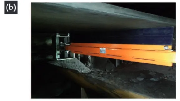
In the blast furnace project, scrap-ers for cleaning the belts were projected. This equipment is indicated by compa-nies that work in the area of the belt con-veyor. So, scrapers have been speciied for elimination of the use of compressed air. The C1 belt scraper project, related
to the point 15 is shown in Figure 1a. It is a polyurethane blade able to clean effectively in extreme environments. The cleaning of the belts is important to prevent material accumulation that can adhere to rollers and other accessories, shortening the life of the assembly and keeping the environment clean. The scraper installed is displayed in Figure 1b.
It is noted in Figure 1b that the compressed air hose has been eliminated and the scraper performs the cleaning function correctly.
(a) (b)
Figure 1 Belt Scraper of the C1 area:
(a) design and (b) installed
Despite the improvements made, it is necessary that they remain so leaks are non-recurring. Therefore, the future implementation of an inspection plan in the compressed air distribution of the blast furnace plant is required. It was found that the identiied problems are arising from the absence of more detailed standard operating procedures and directed activities and responsibilities.
After the implementations, the elec-tricity consumption of the compressors was monitored. Through the supervision system and data acquisition available in the blast furnace plant, the energy con-sumption of compressors was obtained over a deined period.
Table 2 shows the electricity con-sumption of the three compressors from September 2012 to September 2013 as
well as the total cost spent in electricity of the air compressed system. These data refer to the period prior to the elimina-tion of waste points in compressed air system. Table 2 shows that the average electricity consumption of the compres-sors between September 2012 and Sep-tember 2013 was 32,785.42 kWh, which corresponds to an average monthly cost of R$ 52,259.38.
Month Global electricity consumption of compressors (kWh)
Average cost of kilowatt-hour for the power plant
Total cost spend in electricity
Sep/2012 345574.04 R$ 0.17 R$ 58,747.59
Oct/2012 347501.71 R$ 0.17 R$ 59,075.29
Nov/2012 343234.70 R$ 0.20 R$ 68,646.94
Dec/2012 358553.03 R$ 0.18 R$ 64,539.55
Jan/2013 362625.60 R$ 0.17 R$ 61,646.35
Feb/2013 321021.12 R$ 0.15 R$ 48,153.17
Mar/2013 338006.64 R$ 0.18 R$ 60,841.20
Apr/2013 275169.60 R$ 0.15 R$ 41,275.44
May/2013 306282.48 R$ 0.16 R$ 49,005.20
Jun/2013 319464.00 R$ 0.13 R$ 41,530.32
Jul/2013 319570.32 R$ 0.13 R$ 41,544.14
Aug/2013 309504.00 R$ 0.13 R$ 40,235.52
Sep/2013 315223.20 R$ 0.14 R$ 44,131.25
Average 327825.42 - R$ 52,259.38
After performing the improve-ments, the compressors electricity
consumption and the total electric-ity cost spent in the air compressed
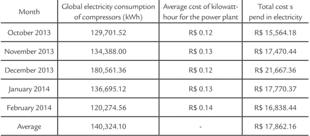
system was monitored and reported in Table 3.
Month Global electricity consumption of compressors (kWh)
Average cost of kilowatt-hour for the power plant
Total cost s pend in electricity
October 2013 129,701.52 R$ 0.12 R$ 15,564.18
November 2013 134,388.00 R$ 0.13 R$ 17,470.44
December 2013 180,561.36 R$ 0.12 R$ 21,667.36
January 2014 136,695.12 R$ 0.13 R$ 17,770.37
February 2014 120,274.56 R$ 0.14 R$ 16,838.44
Average 140,324.10 - R$ 17,862.16
Table 3
Monitoring of electricity consumption of blast furnace compressors after the elimination of air compressed system waste points.
Table 3 shows that from October 2013, the drop in electricity consumption was drastic due to the elimination of the air compressed system’s leakage points.
Note that the average consump-tion of the three compressors fell from 327,825.42 to 140,324.11 kWh per month, which means a reduction of 57.2% in energy consumption. Conse-quently, it was possible to return a com-pressor to stand-by condition, according
to the plant’s initial design, without changing the delivery pressure of the compressed air.
According to the ultrasonic mea-surement prediction, the waste of com-pressed air system required an electrical energy consumption of 33,220 kWh/ month. However, after improvements, the reduction was far greater, showing an average value of 187,501.31 kWh. The difference between the calculated value
and the actual reduction in consumption is due to the fact that the tests only de-tect leaks, and the lowrate calculated in cleaning the C1 and C2 belts were below the real value and thus do not provide the correct compressed air leakage. The drop in electricity consumption is also displayed in Figure 2. In this igure, it is evident that the decrease in electric-ity consumption occurs in the month of October 2013.
Figure 2
Electricity consumption of blast furnace compressors.
Figure 2 displays that the elec-tricity consumption decreased about 185,000 kW between September 2013 and October 2013, which corresponds
to 57.2% of electricity consumption reduction. The decrease in costs because of the elimination of waste points, mainly by the installation of scrapers
in the belts, was around R$ 15,000.00. This study proves the feasibility of eliminating the compressed air system waste points.
4. Conclusions
Compressed air is typically one of the most expensive utilities in an industrial facility. Based on energy assessment of mid-sized industries, compressed air typi-cally comprises from about 5% to 20% of a plant’s annual electric costs (Schmidt and Kissock, 2015). In this paper, it was found that there was no effective
stan-dard operating procedure for inspection and maintenance of the compressed air system of a company, and through an ul-trasonic test, it was found that leaks were responsible for the high electric energy consumption of the compressors. Thus, the elimination of these leaks was made in order to solve the problem, the elimination
427
functioning of the compressed air system and a non-recurring problem, it becomes necessary to create a more detailed stan-dard operating procedure and directed activities and responsibilities. The work
on the energy consumption reduction of the blast furnace of a steelmaking process compressors is of main importance for the understanding of how the bad use of compressed air has a negative impact on
the consumption of electric energy. In this sense, additional studies were proposed to further reduce the energy consump-tion of compressors and, jointly, increase their availability.
Acknowledgments
The authors acknowledge the Bra-zilian Federal University of Ouro Preto
(UFOP) and those who helped in the execution of this project.
References
ALYRIO, R. D. Metodologia cientíica. Rio de Janeiro: PPGEN - UFRRJ.
2008. (In Portuguese).
ATLAS COPCO. Manual do ar comprimido. São Paulo: McGraw-Hill do
Brasil. 1976. (In Portuguese).
CALENTE, A., PIO, A., MENEZES, R. T. Técnicas preditivas ligadas à inspeção. Serra: CST – Arcelor Brasil. 2014. CEMIG 2014. Available
at <http://www.cemig.com.br/ptbr/atendimento/ Paginas/valores_de_ tarifa_e_servicos.aspx>. Accessed on January 2014. In Portuguese.
CRESWELL, J. Qualitative inquiry and research design: choosing among ive traditions. Thousand Oaks. CA: SagePublications, 1998.
DICIONÁRIO MICHAELIS ONLINE. Available at <http://michaelis.uol. com.br/ moderno/portugues/>. Accessed on December 2013.
FERRARI. A. T. Metodologia da pesquisa cientíica. São Paulo:
McGraw--Hill do Brasil, 1982. (In Portuguese).
FIALHO, A. B. Automação pneumática. São Paulo: Editora Érica LTDA,
2007. (In Portuguese).
SCHMIDT, C., KISSOCK, K. Power characteristics of industrial air com-pressors. Available at
https://www.udayton.edu/engineering/centers/in-dustrial_assessment/resources/docs/pdf/Power CharAirComp_IETC2003. pdf. Accessed on June 2015.
FIDELIS, Jocelito. Estudo de eiciência energética em instalações de ar com-primido. São Leopoldo: Universidade Federal do Vale dos Sinos, 2011.
76 p. (In Portuguese - Trabalho de Conclusão de Curso - Graduação em Engenharia Mecânica).
GARCIA, A., SPIM, J. A., SANTOS, C. A. Ensaio dos materiais. Rio de
Janeiro: Livros Técnicos e Cientíicos, 2008. (In Portuguese).
GERHARDT, T. E., SILVEIRA, D. T. Métodos de Pesquisa. Porto Alegre:
Editora UFRGS, 2009. (In Portuguese).
DIAS JÚNIOR, Jair, PEIXOTO, Eliezer. Eiciência energética em sistema de ar comprimido - recuperação do calor de compressão. Bahia: Instituto
Federal de Educação, Ciência e Tecnologia da Bahia, 2010. 31 p. (Trabalho de conclusão de curso - Graduação em Engenharia Industrial - In Portu-guese).
LAKATOS. E. M., MARCONI. M. A. Fundamentos de metodologia cientí-ica. (7 ed.) São Paulo: Atlas, 2010. (In Portuguese).
MACINTYRE. A. J. Instalações hidráulicas. Rio de Janeiro: Livros Técnicos
e Cientíicos, 1996. (In Portuguese).
PARKER AUTOMATION. Dimensionamento de redes de ar comprimido.
São Paulo: 2006. (In Portuguese).
RADUENZ, S. L., DESCHAMPS, E., PÉRES, A. Análise de conservação de energia elétrica nas indústrias do setor metal-mecânico do Alto Vale do Itajaí. Revista E-Tech: Tecnologias para competitividade industrial,
Florianópolis, v. 2, n. 1, p. 1-15, 1º Sem., 2009. (In Portuguese).
RICHARDSON, R. J. Pesquisa social: métodos e técnicas. São Paulo: Editora
Atlas, 1989. (In Portuguese).
ROCHA, C. R., MONTEIRO, M. A. G. Eiciência energética em sistemas de ar comprimido – manual prático. Rio de Janeiro: Eletrobrás; Procel,
ROLLINS, J. P. Manual de ar comprimido e gases. São Paulo: Prentice Hall, 2004.
SANTOS. A. H. M. et al.Conservação de energia - eiciência energética de equipamentos e instalações. Itajubá: FUPAI, 2006. (In Portuguese.)
XENOS, Harilaus G. Gerenciando a manutenção produtiva. Belo Horizonte:
Editora EGD, 2004. (In Portuguese).