Rodrigo E. Catai
[email protected] Universidade Tecnológica Federal do Paraná Curitiba, PR, BrazilEduardo C. Bianchi
Senior Member, ABCM [email protected]
Felipe M. Zilio
Ivan de D. Valarelli
Manoel C. de S. Alves
Leonardo R. Silva
Paulo R. de Aguiar
[email protected] Faculdade de Engenharia de Bauru Universidade Estadual Paulista - UNESPBauru, SP, Brazil
Global Analysis of Aerodynamics
Deflectors Efficiency in the Grinding
Process
The conventional grinding methods in some cases are not very efficient because the arising of thermal damages in the pieces is very common. Optimization methods of cutting fluid application in the grinding zone are essential to prevent thermal problems from interaction of the wheel grains with the workpiece surface. The optimization can happen through the correct selection of the cut parameters and development of devices that eliminate air layer effects generated around the grinding wheel. This article will collaborate with the development of an experimentation methodology which allows evaluating, comparatively, the performance of the deflectors in the cutting region to minimize the air layer effect of the high speed of the grinding wheel. The air layers make the cutting fluid jet to dissipate in the machine. An optimized nozzle was used in order to compare the results with the conventional method (without baffles or deflectors) of cutting fluid application. The results showed the high eficciency of the deflectors or baffles in the finish results.
Keywords: Optimized application, Grinding process, Cutting fluid, Baffles, Deflectors.
Introduction
Through the years, the grinding process has been considered as one of the most important in manufacturing. It is a high precision and important process, once the loss of a workpiece at this stage of the process is unacceptable. This occurs because the aggregated value to the material is quite high due to the several machining processes that commonly precede the grinding process (Soares, 2001).
In the grinding process, the workpiece is forced against the grinding wheel, generating chips that are removed from the workpiece surface (Gupta et al., 2001). During the chip formation, part of the generated energy is converted into heat, causing high temperatures at the cutting region, which may cause thermal damages to the workpieces (Kovacevic & Mohan, 1995).1
In order to control the high temperatures at the cutting region, which may damage either the workpiece or the tool, and with the purpose of minimizing as much as possible the costs regarding the fluid waste due to ineffective application, the grinding process optimization has become more and more necessary. This may occur by the correct choice of the fluid-tool interaction, through the use of ideal cutting parameters and by the adoption of optimized systems of cutting fluids application, once through conventional methods, the energy stored in the fluid during its application, in most cases, is not sufficient to overcome the grinding wheel’s centrifugal force or to penetrate the air barrier around the moving grinding wheel.
This work intends to analyze whether the use of a deflectors system would improve the grinding process performance. In that purpose, the grinding process monitoring, as well as a further output variables analysis, such as the cutting tangential force, the grinding wheel radial wear, the workpiece surface roughness and the roundness errors found in the workpieces will be done.
Paper accepted October, 2005. Technical Editor: Atila P. Silva Freire.
Process Optimization
The process optimization increases the fluid cooling and lubricating capacity, furthers the chip removal more easily, generates less dispersions at the cutting region; however, the correct nozzles positioning is required (Ebbrell et al., 1999).
Some factors straightly affect the cooling efficiency, including the type and velocity of the employed fluid, the nozzle positioning, the nozzle opening angle, the nozzle project, the use of a device in order to break the air barrier around the grinding wheel and the size of the grinding wheel abrasive grains (Campbell, 1995).
The employment of conventional and optimized nozzles: The employment of conventional nozzles for regulating and directing the flow of fluid is no longer adequate due to the growth of the employment of water-base fluids, which generate great dispersion and disappear at the cutting region due to the air barrier around the grinding wheel through its high rotation. This air barrier may be overcome when the jet outlet velocity is equal to the grinding wheel peripheral velocity; however, the jet efficiency is decreased due to the incorrect conventional nozzles design and to the pump pressure raise, aiming to increase the fluid outlet velocity, leading to an increase in the jet dispersion.
This way, special nozzles have been developed in order to allow the effective arrival of the fluid jet at the cutting region.
According to Webster (1995), the ideal nozzle would be round-shaped with concave internal walls, what would minimize the occurrence of pressure drop and turbulence during the fluid passage and outlet, also guaranteeing higher jet coherence.
Special nozzles with a bolt around the grinding wheel: these nozzles are quite efficient and adjustable to a wide range of grinding wheels sizes and count on a type of bolt, which should be connected to the nozzle and adjustable to different grinding wheels diameters (Silliman, 1992).
Coolant bracket and deflectors: the deflectors and the coolant bracket have the function of eliminating the air curtain formed around the grinding wheel due to its rotation, which makes the coolant intake at the cutting region difficult. In operations where high cutting velocities are used, this air layer is even more relevant, whereas the velocity and pressure of such air layer exponentially decrease with the reduction of the radial distance in relation to the grinding wheel center. As this air layer is reduced or eliminated, especially when high cutting velocities are required, the cutting forces and the roughness values, from 40% to 60% and from 10% to 20% respectively, may also be reduced.
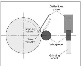
In order to eliminate this air film, Bellows (1983) proposes the placement of deflective plates covering the grinding wheel contour, placed above the fluid outlet nozzle, as illustrated on Fig. 1.
Figure 1. Layout of a deflective plate around the grinding wheel (Bellows, 1983).
According to Catai et al. (2002), one of the ways of eliminating such air layer generated by the grinding wheel is through the employment of deflectors systems, according to Fig. 2.
Rebolo
Sistema de
defletores
Bico de saída
de fluido
Peça
Roundness Errors
According to Jedrzejewski & Modrzycki (1997), the roundness error, as illustrated in Fig. 3, may be understood as any divergence between the manufactured workpiece and the workpiece theoretically required with specified tolerance. The amount of errors in a workpiece gives its accuracy measure.
One factor of great relevance, which contributes to the formation of roundness errors and to the final status of the ground workpiece is the high friction generated during the grinding process (Minke, 1999). Thus, the employment of cutting fluids with higher capacity for friction reduction and therefore the reduction of the consequent heat generation is essential.
Figure 3. Example of a workpiece with roundness error (Taylor-Hobson, 2001).
Methodology
Six tests were performed in this work, whereas three tests had no employment of deflectors system in the grinding machine (tests 1, 2 and 3) and the other three had the employment of such system (tests 4, 5 and 6). The material of the workpieces was the VC 131 steel tempered and quenched, with hardness of 60 HRc.
The Fig. 4 illustrates the employed grinding process. One can easily notice the employed optimized nozzle of 3 mm diameter, the conventional grinding wheel and the workpiece fixed.
Figure 4. Grinding process with optimized nozzle, conventional grinding
Grinding wheel
Workpiece Deflectors
system
Nozzle to application of
* Grinding wheel peripheral velocity (Vs) of 33m/s; * Fluid outlet velocity (Vj) of 33m/s;
* Pressure of cutting fluid of 5 kgf/cm2;
* Grinding wheel: aluminum oxide conventional grinding wheel 19A100SVHB;
* Cutting fluid: integral oil; * Spark-out time of 5 seconds;
Before the beginning of each test, the conventional grinding wheel was dressed, allowing the attainment of the adequate aggressiveness, keeping the same tool initial condition for all tests. The dressing was performed through a fleeze-type dresser, removing 0.2mm from the grinding wheel radius. A 5mm wear on the workpieces diameter was made for the analyses, at 50 cycles of 0.1mm.
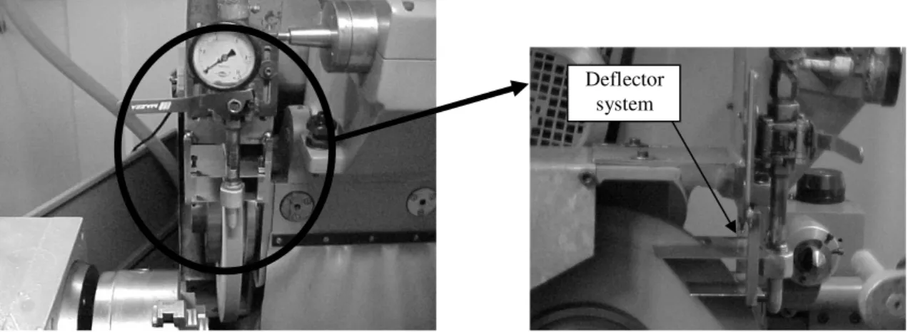
The deflectors system employed during the tests is similar to the system proposed by Bellows (1983) and Catai et al. (2002). In Fig. 5 is presented the aerodynamic deflector used in this work.
Another important factor that should be emphasized regarding the tooling conditions, is the used nozzle, which is an optimized system with 3 mm diameter. Its performance seems to be better than the conventional system, once through high pressure, the aerodynamic barrier generated by the grinding wheel may be overcome, and thus the cutting fluid may effectively penetrate into the region of contact between grinding wheel and workpiece (Monici, 2003).
Results
Next, the results obtained for the following analyzed variables will be shown: cutting tangential force, workpiece surface roughness, roundness errors and grinding wheel radial wear.
It is worthy emphasizing that the used cutting fluid was integral oil and the grinding wheel, an aluminum oxide conventional one.
Results of Cutting Force
The cutting tangential force was indirectly measured by measuring the electric power of the 3-phase induction motor that drives the wheel. This was made through the monitoring of the voltage and current values from piezoelectric and hall sensors respectively, and then multiplying these values in order to obtain the electric power consumed by the induction motor. The power signal was sent to a data acquisition board and handled by the LabVIEW® software from National Instruments. A calibration curve was obtained in order to get the cutting force in the process.
The analysis of the cutting force results was performed through graphics containing several curves, where each curve represents results of one test, as shown in Fig. 6 and 7.
It is important emphasizing that for each point in the graphic of Fig. 8, an arithmetic average of the maximum points was obtained from three-test repeatability.
Observing Fig. 8, it can be noted that with the employment of deflectors system in the grinding processes, the cutting force was reduced by 5.5%; then using the deflectors, the forces required to the grinding wheel cutting the workpieces are lower. This happened because the cutting fluid got into the grinding zone easier, lubricating and cooling more efficiently the workpiece and the grinding wheel.
Therefore, it is clear that eliminating the air around the grinding wheel, the grinding wheel can more easily machine the surface of the workpiece.
Figure 5. Deflector system used in the tests.
Figure 6. Cutting forces for the tests without deflectors.
Figure 7. Cutting forces for the tests with deflectors.
Figure 8. Cutting forces for the tests with and without deflectors.
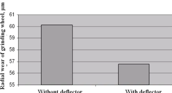
Results of Radial Wear
The radial wear values were obtained through the marking of the grinding wheel wear in a rod-shaped piece of SAE 1020 steel after each test. This rod had many markings; each marking was rightly indicated according to the test number. Once only part of the grinding wheel was used in the performed tests, the other part was
With the employment of the deflectors system, the wear was 5.5% smaller, in other words, the tool’s useful life is longer with the employment of the deflectors system.
Therefore, it is clear that there is a higher wear on the abrasive tool in machining conditions with no deflectors, proving the efficiency of the deflectors system.
Results of Roughness
The surface roughness values were obtained through a roughness checker from Taylor Hobson, model Sutronic 3+, as shown in Fig. 10.
The surface roughness results are presented in the graphic of Figure 11, where each point represents the average of three tests, whereas in each test, seven measurements on the workpiece surface were performed.
It can be seen in Fig. 11 an improvement of 2.8% in the surface roughness for grinding without the proposed deflectors system, whereas one could say that the surface roughness for both is quite the same, once the difference found was of 0.01 m.
Possibly, the roughness for both cases was quite the same because the peripheral velocity of the grinding wheel was very low. Perhaps with a higher velocity, a significant difference of the surface roughness between the process with and without deflectors can be noted.
Figure 9. Grinding wheel radial wear for grinding process with and without deflectors system.
Figure 11. Comparison of surface roughness between systems with and without deflectors.
Results of the Roundness
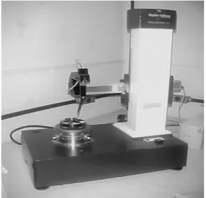
For the performance of the roundness measurements, a TAYROND 31C equipment was employed, as shown in Fig. 12.
Figure 12. Photograph of the roundness measurer.
The roundness values were obtained through the average of three tests, according to Fig. 13, whereas for each test, three measurements were performed.
It can be noted analyzing the Fig. 13 that the use of deflector was efficient, because the tests presented the lowest roundness.
The roundness errors were around 1µm higher for the tests with no deflector, which show the efficiency of the defector system.
The roundness errors were lower when the deflectors were used because this system has eliminated the air around the grinding wheel, allowing the cutting fluid to penetrate more easily into the grinding zone and, in turn, lubricating and cooling more efficiently the workpiece and the grinding wheel.
Figure 13. Comparison of roundness values obtained for grinding with and without deflectors.
Conclusion
Through this work, the behavior of the external cylindrical plunge grinding could be observed, with and without the employment of the deflectors system.
According to the graphics obtained, the employment of deflectors allowed the reduction of the cutting force values by 5.5% and the grinding wheel radial wear by 5.5%. The surface roughness values showed difference of 0.01 m, in other words, the surface roughness had an improvement of 2.8% without the employment of deflectors whose difference is not significant.
The roundness errors values were smaller (about 19.2%), when the deflectors system was employed in order to eliminate the air layer generated by the grinding wheel.
Therefore, the use of deflectors system is the best choice for industries, which look for a better quality of surface finishing with less tool wear. This system has been proved, in this work, to minimize the air layer effect due to the high peripheral velocity of the grinding wheel, which is responsible for dissipating the fluid jet in the grinding process.
References
Bellows, G. 1983, “Low stress grinding – For quality production”. Machining Process Series, Metcut Research Associates Inc., Second Edition, Cincinnati, Ohio, p.49-95.
Brinksmeier, E.; Heinzel, C.; Wittmann, M.; Schmid, U.; Dreyer, M.; Rath, H. J. 2001, “How the application of cutting fluid can be better in the grinding process”. Máquinas e Metais, Brazil, October, p. 34-41.
Campbell, J. D. 1995, “Optimized Coolant Application”. Technical Paper, MR95-211, Society of Manufacturing Engineers.
Catai, R. E., Bianchi, E. C., Aguiar, P. R. 2002, “Optimization of grinding process through the analysis of the quantity of cutting fluid used”. In: Brazilian Congress of Engineering and Science of Materials – CBECIMAT, Natal, RN, Brazil.
Ebbrell, S.; Woolley, N.H.; Tridimas, Y.D.; Allanson, D.R.; Rowe, W.B. 1999, “The effects of cutting fluid application methods on the grinding process”. International Journal of Machine Tools & Manufacture, United Kingdom, June.
Gupta, R.; Shishodia, K. S.; Sekhon, G. S. 2001, “Optimization of grinding process parameters using enumeration method”. Journal of Materials Processing Technology, p. 63-64.
Jedrzejewski, J.; Modrzycki, W. 1997, “Intelligent supervision of thermal deformations in high precision machine tools”. Proceedings of 32nd International MATADOR Conference, Manchester, UK, pp. 457–462.
Kovacevic, R; Mohan, R. 1995, “Effect of high speed grinding fluid on surface grinding performance”. SME Technical paper MR95-213, p. 919-931.
Minke, E. 1999, “Contribution to the role of coolants on grinding process and work results”. 3rd International Machining & Grinding Conference, October 4-7, Westin Hotel, Cincinnati, Ohio.
Ramesh, K.; Yeo, S. H.; Zhong, Z. W.; Sim, K. C. 2001, “Coolant shoe development for high efficiency grinding”. Journal of Materials Processing Technology, p. 240-245.
Silliman, J. D. (Ed.). 1992, “Cutting and grinding fluids: selection and application”. Dearborn, Michigan: SME, Second Edition, p. 119-135, ISBN: 0-87263-423-X.
Soares, D. D., Oliveira, J. F. G. 2001, “Diagnostics of grinding process through the analysis of signals”. In: XVI Brazilian Congress of Mechanical Engineering - COBEM, ABCM, Brazil, 266p.
Taylor-Hobson. 2001 “TAYROND 31C machine handbook”.