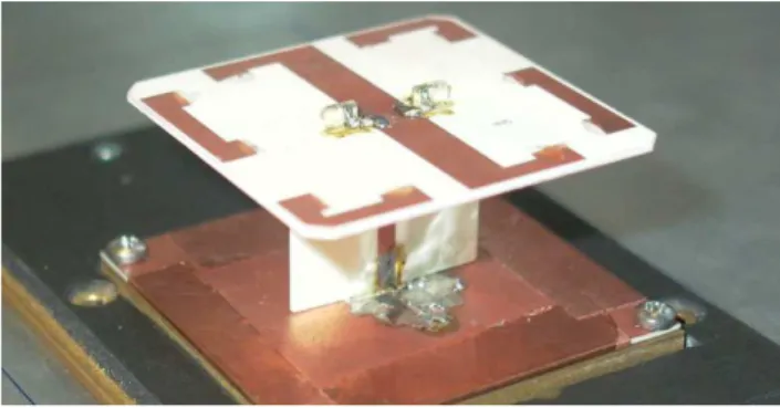
Antenna with optimized pattern for simultaneous reception of terrestrial signals and signals of geostationary satellites
Texto
Imagem

Documentos relacionados
Greater gains in experimental precision (16%) with increases in plot size, occurred up to eight basic units (5.04 m 2 ) using seven replications.. Increasing the number of
Bem como as relações entre Brasil e Argentina, permeadas por profundos dilemas e por soluções (e em certos momentos, crises!) moldadas pelo mundo da Guerra Fria, uma
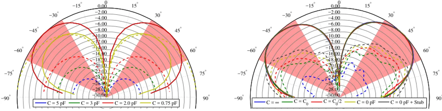
These can be explained due to the fact that the antenna gain is optimized by the resonant frequency, but in this paper the rectangular patch and triangular slot
The structure of the remelting zone of the steel C90 steel be- fore conventional tempering consitute cells, dendritic cells, sur- rounded with the cementite, inside of
Rather than the term frequency response function, this is called the transfer function of the system, and in terms of the Laplace transforms X s ( ) and Y s ( ) of the
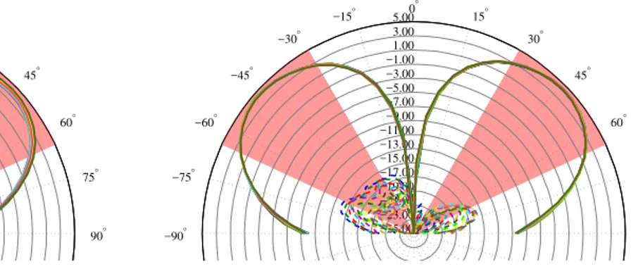
Theoretical and experimental results of return loss, axial ratio, input impedance and radiation pattern for the antenna located on the aluminum and CFC plates
In [5] is shown an exponential TEM horn antenna with binomial radiation planes presenting directional radiation patterns, but to the detriment of gain (less than
The aim of the proposed algorithm is to obtain the optimum values for inter-element spacing and excitation amplitude for a linear antenna array in a given radiation pattern
