Abstract— In this paper a truncated corner rectangular microstrip antenna (TCRMA) is analyzed in the presence of carbon fiber composite (CFC) material. Simplified carbon fiber composite models are proposed and the analyses are performed by the electromagnetic simulator Computer Simulation Technologies (CST). Theoretical and experimental results of return loss, axial ratio, input impedance and radiation pattern for the antenna located on the aluminum and CFC plates are presented and compared. The results show that the proposed models can be used as a good approximation of the CFC sample and that the CFC material is a feasible alternative instead of aluminum for antenna applications on complex structures such as ships or airplanes.
Index Terms—Carbon fiber composite (CFC), microstrip antenna.
I. INTRODUCTION
The search for new improved materials that could replace the aluminum or other conductors is a
common task for many applications in the aerospace industry. Weight reduction, more tolerance to
fatigue and easiness of construction for complex structures are some advantages of using such
materials. These characteristics can lead to operational costs reduction and performance increase. The
carbon fiber composite (CFC) is a successful and well-know example of such materials in many
applications. Several studies have been made in recent years to analyze the CFC electrical properties
[1]-[5]. However, some technical aspects still aren’t fully explored by the scientific community, such
as the antenna behavior in the presence of these materials. There are several antenna topologies that
require a conductive ground plane in order to properly operate, and the knowledge of their behavior in
such environment is important to establish an optimal operational condition.
This paper presents theoretical analyses to evaluate the figures of merit of a circular polarized
truncated corner rectangular microstrip antenna (TCRMA), which is designed to operate in the
satellite navigation frequency range, in the presence of the CFC material. The approach is to consider
a fictitious custom-off-the-shelf (COTS) antenna and analyze it on a CFC ground plane as this is
considered a practical situation. The trend in the aerospace industry is the replacement of certain
structural parts by composite materials [6], and the analysis of these materials at high frequencies
Analysis of Microstrip Antennas on Carbon
Fiber Composite Material
Rodrigo R. de Assis* and Ildefonso Bianchi**
Department of Electronic and Computer Engineering, Instituto Tecnológico de Aeronáutica, São José dos Campos – SP, Brazil,
using numerical techniques requires great computational effort as the dimensions are electrically large
[7]. Thus, the search for faster and more accurate solutions is still a challenge, mainly considering the
possibility of analyses on larger structures such as ships or airplanes. Theoretical results are compared
with experimental ones for CFC and aluminum samples.
II. DESCRIPTION OF CFCMATERIAL
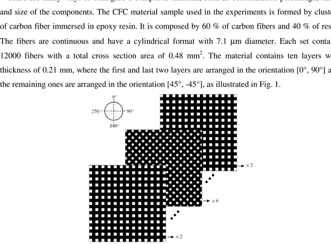
There are many ways to configure a composite material, such as concentration percentage, shape
and size of the components. The CFC material sample used in the experiments is formed by clusters
of carbon fiber immersed in epoxy resin. It is composed by 60 % of carbon fibers and 40 % of resin.
The fibers are continuous and have a cylindrical format with 7.1 µm diameter. Each set contains
12000 fibers with a total cross section area of 0.48 mm2. The material contains ten layers with
thickness of 0.21 mm, where the first and last two layers are arranged in the orientation [0°, 90°] and
the remaining ones are arranged in the orientation [45°, -45°], as illustrated in Fig. 1.
Fig. 1. CFC sample with layers details and fibers orientation.
Due to the complexity of modeling the real geometry, witch requires a great computational effort,
the theoretical analyses are made using two simplified models of the CFC plate. Moreover,
comparisons with experimental results are made to validate the proposed simplification. In the first
model (CFC[a]) the electrical conductivity and effective permittivity of the material are estimated
through the law of mixtures [8], [9]
res carb
eff vP v P
P = +(1− ) , (1)
where P indicates electrical permittivity (ε) or conductivity (σ), v is the percentage of carbon in the
CFC, the indexes carb and res denote parameters of carbon and resin, and the index eff denotes the
effective parameters of the CFC. Considering the relative permittivities εres = 4.0 and εcarb = 12.0, the
electric conductivities σres = 0 and σcarb = 1.0 x 10⁵ S/m, and the percentage of carbon v = 0.6, it is
material with the above shown effective parameters, relative magnetic permeability µr = 1 and null
loss tangent. The second model (CFC[b]) consists of carbon strips embedded in epoxy resin, as
illustrated in Fig. 2, which represents one layer of the material used in the experiments. The carbon
strips are spaced 2.2 mm and have a rectangular cross section of 2.2 x 0.1 mm. The carbon material is
modeled with εcarb = 12, µr = 1 and σcarb = 1 x 10⁵ S/m, and the epoxy resin layer has a thickness of
0.202 mm, εres = 4 and null loss tangent.
Fig. 2. Detail of the simplified CFC[b] material model.
III. MICROSTRIP ANTENNA BEHAVIOR IN THE PRESENCE OF CFCMATERIAL
The placement of a COTS antenna on a large structure is a common situation in the aerospace
industry. In this case the antenna is usually designed on a flat ground plane and its behavior is
expected to be similar when installed on large complex structures. In new applications these structures
are being replaced by composite materials due to their mechanical benefits and the behavior of an
antenna installed on these materials can be a challenging task in many aspects, such as mechanical
installation, lightning protection or static discharge. Besides, the behavior of antennas’ figures of
merit is also not fully explored in the scientific community. In order to evaluate these features it is
chosen a circular polarized microstrip antenna with truncated corners, as depicted in Fig. 3. This
antenna was chosen due to its narrow bandwidth considering both the circular polarization and the
input impedance, as any small change in the antenna surroundings can influence these tune features.
The antenna is designed on a 30 x 30 cm aluminum plate, as shown in Fig. 3, to operate at the
center frequency of 1575 MHz and with right-hand circular polarization. The substrate is Arlon
CuCLAD 250GX with a thickness of 3.048 mm, εr = 2.55 and loss tangent of 0.0018. The dimensions
of the antenna are: W = 85.0 mm, L1 = 57.9 mm, L2 = 57.3 mm, C = 6.2 mm, p = 16.5 mm. The
antenna has its own conductive ground plane limited by the substrate dimensions (W) and the material
Fig. 3. TCRMA on the 30 x 30 cm plate.
The theoretical analysis is performed by the CST simulator, where the frequency domain was used
for the CFC[a] model and the time domain was used for the CFC[b] model. The input impedance and
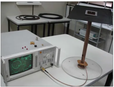
return loss measurements were made using the vector network analyzer HP 8714ET in the Antenna
and Propagation Laboratory at Instituto Tecnológico de Aeronáutica (ITA) and the axial ratio and
radiation pattern measurements were performed in the anechoic chamber of Instituto de Fomento
Industrial (IFI), both part of Departamento de Ciência e Tecnologia Aeroespacial (DCTA), as shown
in Figs. 4 and 5.
The theoretical and experimental results of return loss, axial ratio, input impedance and radiation
pattern for the antenna located on the aluminum and CFC plates are shown in Figs. 6 and 7.
The results of axial ratio and return loss for the TCRMA antenna without the 30 x 30 cm plate are
also shown in Fig. 6 (a) and Fig. 7 (b). From these results it can be concluded that the antenna features
are degraded in the condition without the plate.
Fig. 5. Measurement set-up for TCRMA on CFC plate (axial ratio and radiation pattern).
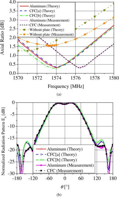
1570 1572 1574 1576 1578 1580
0.0 0.5 1.0 1.5 2.0 2.5 3.0 3.5 4.0 A x ia l R at io [ d B ] Frequency [MHz] Aluminum (Theory) CFC[a] (Theory) CFC[b] (Theory) Aluminum (Measurement) CFC (Measurement) Without plate (Theory) Without plate (Measurement)
(a)
-180 -120 -60 0 60 120 180
-30 -25 -20 -15 -10 -5 0 N o rm al iz ed R ad ia ti o n P at te rn E θ [ d B ]
θ [°]
Aluminum (Theory) CFC[a] (Theory) CFC[b] (Theory) Aluminum (Measurement) CFC (Measurement) (b)
As presented in Fig. 6 (a), the theoretical axial ratio results for the CFC plate are similar to the
theoretical values obtained for the aluminum plate. The small difference between these values doesn’t
change the condition of circularly polarized antenna. Similarly the experimental results do not present
significant variation comparing the aluminum and the CFC plates. The small displacement between
the points of best axial ratio, when comparing theoretical values with experimental ones, is within the
substrate material tolerances provided by the manufacturer and it corresponds to 0.09% of the design
frequency. It was also noted that this difference does not compromise the correct operation of the
antenna. The radiation pattern in the yz plane at the frequency of 1576.5 MHz is shown in Fig. 6 (b).
The maximum difference between theoretical and experimental results was approximately 0.2 dB.
These results indicate that the radiation pattern is not significantly changed when replacing the
aluminum plate by CFC plate.
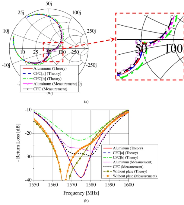
10 25 50 100 250
-10j 10j
-25j 25j
-50j 50j
-100j 100j
-250j 250j
Aluminum (Theory) CFC[a] (Theory) CFC[b] (Theory)
Aluminum (Measurement) CFC (Measurement)
(a)
1550 1560 1570 1580 1590 1600
-40 -30 -20 -10
-
R
et
u
rn
L
o
ss
[
d
B
]
Frequency [MHz]
Aluminum (Theory) CFC[a] (Theory) CFC[b] (Theory) Aluminum (Measurement) CFC (Measurement) Without plate (Theory) Without plate (Measurement)
(b)
The input impedance results considering the aluminum and CFC plates were also similar, as shown
in Fig. 7 (a). The maximum percentage deviation at the frequency of 1575 MHz was 0.1% (CFC[a]),
11.7% (CFC[b]) and 1.8% (measured CFC sample), considering the reference being the antenna on
the aluminum plate. In Fig. 7 (b) it is noted that the CFC[a] model exhibited a return loss similar to
the theoretical model of the aluminum plate and both had a deviation of about 11 dB at 1575 MHz
compared to measured results. The CFC[b] model presented a deviation of about 4 dB from measured
values at 1575 MHz. However, as these results were below 22 dB, it can be concluded that replacing
the aluminum plate by CFC plate does not significantly degrade the return loss of the antenna.
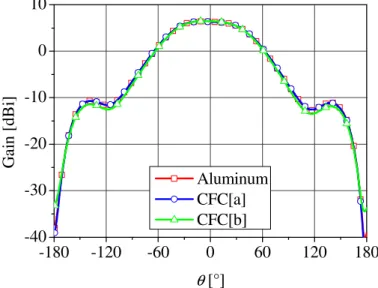
The theoretical antenna gain results for aluminum and CFC plates in the yz plane at 1576.5 MHz are
shown in Fig. 8. The gain for the three material models is about 6 dBi and its variation is less than
2%. Thus, it is concluded that the use of CFC plate does not degrade significantly the antenna
efficiency in comparison to the aluminum plate. This result emphasizes the advantage of keeping the
metallic antenna ground plane underneath its substrate.
-180 -120 -60 0 60 120 180
-40 -30 -20 -10 0 10
G
ai
n
[
d
B
i]
θ [°] Aluminum CFC[a] CFC[b]
Fig. 8. Theoretical right hand circular polarization antenna gain results in the yz plane at 1576.5 MHz.
IV. CONCLUSIONS
The analysis of composite materials at high frequencies using numerical techniques requires large
computational effort, making the search for faster and more accurate solutions a challenge, mainly
considering the possibility of analyses on larger structures such as ships or airplanes. This paper
presented theoretical and experimental analysis of the TCRMA’s figures of merit in the presence of a
carbon fiber composite sample, where simplified material models were proposed in order to reduce
the computational effort. The agreement between theoretical and experimental results shows that the
proposed CFC material models can be used as a good approximation of the CFC sample, enabling
analyses of antennas in the presence of more complex and electrically large structures such as
aluminum under the studied conditions. Thus, it can be concluded that the CFC material is a feasible
alternative instead of aluminum for antenna applications on complex structures such as ships or
airplanes.
REFERENCES
[1] C.P. Neo and V.K. Varadan, Design and development of electromagnetic absorbers with carbon fiber composites and matching dielectric layers, IOP Electronic Journals, Smart Materials and Structures, October 2001.
[2] S. Bhattacharya, V.K. Sachdev and R.P. Tandon, Electrical properties of graphite filled polymer composites, 2nd National Conference Mathematical Techniques: Emerging Paradigms for Electronics and IT Industries, September 2008.
[3] A. Cîrciumaru, G. Andrei, I.G. Bîrsan and D. Dima, Electric and electromagnetic properties of fiber fabric based filled epoxy composites, The Annals of "Dunarea De Jos" University of Galati, Fascicle IX. Metallurgy and Materials Science, nº 2, pp. 26-28, ISSN 1453, 2007.
[4] I.M. Rosa, F. Sarasini, M.S. Sarto and A. Tamburrano, EMC impact of advanced carbon fiber/carbon nanotube reinforced composites for next-generation aerospace applications, IEEE Transactions on Electromagnetic Compatibility, vol. 50, nº.3, pp. 556-562, August 2008.
[5] A. Mehdipour, A.-R. Sebak, C. W. Trueman, I. D. Rosca, and S. V. Hoa, “Performance of microstrip patch Antenna on a reinforced carbon fiber composite ground plane,” Microwaves and Optical Technology Lett., vol. 53,no. 6, pp. 1328-1331, 2011.
[6] SAE International, CNC fiber placement used to create an all-composite fuselage, Aerospace Engineering & Manufacturing Online, available in: www.sae.org/aeromag/techinnovations/1298t08.htm, access in: April 13, 2010. [7] R.R. de Assis, I. Bianchi and R. Schildberg, Análise de antenas sobre compósito de fibra de carbono para aplicações em
aeronaves, 14th Simpósio Brasileiro de Microondas e Optoeletrônica and 9th Congresso Brasileiro de Eletromagnetismo, Vila Velha - ES, August 2010.
[8] S.E. Lee, K.S. Oh and C.G. Kim, Electromagnetic characteristics of frequency selective fabric composites, IEEE Electronic Letters, vol. 42, issue 8, pp. 439-441, April 2006.
![Fig. 2. Detail of the simplified CFC[b] material model.](https://thumb-eu.123doks.com/thumbv2/123dok_br/18887673.424212/3.892.251.664.286.556/fig-simplified-cfc-b-material-model.webp)