Abstract— Graded components are a resource-conserving alternative to today’s composite materials. Functional gradation means a steady progress of the property values through the three spatial dimensions of the component. At the present time there is no methodology to specify the graded properties in the component description. Its starting point takes place in the conventional CAD-Models, based on Voxel models. The component geometry is reproduced with the aid of voxels. Each single Voxel is linked with the component properties. The effort of the description is reduced by the use of interpolation techniques. As a result, we have an enhanced component model which contains all the necessary information for the description of a functional graded component. This model constitutes the starting point of the process chain planning for the component production.
Index Terms—functional gradation, graded properties, component description, voxelmodel
I. INTRODUCTION
The functions of mechanical components are frequently the result of innovative material combinations and a complex geometry. This applies especially for high performance components in the automobile and aviation industry. Graded components are a resource-conserving alternative to today’s
composite materials. “Functional gradation is the targeted
and reproducable adaptation of a material´s microstructure with the intention to establish the macroscopic properties of the component. The objective is the steady progress of the microstructure´s variation through at least one spatial di-mension.” [1] In different places of the component are lo-cated apparently contradictory properties, which specifically support the posterior function of the component.
Nevertheless only one material is used. Among other things it is possible to define the hardness and the damping behavior through the cross-section of the component. This definition takes place within the manufacturing process. The investigation of graded structures and their manufacturing process is the goal of the collaborative research center
Manuscript received March 2, 2009. This work was supported in part by the German Research Foundation (GRF) within the collaborative research center Transregio 30 (CRC/TR TRR30).
Dipl.-Wirt.-Ing. D. Dettmer is research assistant with the Heinz Nixdorf Institute, University of Paderborn, 33102 Paderborn, Germany (phone: ++49 5251 606262; fax: ++49 5251 606268; e-mail: Do [email protected]).
Dipl.-Wirt.-Ing. J. Brökelmann is research assistant with the Heinz Nixdorf Institute, University of Paderborn, 33102 Paderborn, Germany (e-mail: [email protected]).
Prof. Dr.-Ing. J. Gausemeier is professor with the Heinz Nixdorf Institute, University of Paderborn, Paderborn, 33102, Germany (e-mail: Juer [email protected]).
Transregio 30 (CRC/TR TRR30).
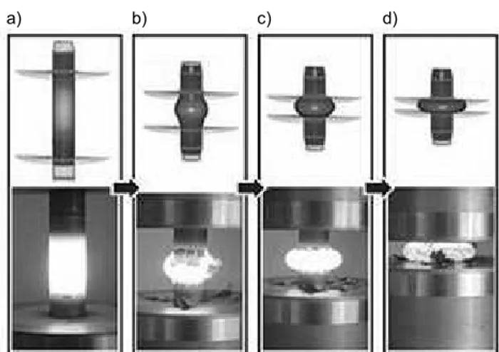
Within the scope of the CRC, a flanged steel shaft is used as demostrator of a component with graded properties. The flanged steel shaft is produced in a three-steps-process (figure 1). With the aid of an induction coil, a steel cylinder is locally heated a) and after that, through a two-steps defor-mation, the cylinder is transformed into a flanged steel shaft. The reshape process consists of the steps: b) + c), which are tool-independent, and the step c), which is tool-dependent.
After the deformation, the flanged shaft is cooled down. There are two types of cooling: contact-cooling, which takes place inside of the forming tool; outside of the tool, with the aid of compressed air cooling. The gradation takes place within the manufacturing process by the use of a new thermo-mechanically coupling process. Among other things it is possible to define the hardness, the tenacity and the damping behaviour.
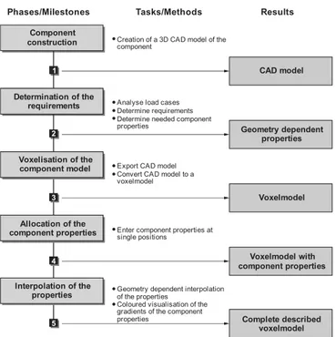
For the planning of manufacturing processes of compo-nents with graded properties was developed a five-steps-systematic:
Component description: For this step exists the necessity of projecting the graded properties of the component into a CAD model. From this CAD model is created a voxelmodel. Each single volume element (voxel) can be linked with in-formation of the component properties.
Determination of manufacturing functions: The pro-duction engineer determines the manufacturing functions based on the enhanced component model. In the future it is planned to assist the production engineer with heuristics and cognition. For each manufacturing function are determined manufacturing technologies. The selection is supported by an
Description of Components with
Graded Properties
D. Dettmer, J. Brökelmann and J. Gausemeier
a) b) c) d)
Fig. 1: Transforming process of the steel shaft (Prof. Steinhoff, University of Kassel)
Proceedings of the World Congress on Engineering 2009 Vol I WCE 2009, July 1 - 3, 2009, London, U.K.
expert system. Afterwards, the functions and technologies are mapped into a morphological matrix.
Synthesis of the process chain: The manufacturing technologies are evaluated against each other in a consistency matrix. This analysis provides highly consistent combina-tions of manufacturing technologies. The consistent tech-nologies` combinations are used to create process chains. A process chain is a chain of manufacturing technologies in which for each manufacturing function a manufacturing technology is assigned.
Process chain optimization: The relationships between the manufacturing technologies and the component proper-ties are described by empirical models. The models of each technology are combined and used in the optimization process. By a multi-objective optimization the values of the parameters of each manufacturing technology are optimized with regard to the desired component properties. Finally a hierarchic optimization is used to optimize the process chain. The optimization is applied in all the consistent process chains.
Specification of the process chain: The optimization process delivers a process chain which can manufacture the graded properties in an optimal way. The process chain is specified with the optimized parameters´ values of the se-lected manufacturing technologies. Thereby, a specification technique which enables the description of the process and resources is used. With this, a funded conception of a manufacturing system for the production of a component with graded properties is available. This conception consti-tutes the starting point of the manufacturing system´s con-cretization in the domains: production resource planning, shop floor planning and production logistics [2].
II. CONCEPT OF THE WORK
In this work, we present a procedure model for the de-scription of components with graded properties. Through the focused construction of components for the intended appli-cation there are property characteristics. These must expand into the component description and require a new method-ology for the description.
To present continuous properties modifications within the component geometry it is insufficient to describe only the surface of the component. Today´s methods for the compo-nent description, like for example the Boundary Representa-tion Method or the Constructive Solid Geometry Method, describe in this way. Component models that are made with the aid of the Boundary Representation Method, describe the component only through delineating edges and areas. An enhancement of this method is the Constructive Solid Ge-ometry Method. With this method, the component is de-scribed through the combination of different bodies. The bodies are linked to each other through Boolean operations and represent a 3D model of the component [3],[4].
None of the mentioned methods enables us neither to se-lect any desired point inside the volume nor to describe this point through a linkage with the properties` information. Furthermore no three-dimensional property characteristics are mapped into the component models, but this is necessary for the description of components with graded properties.
Because of this, a methodology for the description of
components with graded properties was developed in the sub-project D5 of the CRC TR30. This enables the integra-tion of important properties in the component model which are relevant for the component description.
III. PROCEDURE MODEL
It was developed a procedure model for the description of functional graded components. In the figure 2 are presented the phases of the component description.
Fig. 2: Procedure model for the description of functional graded components
In the following paragraphs, each phase is explained with the aid of the flanged steel shaft demonstrator.
A. Component construction
Initially, the component is made in a 3D CAD system. After that, the CAD model is exported to the next processing stage. In this phase, there is no difference between the de-scription of traditional components and graded components [5].
B. Determination of the Requirements
The required graded properties are determined by the ex-pected application of the component. For each application case are designated load cases. From these cases, the com-ponent requirements are derivated. The constructor has to translate these requirements into concrete component prop-erties. The properties of the functional graded components are dependent of the geometry. This implies that also the position in the component is important and must be consid-ered. Because the characteristics have a three-dimensional continious distribution, one has to define if they are required at the surface or at a certain point within the geometry. The applied example, the flanged steel shaft, presents the fol-lowing requirements:
• high toughness in the transition section of the shaft and
flange to avoid a fracture of the flange during loading,
• soft changing of the characteristics in the transition
Analyse strategischer Optionen
Analyse strategischer Optionen
Phases/Milestones Results
CAD model
Voxelmodel Component
construction
1
2
3
Determination of the requirements
Voxelisation of the component model
Analyse strategischer Optionen
Voxelmodel with component properties
4
Allocation of the component properties
Analyse strategischer Optionen
Complete described voxelmodel
5
Interpolation of the properties
Tasks/Methods
z z z
Analyse load cases Determine requirements Determine needed component properties
zCreation of a 3D CAD model of the component
z z
Export CAD model Convert CAD model to a voxelmodel
zEnter component properties at single positions
z z
Geometry dependent interpolation of the properties
Coloured visualisation of the gradients of the component properties
Geometry dependent properties Proceedings of the World Congress on Engineering 2009 Vol I
WCE 2009, July 1 - 3, 2009, London, U.K.
section of the shaft and flange to avoid crack growth,
• a thin layer of high hardness in the boundary section of
the flange.
The requested component properties are subsequently in-tegrated to the component description. This is not possible for positions in the volume of traditional CAD Models. Therefore is applied a voxel based method for the volume description [4]. The conversion of the CAD Model into a voxelmodel is described below.
C. Voxelisation of the component model
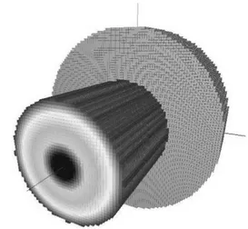
The initial point of the voxelization is the exported CAD model of the component. The volume is divided with the aid of volume elements, the so called voxels. With these voxels, the volume of the component is reproduced. A voxel is the three-dimensional equivalent of a pixel. The geometry is approximated by the combination of the voxels. The accu-racy depends on the size of the voxels. The figure 3 shows the CAD model and the voxelmodel of the flanged steel shaft.
Each volume element is accessible to the user. It is possi-ble in further steps, to link them with information of the component properties.
Fig.3: Component models of the flanged shaft
D. Allocation of the component properties
With the aid of the voxel technology for the component description, it is possible to describe specific points of the component volume. A volume element is chosen and then characteristic properties´ information is allocated in it. This is made for all the relevant positions. The data of the properties, including its position, is saved in a database.
Because of the huge number of voxel, depending on the size of the component model more than thousand, the input of the characteristics of each voxel is very complex. For areas with huge gradients of the characteristics more voxels have to be described than in uninteresting areas of the component. In these areas is merely an indication of the boundary values necessary. The assignment of the characteristics to the un-described volume elements takes place in the next step of the component description.
E. Interpolation of the properties
The interpolation of the characteristics values between the described positions follows the description of the needed positions. Because of the geometry dependency of the components’ characteristics, the interpolation has to respect these. A linear interpolation of four points on a circular geometry would result from the direct connection line of the points. Therefore the characteristics are described by a
rec-tangular, which does not fit the circular gradient expected. To avoid this problem an interpolation method is used, that implicates the geometry in its interpolation. By the use of this algorithm the characterization of the undescribed voxels is possible (figure 4).
Fig. 4: Voxelmodel with interpolated characteristic gra-dient in the stub shaft.
Output of the interpolation phase is a complete described component model. It is described by voxels that are linked to the components’ characteristics. The characteristics are de-pending on their position in the component. To simplify the recognition of the geometry, the application of a fea-ture-recognition is planned. This should help in describing the gradients of the characteristic properties.
For detailing the characteristics additional voxels can be described at any time.
The characteristic gradients of the components properties are visualized by a colour gradient in the component model to make a check intuitive and easy. The visualisation for the properties of the flanged steel shaft is shown in figure 5.
IV. PROTOTYPE OF THE VOXELISATION TOOL
At the moment a prototype of the software tool for the description of functional graded components is developed and programmed.
The tool uses the exported CAD model of the component. First the dimension of the voxels is chosen. For the voxeli-sation an algorithm is used, that takes six two-dimensional recordings of different directions of the imported component model. By a comparison of the recordings, the boundaries of the component are defined. The components’ volume is filled up by voxels afterwards. Thereby a three-dimensional model of the component is generated, where the geometry is copied by the use of cubical elements. The accuracy of the voxel-model is determined through the combination of the voxel dimension and the dimensions of the component.
a) CAD model b) Voxelmodel
Proceedings of the World Congress on Engineering 2009 Vol I WCE 2009, July 1 - 3, 2009, London, U.K.
To enter the properties values, the voxels are directly picked. For assisting the interpolation at the moment the geometry of the components region to describe is manually forced. After the interpolation step, the properties gradients can be visualised by choosing the property that someone wants to see.
Single steps of the component description of functional graded components can be accomplished by the use of the prototype of the voxelisation tool at present. Further steps of the procedure have to be integrated and to be improved, to assure the description of functionally graded components to be accurate. The enhancement of the tool is one of the goals of our work.
V. PROSPECT
To get information about the geometry of the component the use of feature recognition in the process of the component description is targeted. Feature recognition means to check the CAD model for basic bodies. Features are objects, a component can be build of in CAD system. Features are geometrical bodies that can be attached by Boolean operators to build up a component model. Geometrical bodies can be bowls, cubes or special features like a drill hole, a flute or a mating surface. The features can be manipulated in their dimensions and it is possible to decompose components into such basic bodies [6].
The description of functional graded components is used for the development of the manufacturing processes. The information about the geometry as well as the properties of the component is necessary for the planning, because the properties shall be produced integrated in the manufacturing process. This can only be reached when at the beginning of the planning process all gradients of the properties are known before. By using the information about the component for the selection and the validation of the manufacturing technolo-gies, a manufacturing process is developed, which is
de-signed especially for manufacturing of the requested com-ponent properties. In the step of the optimization of the process chain the description of the components properties is used for the evaluation of the process quality.
VI. CONCLUSION
The description of functionally graded components is not possible using todays CAD systems. New description me-thods are needed to describe gradients of properties within the description of functionally graded components. The ex-plained approach for the description of graded components gives the possibility to do so. An uncomplicated way to de-scribe components and to save Information in it is given by the voxelisation. For the further development of the descrip-tion approach the integradescrip-tion of feature recognidescrip-tion is planned.
ACKNOWLEDGEMENT
This work is based on investigations of the Collaborative Research Centre Transregio 30 which is kindly supported by the German Research Foundation (GRF).
REFERENCES
[1] M. Reyes-Perez, J. Gausemeier, D. Nordsiek: “Ontology Development for a Manufacturing Data Base for Products with Graded Properties” in International Conference on Information, Process, and Knowledge Management, 2009. eKNOW '09, pp. 105-109
[2] W. Eversheim, G. Schuh: „Integrierte Produkt- und Prozessgestal-tung“, Springer Verlag, 2004
[3] C. M. Hoffmann: “Geometric and Solid Modeling: An Introduction”, San Mateo, California, Morgan Kaufman Publishers, 1989
[4] E. A. Karabassi, G. Papaioannou, T. Theoharis: “A Fast
Depth-Buffer-Based Voxelization Algorithm”, Journal of Graphics Tools, ACM, Vol. 4, No. 4, 1999
[5] N. Frei: “Neue wissensbasierte Möglichkeiten im Konstruktionspro-zess – Automatisierung des Übergangs der konzeptionellen in die ge-stalterische Phase im Konstruktionsprozess, CAD-FEM Forum, Knowledge-based Eingineering (KBE), Stuttgart, 2003
[6] VDI-Gesellschaft Entwicklung Konstruktion Vertrieb (VDI-EKV): VDI2218 „Informationsverarbeitung in der Produktentwicklung – Feature Technologie“, VDI Richtlinien, 2003
Capture
700 HV
500 HV
350 HV
200 HV
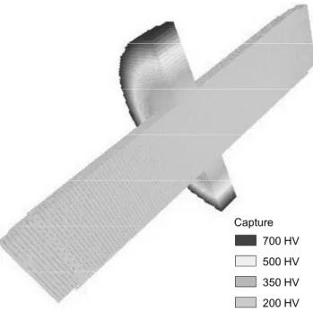
Fig. 5: Voxelmodel of the cut flange steel shaft with visu-alisation of the hardness gradient included
Proceedings of the World Congress on Engineering 2009 Vol I WCE 2009, July 1 - 3, 2009, London, U.K.