Brazilian Journal of Physics, vol. 35, no. 3B, September, 2005 731
Integral System for Detecting Evaporation Residues in Fusion Reactions
O.A. Capurro, J.E. Testoni, G.V. Mart´ı, A. Arazi, J.O. Fern´andez Niello, A.J. Pacheco, Laboratorio TANDAR, Departamento de F´ısica, Comisi´on Nacional de Energ´ıa At´omica,
Av. Gral. Paz 1499 (1650), Partido de Gral. San Mart´ın, Buenos Aires, Argentina
M.E. Ortega, J. Tiffenberg, and M. Fleitas Departamento de F´ısica, Universidad de Buenos Aires,
(1428) Buenos Aires, Argentina
Received on 1st November, 2004
We have designed and constructed an integral system that involves two electrostatic deflectors followed by a small ionization chamber with a multi-wire-proportional-counter in its entrance. The function of the former part is to separate evaporation residues from beam ions using their different electric rigidities while the latter is to detect these evaporation residues being distinguished from the beam-like particles originated in slits. Up to now, both devices have been tested and evaluated performing different experiments: the double-electrostatic deflector through scattering studies and the ionization chamber by means of scattering and fusion reactions. We present a brief description of the two devices and some results obtained in different tests.
I. INTRODUCTION
One way to measure the fusion cross section is just to de-tect the nuclei resulting from the evaporation of the com-pound nucleus. These evaporation residues (ER) are emitted at forward angles and, therefore, they merge with the projec-tiles. Typical rates for projectiles and ER are 1011 and 103 particles per second, respectively; therefore, it is essential to reduce the beam-like particle rate in the detector. Moreover, although this requirement could be achieved, a second diffi-culty is present in any fusion experiment: to differentiate the fusion products from the projectile-like particles originated by slit-scattering and/or multi-scattering in the target.
II. ELECTROSTATIC DOUBLE-DEFLECTOR AND ITS PERFORMANCE
The first problem pointed out in the previous Section has been answered employing recoil separators [1–3] but some li-mitations has to be kept in mind, e.g. low and uncertain effici-ency and –in several cases– restricted angular range. Another possibility has been the use of electrostatic deflectors which can separate ER from projectiles thanks to the very different electric rigidity of ones and the others [4–8]. However, the evaporation residues have a wide range in energy and charge state; thus, in these devices, they are deflected differently and not all of them are finally observed. These features can be seen in Fig. 1a). Here, we show a simple deflector which has a grid as plate. The plotted trajectories were calculated for the system13C +105Pd atE
lab=41 MeV. On the one hand, we can see that the beam is clearly separated from the fusion pro-ducts. On the other hand, it is clear too that the evaporation residues are dispersed over a wide angular range. The two groups shown in the picture correspond to the lowest and the highest energy of the evaporation residues. The wide disper-sion of the evaporation residues can be lowered employing a second electrostatic field –instead a magnetostatic field as in
a Wien filter [9]–. Figure 1b) shows the predicted effect. The direction of the second field is just opposite to the first one. Its function is to correct the more deflected trajectories.
Several devices –employing different insulator materials and designs– were essayed for the double deflector trying to reach high voltages without sparks in the scattering chamber at a pressure of∼10−5Torr. From the literature [10] and our
tests we can conclude that three practical considerations need to be taken into account to attain high voltages without rea-ching the electrical breakdown process: 1) The performance of a vacuum gap is much better than that of a solid insulator of similar dimensions; 2) It is important to have insulator lengths as long as it is possible; 3) The high voltage electrodes have to be mechanically polished and their edges properly rounded. Following these elemental concepts, our last design can reach electric fields of about 15 kVolts/cm without sparks; no pre-vious conditioning is necessary. The anode plates are made of polished aluminium and the cathode grid consists of strai-ned Cu-Be wires (φ=50µm). The length of the device is 31 cm and the distance between each plate and the grid is 3.25 cm. The material used as solid insulator (Nylon) to hold up the electrodes was cleaned with Extran cleanser prior to the assembling.
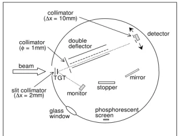
In order to study the performance of the double deflector, we have carried out elastic scattering experiments employing the setup shown in the Fig. 2 where one can see a movable Si detector behind the double deflector in order to search the ions of interest. The12C +natPd system was studied at a bom-barding energy of 30 MeV to detect two kinds of ions: low mass with high energy (projectiles) and medium mass with low energy (recoils). The electrostatic separator was placed at
∼30orespect to the incident beam and both types of ion
732 O. A. Capurro et al.
anode
cathode ER
projectiles beam
TGT
beam
cathode
ER
anode 1 projectiles
TGT
anode 2
a)
b)
FIG. 1: Trajectories of projectiles and evaporation residues for the system13C +105Pd atElab=41 MeV in a simple a) and a double b) electrostatic deflector.
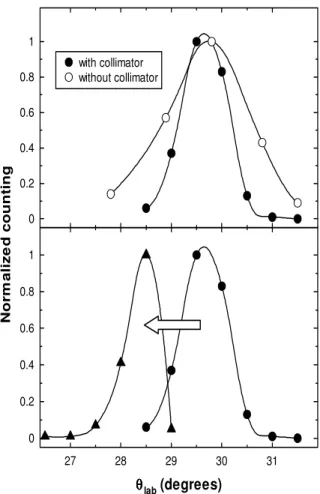
30 kVolts applied on the first and second anode, respectively). A step forward was to evaluate the influence of a 2 mm strip collimator placed close to the target with the aim of reducing the angular variations associated to the beam spot movement. In the upper part of the Fig. 4 we can observe that the FWHM of the angular spread corresponding to the carbon ions is re-duced by a factor∼2. The lower part of the same figure shows
how, using the strip collimator, carbon ions of 29 MeV are dis-placed∼1 degree when an electric field of about 13 kVolts/cm
is applied between the first plate and the grounded grid. The strip collimator allows a good separation of peaks with angu-lar positions differing in one degree.
III. MULTI-DETECTOR
Although the double deflector is able to separate fusion pro-ducts from the projectile ions, it is expected that an important number of projectile-like particles –resulting mainly from slit scattering– arrives at the detector. These ions play a crucial
beam
glass window
monitor
phosphorescent screen
stopper
mirror detector
TGT double deflector collimator
(φ = 1mm)
collimator (∆x = 10mm)
slit collimator (∆x = 2mm)
FIG. 2: Setup used in the elastic scattering experiments carried out in order to study the performance of the double deflector. Some ele-ments associated to the focusing procedure are also displayed.
31 32 33 34 35 36 37
0 0.2 0.4 0.6 0.8 1 1.2
θ θθ θ
lab (degrees)
N
o
rm
aliz
e
d
cou
n
tin
g C
Pd
FIG. 3: Angular distributions of carbon and palladium ions cor-responding to voltage differences of 40 and 30 kVolts between the grounded grid and the first and the second anode, respectively.
role due to the similar energies of these particles compared to those corresponding to the ER ions. Therefore, typical∆E-E telescopes are unsuitable to make out ones and the others re-sulting necessary to measure the time-of-flight of both type of ions.
Brazilian Journal of Physics, vol. 35, no. 3B, September, 2005 733
0 0.2 0.4 0.6 0.8 1
N
o
rm
aliz
e
d
cou
n
tin
g
with collimator without collimator
27 28 29 30 31 0
0.2 0.4 0.6 0.8 1
θ θθ θ
lab (degrees)
FIG. 4: The upper panel shows the reduction of the angular spread caused by the presence of the strip collimator. A satisfactory separa-tion of one degree is achieved using this collimator as can be seen in the lower panel.
anode
Frisch grid
cathode silicon
detector MWPC
Mylar gas
indoor
gas outdoor 80 mm
3 mm
10 mm
40 mm
FIG. 5: Schematic representation of the multi-detector TOFICHE.
determination.
In order to characterize the multi-detector TOFICHE, a va-riety of systems were analyzed by elastic scattering experi-ments combining four projectiles (12C,35Cl,80Se, and127I) with two targets (12C and197Au). Different values of partial loss of energy, residual energy, and time of flight were obtai-ned for the projectile and recoil scattered ions changing the
20 40 60 80 100 120 140
20 60 100 140
Energy (a.u.)
TO
F (
a
.u
.)
fusion
beam-like
elastic 50
100 150
fusion
beam-like
FIG. 6: Time-of-flight vs. residual energy spectra for the 12C(54MeV) +105Pd system. In the upper panel a detailed plot of
the fusion region is shown; in the lower panel, a panoramic picture of the spectrum is displayed.
detection angle. In spite of the good results obtained from these experiments, we believed that the best test of confidence would be given by analyzing a fusion reaction experiment. In order to do this, carbon ion beam delivered by the tandem ac-celerator of the TANDAR Laboratory in Buenos Aires bom-barded an enriched metallic105Pd target. The irradiation was carried out at a bombarding energy of 54 MeV (∼30% above
the Coulomb barrier). The multi-detector TOFICHE was pla-ced at θlab=7.6o and operated with isobutane at a pressure of 4 Torr. Time-of-flight vs. energy spectra obtained for the 12C(54MeV) +105Pd system can be seen in the Fig. 6. The up-per panel of this figure shows clearly that the evaporation resi-dues are differentiated from the projectile-like particles. The spectrum shown in the lower panel gives a panoramic view of the time-of-flight vs. energy plot that includes elastic, beam-like and fusion events. This picture reveals as indispensable the use of an electrostatic deflector in order to avoid that car-bon ions, scattered by the target and slits, overwhelm the site where the evaporation residues must be registered.
IV. SUMMARY AND CONCLUSIONS
electros-734 O. A. Capurro et al.
tatic deflectors instead of a single one. To detect the eva-poration residues we have devised and built a small ioniza-tion chamber from which one can obtain four signals: energy loss, residual energy and two timing signals (start and stop); these two latter signals let us to measure the time-of-flight. Thus, the measurements associated to the energy and the time of flight will allow us to distinguish the evaporation residues from the beam-like particles. Up to now, both devices have been tested and evaluated in several experiments: the double electrostatic deflector through scattering studies and the ioni-zation chamber by means of scattering and fusion reactions.
The good results obtained from all these experiments give us reliance to affirm that both devices can be used in fusion cross section measurements. The natural next step will be try our integral system of detection as a whole.
Acknowledgments
Some of us (JET, JOFN, AJP) are fellows of the Carrera del Investigador Cient´ıfico of the CONICET (Argentina).
[1] K. Suboticet al., Nucl. Instr. and Meth.A 481, 71 (2002) [2] M. Leino, Nucl. Instr. and Meth.B 204, 129 (2003) [3] C.N. Davids, Nucl. Instr. and Meth.B 204, 124 (2003) [4] W.S. Freemanet al., Phys. Rev. Lett.50, 1563 (1983); Phys.
Rev.C 28, 919 (1983).
[5] M. Dahlingeret al., Nucl. Instr. and Meth.219, 513 (1984) [6] S. Beghiniet al., Nucl. Instr. and Meth.A 239, 585 (1985)
[7] R. Schickeret al., Nucl. Instr. and Meth.A 269, 585 (1988) [8] A. Charlop, Lecture Notes in Physics, Springer-Verlag, 317
(1988)
[9] J.X. Weiet al., Nucl. Instr. and Meth.A 306, 557 (1991) [10] R.V. Latham, ”High voltage vacuum insulation”, Academic