Ion-Solid Interaction: Status and Perspectives
Dietmar Fink1 and Lewis T. Chadderton2
1Hahn-Meitner-Institut Berlin, Glienicker Str. 100 D-14109 Berlin, Germany and 2Inst. of Advanced Studies, Australian National University, Canberra, Australia
Received on 3 November, 2004
The past half century has seen an explosive growth of the discipline that is characterized by the deposition of localized high energy densities in solid matter, by means of energetic ions produced e.g. in particle accelerators. First the fundamentals of Ion-Solid Interaction are outlined. A brief overview is given about the basic energy transfer mechanisms and the consequences of ion impact into solids, such as scattering, sputtering and radiation damage. The latter gives rise to numerous changes in the material’s physical and chemical properties, part of which has proven to be detrimental, and part of which is beneficial for technological applications. Though meanwhile a good general understanding of this discipline has been obtained, there are still plenty of lacks of details in our knowledge. Some representative examples are given. As a conclusion of all these points, one may say that, in spite of its age, Ion-Solid Interaction is still a challenging scientifical field, and it still offers lots of promising applications.
I. INTRODUCTION
More than half a century has passed already since the ad-vancement of the field of ion-solid interaction to the state-of art that we know today. A fully developed science has emer-ged since then, and many effects which were just considered as objects of pioneering research just a few decades ago, now belong to the well-established academic material upon which many preparatory or analytic techniques in material’s science are based, or which are even used for commercial applicati-ons. Nevertheless, in spite of all these achievements, there are still astonishingly large gaps to be found in many areas, if one only scratches a little bit deeper below the well-established surface. This represents a challenge as well for those collea-gues working already since long in this area, as for newcomers in this field.
In this paper, a short overview is given about this field and its applications (with some special emphasis on ion-polymer interactions and electronic applications), and thereafter some open questions are posed which still deserve an answer by future researchers.
II. FUNDAMENTALS OF ION-SOLID INTERACTIONS
Sources of Energetic Ions. The basic requirement for per-forming any study in this field are, of course, energetic ions. They can be obtained in many ways, e.g. by making use of radioactive sources such asαparticle or fission product emit-ters, or by exploiting nuclear reactions e.g. with neutrons from a reactor, that result in the emission of protons, tritons,α par-ticles or fission products, depending on the type of irradiated material. Other particle ions become available by bombard-ment of swift heavy ions (SHI) onto appropriate target ma-terials, via various types of nuclear reactions such as fusion reactions, spallation reactions, etc. Finally, for obtaining par-ticles with the highest energies, one even can make use of the sporadically arriving cosmic rays.
The easiest way nowadays, however, to obtain particles with sufficient fluence in a “convenient” energy range of, let
us say, some keV to some GeV, is to produce them in an ap-propriate particle accelerator. There are hundreds of smaller accelerators available in the keV to lower MeV energy range, and nearly a dozen accelerators which provide ionic particles with upper energies of several hundred MeV to a few GeV.
A typical example of the latter ones is the heavy ion accele-rator “ISL” of the HMI Berlin which produces beams of ions ranging from hydrogen to gold, with maximum energies of∼ 70 MeV for hydrogen and∼400 MeV for gold. The maxi-mum charge of the ions is in the order of 26+, and the typical fluences that can be provided with these ions are in the order of 109to 1010 ions/cm2s. In one of the irradiation facilities, the particle beam can be scanned over a maximum area of 3 cm x 3 cm, and targets can be moved across this spot as well horizontally as vertically, thus covering maximum target areas of 30 cm x 30 cmin situ. In another facility, which is devoted to the irradiation of polymer foils, the particle beam can even be scanned horizontally up to±15 cm, whereas the target foil is fed vertically through the scanned beam. In this way, foils of lengths of hundreds of meters can be irradiated in one run. To obtain a good homogeneity of the irradiation, the particle current can be stabilized within±1 %.
Stopping Power[1]. Once an energetic particle beam hits matter, it transfers energy to the latter. In contrast to the in-teraction of, e.g. energetic electrons or photons with matter, the main peculiarity of energetic ion impact is the extremely high localized density of the energy transferred to the target by the particles. In this way, solids may receive for a very short time (∼10−17to 10−15s) within a very tiny volume (∼10−17to 10−16cm3)the same energy density which else is only found in the vicinity of an exploding hydrogen bomb, by the impact of just one energetic heavy ion.
components. Its reciprocal integral defines the projectile’s total range. Both stopping powers increase with increasing energy until they reach a maximum value, and thereafter de-crease. The electronic energy transfer reaches its peak value at energies which are orders of magnitude higher than the nu-clear stopping maximum is.
Light ions at any energy, and energetic heavy ions (with stopping powers in the keV/ ˚A range) deliver much more energy via electronic excitation than by nuclear collisions; for low energy heavy ions (with stopping powers in the eV/ ˚A range) the nuclear energy transfer dominates. The nuclear interactions lead to transfer of kinetic energy to the knock-on target atoms which might be displaced from their original positions (if the transferred energy exceeds the displacement energy), and thus might initiate structural defects (e.g. vacan-cies and interstitials in crystalline materials) or, in the case of molecular targets, their radiochemical destruction, if the trans-ferred energy exceeds the displacement energy.
Only upon very high electronic energy transfer by heavy ions, metallic targets exhibit structural changes due to phase transitions. Electronic energy transfer, if sufficiently small, does not show here any remarkable effect but often plays a dominant role in insulators, where it may lead to the formation of structural defects (e.g. of F centers), to radical formation, to bond breaking, or to the formation of novel bonds. This constitutes the base of radiochemistry with energetic ions.
Since∼20 years there exist well-established computer co-des for the simulation of range and damage distributions in solids even in 3 dimensions, the most known one among them being the ,,TRIM“ code by Biersack (“TRIM” = Transport and Range of Ions in Matter) [2]. In many circumstances these codes have an accuracy of a few percent and therefore will always be of general guidance use - particularly in determi-ning approximate ranges and stopping powers. However, with TRIM for example, many and sometimes dominant secondary effects are not accounted for, including damage annealing, ra-diochemical changes, diffusion, etc. In particular there is no crystallinity, no real point defects, and no free surface, so that a good deal of caution and understanding is called for in more complex projectile/target interactions. Specifically two me-chanisms, particle activated prompt anneal (“PAPA”) and dif-fusion assisted delayed anneal (“DADA”) [3], should always be taken into account upon the impact of energetic ions onto matter, as they are good to explain many seeming disagree-ments between simple predictions and observations, e.g. in minerals.
Whereas the individual nuclear collisions lead to a devia-tion of the projectile’s flight direcdevia-tion from its original one, this is not the case for electronic energy transfer. Hence, for projectiles with dominant nuclear energy transfer, the particles will follow a zig-zag movement until they come to rest. This gives rise to a spatially extended damage distribution. For contrast, projectiles with dominant electronic energy transfer (light ions at any energy, or very swift heavy ions) follow a straight flight path. The damaged zone around that ion trajec-tory is called the “latent ion track”. Typical track lengths of SHIs are in the order of 30 to 130µm; the zone of maximum damage along this track, the so-called “ion track core”, has a
typical radius of 3 to 8 nm. The latter is surrounded by a radial zone of greatly reduced damage of up to∼1/2 µm radius, the so-called “penumbra”.
Ion Radiochemistry of Organic Matter. It appears that different transferred electronic energy densities lead to dif-ferent types of defects, those ones formed after low energy ion impact being less stable than those ones initiated by more energetic ions. Consequently a great part of the electronic damage induced by low energy projectiles at ambient tempe-rature often anneals after the irradiation, so that eventually the more stable but originally much less abundant nuclear de-fects finally dominate, in spite of 10 to 1000-fold more ove-rall energy spent for the electronic energy transfer. This effect vanishes, however, for more energetic projectiles, apparently due to more stable types of electronic defects dominating.
Specifically for polymeric targets, the bond breaking and bond formation effects are known as “chain scissioning” and “cross-linking”. Of special importance is the fact that ion-induced chain scissioning of polymers upon energetic ion im-pact leads to an enhanced etchability of many ion-irradiated synthetic polymers. In other words, etchant attack of such an irradiated polymer foil leads to the formation of nano-or mi-cropores, the so-called “etched tracks”. These pores can have different shapes (cylindrical, conical, hyperboloidal, funnel-like etc.), which can be tailored to some extent by the per choice of the corresponding parameters such as the pro-jectile’s energy transfer, the type of polymer, the type of et-chant, etc. It must be mentioned at this occasion that etched tracks can also be formed in silicon oxides and -oxynitrides, and many minerals such as mica.
Polymers that respond with cross-linking onto ion impact will show a reduced etching rate so that etching leads here to a gradual protrusion of the ion track out of the receeding sample surface. There are other peculiar effects to report, e.g. the ion irradiation of organometals which releases a narrow trail of metal atoms (or oxides, sulfides, etc., depending on the type of material irradiated) along their tracks, which even-tually are electrically conducting. This means, ion irradiation imposes an anisotropy onto the electric properties of such ma-terials. SHI irradiation of polysilanes leads to the formation of SiC rods along the tracks, and SHI irradiation of diamond or fullerite leads to the formation of conducting carbonaceous nanotracks.
III. APPLICATIONS OF LOW ENERGY ION IMPACT ONTO SOLIDS
same method is also applied to make polymer films in space more radiation resistant.) Since recently also the possibility to produce the lithographic masks by ion beams came into the focus of interest, as in this way the typical line-widths of the patterns can be reduced from∼0.4µm for deep UV or∼0.25 µm for electron or X-ray lithography to about∼0.10µm, due to the negligible lateral scattering of energetic ions.
Here, focussed ion beams with computer-controlled po-sitioning may gain an important role, as they also be-come a favoured tool for the production of novel Micro-ElectroMechanical Systems (“MEMS”). For example, cogs, gears and other structures with typical lateral dimensions of a fewµm have been produced by proton beams of a few MeV energy and currents in the order of 1 to 100 pA.
It was found that corrosion protection of metals is possible by means of high fluence irradiation with, e.g. nitrogen ions, thus forming highly resistive surface nitride layers that also withstand tribological load much longer. Also the adhesion of immiscible layers of, e.g. metals and polymers could be incre-ased considerably, by thorough ion beam mixing, or reactive ion implantation, substrate pre-sputtering, or ion-beam assis-ted deposition (“IBAD”) of materials. Furthermore optical ap-plications of low energy ion beams, essentially for waveguide production, have become familiar.
Surface Effects. Both the projectiles and the knock-on tar-get atoms give rise to a number of effects in the surface region of an irradiated target, which are exploited in material analy-sis. If a projectile ion entering a solid is backscattered from a near-surface atom by a large angle collision, its (direction-dependent) energy loss sensitively depends on both the depth of the collision and the target atom mass. Therefore, the so-called “Rutherford Back Scattering” (RBS) technique has be-come one of the favoured analytical methods for determining the composition of solid target and their depth distributions. This technique holds, however, only for heavy target atoms. If instead, the depth distribution of light atoms is of interest, then it is preferable to knock-on these atoms in such a way that they escape from the target through the surface in forward di-rection (which implies that the projectiles must hit the target surface under a non-normal direction). This gives rise to the so-called “Elastic Recoil Detection” (ERD) analysis.
The release of surface atoms by the impact of an energe-tic ion is called “sputtering”. One has to distinguish between nuclear sputtering, that scales with the nuclear energy trans-fer for any target, and electronic sputtering, which takes place above some threshold energy upon the impact of very ener-getic heavy ions onto e.g. metallic targets, or upon the im-pact of an ion of any energy onto insulators. The recording of the mass distribution of sputtered atoms in dependence of the amount of removed surface material and of the position on the sample surface is used in the so-called “Secondary Ion Mass Spectrometry” (SIMS) for the determination of the 3D sample composition. As the impact of highly energetic ions onto molecular insulators does not only release small frag-ments from the very point of impact in a jet-like manner, but also larger fragments and even intact molecules from points more far away via shock-wave mechanisms, this sputter tech-nique has become a well-established method to analyze
com-plex organic matter (Plasma Desorption Mass Spectrometry, “PDMS”).
An effect frequently associated with high energy sputtering is “cratering”, i.e. the formation of a surface depletion in the region of ion impact. Due to a highly complex interaction with the material’s elastic and plastic properties, craters often co-exist with nearby hillocks, and sometimes hillocks have even been observed alone [4]. As the material’s elastic and plastic properties are correlated with the final nanotopological struc-tures in a well-defined way, it has been proposed to establish on this basis a technique to probe the material’s mechanical surface properties in the nanometric scale [4].
Ion beam modification of polymeric surfaces for medical applications has gained importance for various reasons. On the one hand, the material’s biocompatibility can be improved; and on the other hand the irradiation of materials can enhance the bioadhesion, by enriching their surfaces with polar moie-ties, especially carboxyl groups, which seem capable of bon-ding most strongly to living biomass. Anticoagulant drugs such as heparin can be ion-grafted on the surface of protheses of all kinds inserted in the human organism, to avoid clotting of blood on their surfaces. Finally, material surfaces can also be sterilized by ion irradiation.
Applications of high energy ion impact onto solids Applications of Latent Tracks in Solids [4,5]. Latent tracks in solids are not yet applied commercially, however th-ree major possibilities show up for their future use: the ex-ploitation of the material’s radiochemical changes, of struc-tural changes along latent tracks, and the use of ion-induced phase transitions. Radiochemical changes along the ion tracks in, e.g. polycarbonate lead to an increase of –OH and other groups to which protons from the ambient readily bond tran-siently, thus giving rise to a slightly enhanced conductivity. This signifies that such a material acts like a hydrogen sen-sor. SHI irradiation of polysilanes leads, after post-annealing, to the formation of long crystalline silicon carbide needles, which might be used for AFM cantilevers or, after appropri-ate doping, as field emitters. SHI irradiation of organometals produces narrow extended zones of metal (or metal oxide, sul-fide, etc., depending on the type of organometal) precipitates, thus giving rise to (semi)conducting tracks. The latter ones, if produced on top of a silicon wafer, form the so-called “TEMI-MOS” (= tunable electronic material with irradiated organo-metal on semiconductor) structures, the peculiar electronic ef-fects of which our group is just examining and is presented in Fig. 4.
Ion-induced structural changes modify the transport and trapping properties of diffusing impurities along the latent ion tracks, hence also their solubility and diffusitivity. This can be exploited e.g. in filtering and separation technology. Do-ping of latent tracks with electronically active materials (or with their precursors, if some subsequent in-situ chemical re-action follows) would also lead to novel electronic devices. Though this has been suggested already a decade ago [6], it has, however, not yet been realized.
sp2-rich conducting phase, one might construct field emission displays, FETs, or novel types of electronic devices (“TE-AMS” structures = tunable electronically anisotropic materi-als on semiconductors) with them.
Applications of Etched Tracks in Solids [3,4]. Since it was discovered that fossil tracks become visible in rocks af-ter polishing and etching, much use has been made of this by geoscientists in applications to geochronology - - the determi-nation of mineral and therefore rock ages from the chemical etching behaviour, particular the lengths of both spontaneous and induced fission fragment tracks. There are also applica-tions in prospecting work for uranium, and for hydrocarbon deposits in sedimentary basins. More recently so-called T(t) models for track formation and annealing have been used in an attractive effort to extract information on the geothermo-metric history of the lithosphere. Unfortunately it has now been shown, and independently confirmed, that there is a very real influence of an ignored and basic physical feature, namely ambient pressure, on track length shrinkage during annealing -the so-called WVC (Wendt - Vidal - Chadderton) effect [7]. It appears that a fundamental reconsideration of this application must now be carried out. Another major breakthrough was obtained when it was found that most synthetic polymer foils are excellent carrier materials for etched tracks [8]. This inex-pensive and simple method for the detection of energetic par-ticles allowed many poorer fellow scientists from developing countries and their students to contribute with important work to the progress of various disciplines. For example, in dosi-metry etched tracks have become important probes. From the observed track parameters, one can largely deduce the track-forming ion specie and its energy; observed track distributions in, e.g. autoradiographic images allow one to determine the direction and the strength of particle radiation sources. The-refore track recording has also become commonplace in radi-oprotection, medicine, and biology.
Apart from this, many ion track-etched membranes are used in filtration, which is needed for clean rooms, medicine and pharmaceutics, separation technology, and respiration protec-tion. They are also used as inexpensive low-background cat-cher foils for ecological studies. Furthermore, micro- or na-noporous foils are successfully used for hospital treatment of burns and wounds, for gas pervaporation, and in analytical sciences. Ion track-etched membranes are often preferred to simpler and cheaper filter foils, due to their uniform thick-ness, inertness to toxic environments, a high tensile strength, large porosity, nearly unit tortuosity (ratio of the pore length to membrane thickness), and very large sizes.
Only with the onset of interest in nanoscience one started to incorporate matter in etched tracks, to form in this easy way nanowires, nanofibrilles, or nanotubules, shown in Fig. 1. De-pending on the incorporated material, various applications can be obtained. For example, by the grafting of thermoresponsive gels onto the walls of etched tracks one obtains nanovalves that open or close at a preset temperature. This can be used for intelligentin-vivodrug delivery. By addition of, e.g. anatase (a TiO2phase) nanoparticles to the track walls, the tracks de-velop photosterilizing properties which can be used for wound treatment, water purification or packing of food and flowers.
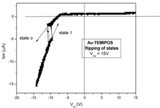
Also the deposition of dispersed (semi)conducting nano-clusters onto the walls of etched tracks make sense, as the choice of the cluster-to-cluster distance determines the layer resistivity within many orders of magnitude from insulating to conducting, and it also allows for various current/voltage and current/temperature correlations of that track-based nanore-sistor, due to the different conductivity mechanisms involved [9]. The incorporation of nanoclusters (of Ag, Au, CdS,. . . ) in etched tracks has been widely applied in the novel “TEM-POS” (= tunable electronic material with pores in oxide on semiconductor) and “TEMIPOS” (= tunable electronic ma-terial with irradiated polymers on semiconductor) structures which stand in their behaviour somewhat in between tunable resistors, capacitors, conventional and Esaki diodes, field ef-fect, bipolar, and unijunction transistors, and sensors, depen-ding on their production and operation parameters, as shown in Figs. 2-4.
Various materials have already been - or still will be - em-bedded in etched tracks that act as nano-sensors for physi-cal (e.g. temperature, pressure, light intensity, magnetic field intensity,. . . ), chemical (e.g. moisture, alcohol, acetone, su-gar, . . . ), or biological (germs, viruses, hormons, enzymes, . . . ) parameters. Checkerboard-like contacting on both sides of such a suitably treated microporous foil will enable one in future to perform 2D mapping of the required sensor signals.
By sandwiching the track-forming material with layers of other materials (e.g. producing a Si-polymer bilayer struc-ture), by multiple sequential axial or radial material deposi-tion into etched tracks, and by combinadeposi-tion with other well-known procedures such as metal evaporation onto the surfa-ces of these microporous foils, one can produce highly com-plex structures which may serve as micro- or nanocondensors, micromagnets, GMR structures, diodes, FETs, LEDs, TEM-POS structures, nanosensors that discriminate several species simultaneously, optical filters, etc.
IV. PERSPECTIVES OF ION-SOLID INTERACTION
Within the past half century the field of ion/solid interac-tion has been pretty well developed, and quite a number of applications has been found. But even now many details are still lacking, which is considered as a challenge for the sci-entists of the next 50 years. Below there are given just a few examples.
There exist elaborate theories on the electronic stopping power [1,3]. However, more complicated cases, involving e.g. the collision parameter dependence and channelling effects, have not yet been treated analytically[11].
FIG. 1: Two examples of tubules in etched tracks. Left picture: Chemically deposited silver layer on walls of double-conical tracks and on the surface of a microporous PI foil; side view. Right picture: CdS/PEO composite layer covering etched tracks in PET, and the foil surface.
FIG. 2: top: Principle of a TEMPOS structure, below: view of Ag nanoclusters deposited onto a microporous SiO2on Si.
sublattice is almost totally protected against energy transfer. Hence the anionic sublattice accepts nearly all the electroni-cally transferred energy, and consequently all the radiation da-mage [7]. In such cases, specifically in alkali and alkali earth halides, the Bragg Rule is completely violated, even with the advanced “CAB” model [10] incorporated. Finally, there have hardly ever been performed detailed measurements on the in-fluence of directional effects in crystals on the electronic stop-ping power of SHIs.
What happens upon ion/solid interaction, when the target size approaches zero? Collision cascades in small targets, such as free-standing or embedded nanoparticles, will behave completely different from cascades in semi-infinite matter for which well-established computer codes exist since long [2]. Surface effects will dominate and probably lead to enhanced sputtering. The increased phonon scattering at the particle boundaries should give rise to higher damage, but, on the other
FIG. 3: V/I characteristics of a TEMIPOS structure (Au nanoclusters in etched tracks in photoresist on silicon). Shown here for a working point in which flipping between two different curves takes place. The curve shows that locally negative differential resistances occur.
hand, the larger and close surface area of such particles should act as a sink for defects that will anneal easier. Diffusing spe-cies should readily be trapped at the particle surface so that one should expect a gettering effect of the particle environ-ment.
Pronounced and beautiful craters have been observed after swift heavy ion impact onto insulators. It is, however, not yet known whether also keV particle impact onto insulating surfaces (e.g. of polymers) results in cratering.
Impedance Spectroscopy is a well-established field in elec-trical engineering. It is convenient to depict both the fre-quency dependent resistance R(ω)and the capacitance C(ω) of a material in the complex plane via: Z = R(ω)– i X(ω), with X(ω)= [ωC(ω)]−1. (Specifically for the complex dielec-tricity coefficientε=ε’- iε” of dielectric materials, one ob-tains in this way the famous “Cole-Cole plot“.) Usually one finds semicircles or straight lines in these diagrams which can be modelled with corresponding equivalent circuits. Never such a Cole-Cole plot has been determined for ion-irradiated matter.
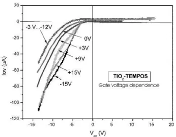
pro-FIG. 4: Current/voltage characteristics of a TiO2-TEMPOS struc-ture. In this peculiar case, the gate voltage influences only the third quadrant. Interestingly, both high positive and negative gating vol-tages change the current/voltage characteristic in the same way, but lower gating voltages do not. Photocatalytic effects (not shown here) change only the curve in the first quadrant and remain nearly unaf-fected by the gating signals.
cess of non-soluble high-dose implants, e.g. of metals in a polymer. Also the subsequent radiation-induced cluster redis-tribution has hardly been observed.
Radiobiological questions become only now of interest, such as the adsorption and desorption of biological species on ion-irradiated surfaces. Also there is a lack of good infor-mation on the sterilizing properties of ion-irradiated surfaces. Radiochemical mechanisms after ion impact have been worked out only for the most common synthetic polymers. Nearly nothing is known, however, about corresponding re-actions in e.g. elastomers, biodegradable synthetic polymers,
“living” polymers, and organometals.
Ion-induced polymerization and depolymerization proces-ses in both solids and liquids have hardly been treated.
The very promising development of ion-track-based sen-sors has only now just begun. There is a great demand for hou-sehold, cars, ecology, chemical industry, medicine, and ABC antiterror protection. The same holds for actuators, to create self-regulating intelligent systems in the above-mentioned fi-elds.
As a conclusion, one might say that the field of ion-solid in-teraction, a former spin-off from nuclear science, is now a well established science with good fundaments and useful applica-tions emerging. However, due to the relatively short life time of that science, many details are still unknown. Therefore, ion-solid interaction is still now regarded as a challenging sci-entific field that offers still lots of promising applications, and it justifies especially the invitation to interested scientists from other fields to contribute to this discipline with their great spe-cific expertise.
Acknowledgments
We are especially indebted to our friends J. P. Biersack, A. Berdinsky, M. Behar, V. Hnatowicz, J. Vacik, M. M¨uller, and K. K. Dviwedi, for their expertise and continuous help and assictance in our work in the field of ion/solid interac-tion. We also want to extend our thanks to our dear colle-agues R.M.Papaleo, W.R.Fahrner, K.Hoppe, and A.Chandra who contributed to many of the results reported here. Warm thanks also to our former PhD students and PostDocs T.Kie, L.Wang, R.Klett, P.Goppelt-Langer, A.Petrov, P. Fichtner, P. Grande, R. Kaschny, P. Alegaonkar and D. Sinha, and to many other helpful colleagues, unfortunately remaining unnamed here for the lack of space. This work was enabled by the kind assistance of M. Tabacniks and J. Chubaci, and by funds of the Sociedade Brasileira de F´ısica, Sao Paulo, Brazil for D.F.
[1] U. Littmark, J. F. Ziegler, “Handbook of Range Distributions for Energetic Ions in All Elements”, Vol. 6, Pergamon Press, New York (1980), and: J. F. Ziegler, ”Handbook of Stopping Cross Sections for Energetic Ions in All Elements”, Pergamon Press, 1980, and: J. F. Ziegler, J. P. Biersack, U. Littmark, Pro-ceedings of the USJapan Seminar on Charged Particle Penetra-tion Phenomena, ORNL report CONF820131 (1982), p.88 [2] J. P. Biersack, L. G. Haggmark, The Transport and Ranges in
Matter.Nucl Instr Meth174, 257 (1980).
[4] L. T. Chadderton and D. Fink, Fullerene Genesis by Ion Be-ams III. On the Absence of Latent Tracks in GeV Ion Irradiated Graphite. Rad Effects Def. Solids152, 87 (2000).
[4] for more details, the reader is referred to modern textbooks, e.g. to:Transport Processes in Ion Irradiated Polymers and Appli-cations, Vols. 1 and 2, D. Fink (ed.), Springer-Verlag (2004) [5] D. Fink, P. S. Alegaonkar, A. V. Petrov, A. S. Berdinsky, A. V.
Rao, M. M¨uller, K. K. Dwivedi, L. T. Chadderton, The
Emer-gence of New Ion Track Applications, Radiat. Meas.36, 605 (2003).
[6] D. Fink, R. Klett, Latent Tracks in polymers for future use in nanoelectronics, an overview about the present state-of-the-art. Braz. J. Phys.25, 54 (1995).
[7] A. S. Wendt, O. Vidal, and L. T. Chadderton, Earth and Planet Sci Lett.,201, 593 (2002).
[8] R. L. Fleischer, P. B. Price, R. M. Walker, Nuclear Tracks in Solids: Principles and applications. University of California, Berkeley, 1975
[9] S. M. Sze, Physics of Semiconductor Devices. J.Wiley Sons, New York, 2nded. (1981)
[10] J. F. Ziegler, J. Manoyan, The stopping of ions in compounds.
Nucl. Instr. MethB35, 215-228 (1988)