446 Brazilian Journal of Physics, vol. 37, no. 2A, June, 2007
Digital System to Characterize Solid State Nuclear Track Detectors
F. Pugliesi, V. Sciani, M.A. Stanojev Pereira, and R. Pugliesi Instituto de Pesquisas Energ´eticas e Nucleares (IPEN-CNEN/SP),
Av. Prof. Lineu Prestes 2242 Cidade Universit ´aria, Butant˜a, CEP 05508-000, S˜ao Paulo, SP, Brazil
Received on 14 February, 2007
A digital system to characterize solid state nuclear track detectors(SSNTD) has been developed. It was used in the study of two detectors and its performance evaluated by comparing the obtained results with those determined by using an analog system, already in use for such purpose. The comparison of the results together with the feasibility and rapidness in data acquisition have demonstrated the viability of the digital system to characterize SSNTD.
Keywords: Track detectors; Track - etch foils; Radiation detection
I. INTRODUCTION
Heavy charged particles passing through dielectric solids leave a narrow and permanent trail of damages with diame-ter of about 100 Angstrons and length equal to the range of the particle in the solid. Under an adequate chemical etch-ing the damaged regions, beetch-ing more reactive than the sur-rounding undamaged areas, are enlarged and form permanent tracks which may be seen in an optical microscope. These solids are known as nuclear track detectors (SSNTD) and the more common commercial include the polycarbonates (MK-E; MK-DE), the polyallyldiglycol carbonate (CR-39) and the cellulose nitrates (CN-85, LR-115). These detectors are ap-plied in different branches of science such as in the hole en-gineering, micro-pore membrane technology, nuclear physics, dosimetry, radiography and earth sciences [1,2].
The interpretation of the information registered in a SSNTD requires the characterization of some specific parameters such as the track growth rate, track production rate and exposure interval for optimal contrast, as functions of the irradiation and etching times [3,4].
The objective of the present paper is to describe and eval-uate a digital system developed by the neutron radiography working group of the IPEN-CNEN/SP for SSNTD character-ization. Its performance has been checked by comparing the results from the characterization of two conventional SSNTD with those determined by a standard analog system.
II. EXPERIMENTAL
The irradiations have been performed in a neutron radiog-raphy facility installed at the radial beam line 08 of the 5MW IEA-R1 Nuclear Research Reactor which provides an uniform neutron beam at the sample irradiation position. Its main char-acteristics are given in Table I [5].
During the irradiation, the detectors and a converter screen, are kept in close contact inside an aluminum cassette. The selected detectors were MK-E and MK-DE manufactured by Bayer AG with thickness of 100 µm and 500 µm respec-tively. The converter screen is a plastic backing, single coated with a natural boron layer (65 µm thick), produced by Ko-dak Path`e (French). In this case, the damages inside the
detectors are induced by the products of the nuclear reac-tion10B(n,α)7Li(α-energy=1.47MeV; Li-energy=0.84MeV). After irradiation, the detectors are etched in a KOH (15%), ethanol (40%) aqueous solution (PEW solution) at 70 ˚ C con-stant temperature [1].
TABLE I: Characteristics of the neutron beam at the sample irradia-tion posiirradia-tion
Neutron flux (n.s−1.cm−2) 1.75x10⁶ Beam diameter (cm) 20 Mean Energy (meV) 7
The digital system, shown in Fig. 1, consists of two sub-systems. The first, designed to evaluate the transmitted light
photo enlarger
light source
condenser
screen video camera
computer
video camera
microscope
Sub-system 1 Sub-system 2
detector position
FIG. 1: Sketch of the digital system.
F. Pugliesi et al. 447
of RAM). The light intensity is evaluated in a 8 bit gray level scale ranging from 0 (the darkest pixel) to 255 (the bright-est one). The second sub-system designed to evaluate track size and track density consists of an optical microscope (Leitz) having maximal magnification power of 1500x, with an ana-log video camera (Burle model TC651B) used to capture the magnified image. The digitizing as well as the image process-ing are performed by usprocess-ing the same computer and software mentioned above [6].
III. DATA ACQUISITION AND ANALYSIS
A. Track growth rate
The track growth rate was determined through the behav-ior of the track diameter as a function of etching time. In order to minimize track overlapping, which leads to false di-ameter evaluation, the neutron exposure was set as low as E∼2x10⁷n.cm−2corresponding to an irradiation of about 10 seconds. The neutron exposure is given by E =φ.t where “φ” is the neutron flux (n.s−1.cm−2)and “t” the irradiation time
(s). After irradiation, the detectors were etched and individual tracks magnified 1500x can be observed. After some image processing to define the track border (High Gauss filter) and to enlarge its original size (zoom 16x), the diameters are de-termined by measuring the linear distance between two dia-metrically opposed pixels, see Fig. 2, by using a previously calibrated length scale. Fig. 3 shows the behavior of diame-ters for MK-E and MK-DE as a function of etching time. Each value has been determined by averaging the diameters of ten individual tracks and the error bars are the standard deviation of the mean. The track growth rate corresponds to the slope of the straight line fitted to these data and the results for both detectors are given in Tables II and III.
diameter
1Pm
FIG. 2: Digital image of a single track: optical magnification 1500x; High Gauss filter; zoom 16x.
0 5 10 15 20 25
1 2 3 4 5 6 7 8 9 10
MK-DE MK-E
tr
ack diam
eter(
P
m)
etching time(min)
FIG. 3: Behavior of the track diameter as a function of the etching time.
B. Track production rate
This parameter is defined as the maximum value of the track to neutron conversion ratio and is determined by the slope of the straight line fitted to experimental data relating track den-sity (track/cm2) vs neutron exposure (n.cm−2). In order to
determine this value it is necessary to obtain the etching time for which the track density is maximum. This was performed by evaluating the behavior of the track density as a function of etching time. Several strips of detector were irradiated at a same neutron exposure E = 6x10⁷n.cm−2and after etching the
detectors were inspected by optical magnification of 1500x which corresponds to an area of about 7,000µm2covered by
the tracks. After a digital processing that transforms tracks to dots, the tracks are automatically counted by the software. The behavior of the track density as a function of the etching time is shown in Fig. 4, where each data has been obtained by averaging the densities of five distinct areas and, the error bars
0 5 10 15 20 25
4x10⁵ 5x10⁵ 6x10⁵ 7x10⁵ 8x10⁵ 9x10⁵
MK-DE MK-E
tra
c
k
d
e
n
s
it
y
(tr/c
m
2 )
etching time(min)
448 Brazilian Journal of Physics, vol. 37, no. 2A, June, 2007
TABLE II: Results obtained by using the digital and analog systems for MK-E
MK-E Digital system Analog system
Diameter growth rate(µm/min) 0.33±0.01 0.33±0.02 Track production rate(track/neutron) 0.0095±0.0006 0.0093±0.0004 Exposure interval(n.cm−2)
Exposure ratio
1x10⁸<E<3x10⁹ 30
1x10⁹<E<2x10¹⁰ 20
TABLE III: Results obtained by using the digital and analog systems for MK-DE
MK-DE Digital system Analog system
Diameter growth rate(µm/min) 0.29±0.01 0.29±0.01 Track production rate(track/neutron) 0.0106±0.0008 0.0114±0.0005 Exposure interval(n.cm−2)
Exposure ratio
2x10⁸<E<8x10⁹ 40
1x10⁹<E<3x10¹⁰ 30
correspond to the standard deviation of the mean. As can be observed the maximum track density for both detectors was achieved at 6 minutes and this result can be interpreted as fol-lows. The greater the etching time, the greater the track depth along the trail of damages and after 6 minutes the track depth is about 7µm. Since this value is approximately the range of the 1.47 MeV alpha particles in polycarbonates, the eval-uated etching time for maximum track density is consistent with the track formation theory, according to which the high-est damage density is produced at the end of the trail where the stopping power is maximum [1, 7].
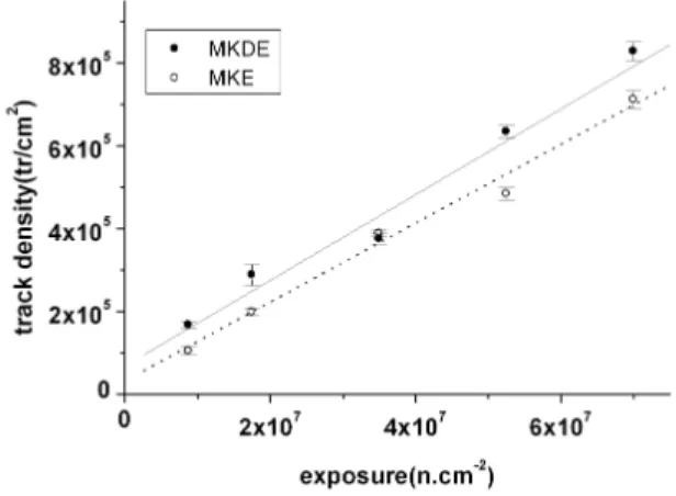
In order to determine the track production rate the detectors were irradiated in several neutron exposures and etched for 6 minutes. The images of the tracks were captured at a magni-fication of 600x and after the same digital processing to trans-form tracks to dots, the tracks were automatically counted by the software. The behavior of the track density as a func-tion of the neutron exposure is shown in Fig. 5. Each data was obtained by averaging the densities of ten distinct areas and the error bars correspond to the standard deviation of the mean. The track production rates obtained for both detectors are given in Tables II and III.
FIG. 5: Behavior of track density as a function of the exposure for 6 minutes of etching.
C. Exposure interval
A characteristic curve relates gray level intensity (GL) as a function of the neutron exposure (E). It is very important for applications involving light transmission evaluation because it defines the exposure interval for which the maximum optical contrast in the image is achieved [8]. In order to determine this curve the detectors were irradiated in the exposure inter-val 3x10⁷<E<3x10¹⁰ n.cm−2. After 6 minutes of etching they were positioned in the photo enlarger and the gray level corresponding to each detector was determined by using the same software averaging the intensity of about 1700 individ-ual pixels, corresponding to an area of 0.4cm2of the detector. The gray level behavior as a function of the exposure is shown in Fig. 6.
FIG. 6: Behavior of the transmitted light intensity as a function of the exposure for 6 minutes of etching.
The neutron exposure intervals for which the optical con-trast is maximum, that corresponds to the steeper region of these curves (shown by arrows), were 1x10⁸< E < 3x10⁹
n.cm−2and 2x10⁸<E<8x10⁹n.cm−2for E and
MK-DE respectively. For these intervals the exposure ratios are 30 and 40. These data are also given in Tables II and III.
F. Pugliesi et al. 449
digital system has been evaluated by comparing the obtained values for the studied parameters with the ones previously de-termined by using an analog system. The analog system was used as reference because it has been employed in IPEN – CNEN/SP to characterize SSNTD, providing reliable and con-sistent results for these same parameters [9,10,11,12].
In this system the same microscope mentioned in section II, is used for the track diameter and track density evalua-tion. The diameters are determined by measuring its apparent value, in a millimeter scale, by using an ordinary plastic rule and the densities by visual counting, both on the screen of a TV monitor.
The light transmissions are evaluated by using an optical microphotometer in which a narrow (3µm x 700µm) and col-limated light beam impinges the detector and the transmitted light intensity is evaluated in an optical density (OD) scale ranging from 0 to 2, corresponding to incident unattenuated light beam and to a transmission of 1% respectively [13].
The Tables II and III summarize the results obtained from both systems.
IV. CONCLUSION
By comparing the obtained results with those obtained from the analog system, the following conclusions can be drawn:
- the diameter growth rate as well as the track production rate for MK-E and for MK-DE, are in agreement within their uncertainties.
- the exposure ratios are 50%(MK-E) and 33%(MK-DE) greater for the digital system meaning a higher exposure in-terval for which the contrast remains maximum.
- the exposure intervals for maximum contrast are reached
in a lower exposure for the digital system. According to data it is 10 times smaller for MK-E and 5 times smaller for MK-DE respectively, indicating lower irradiation times.
The feasibility and the time spent to perform the measure-ments were other important aspects considered in the compar-ison:
- while in the analog system a transparent plastic rule is used to evaluate the apparent track diameter on a TV monitor screen, in the digital the diameter is determined by measuring the distance between two diametrically opposed pixels posi-tioned on the border of a sharp and enlarged image in a PC monitor screen.
- the evaluation of the track production rate involves the counting of about 60 distinct areas each one having 250 tracks typically. In the analog system the counting is visually per-formed and takes at least 5 hours of continuous work but be-cause of the severe visual stress will correspond to an actual time of about 15 hours. In the digital system the same count-ing is performed by the software within about 10 minutes.
- regarding the light transmission measurements, each gray level intensity and its corresponding uncertainty are evalu-ated by averaging the intensities of about 1700 individual pix-els inside an area of about 0.4 cm2. This procedure takes a few seconds. For the microphotometer the same procedure takes about 30 minutes inside an area approximately 200 times smaller.
The numerical agreement of the selected parameters as well as the feasibility and the smaller time spent to perform the measurements demonstrate the convenience of the present digital system to characterize SSNTD. Finally, the easiness to make it operational should be also mentioned. Except for the optical microscope, all the other components are standard, making this system accessible to any laboratory.
[1] S.A. Durrani, R.K. Bull,Solid State Nuclear Track Detection. Principles, Methods and Applications. International Series in Natural Philosophy vol-111. Pergamon Press (1987).
[2] D. Nikezic, N. K. Yu, Mat. Science and Engineering R46, 51 (2004).
[3] R. Ilic’ and M. Najzer, Nucl. Track Radiat. Meas. 17, 453 (1990a).
[4] R. Ilic’ and M. Najzer, Nucl. Track Radiat. Meas. 17, 475 (1990d).
[5] R. Pugliesi, M.L.G. Andrade, M.A.S. Pereira, and F. Pugliesi, Nuc Instruments and Methods A542/1-3, 81 (2005).
[6] V. Sciani, F. Pugliesi, M.A.S. Pereira, and R. Pugliesi, 28 ˚ Meeting on Nuclear Physics in Brasil. 07-11/09, 2005,
Guaruja/SP, Brazil (2005).
[7] http://physics.nist.gov/PhysRefData/Star/Text/contents.html [8] P. von Der Hardt, H. Roettger,Neutron Radiography Handbook.
Nuclear Science and Technology, Dordrecht, D. Reidl (1981). [9] C.P. Meire, MSc thesis. IPEN-CNEN/SP (1992).
[10] E.C. Vilela, MSc thesis. IPEN-CNEN/SP (1990).
[11] M.P.M. Assunc¸˜ao, MSc thesis. IFUSP, University of S˜ao Paulo (1992).
[12] M.A.S. Pereira, MSc thesis. IPEN-CNEN/SP (2000).