UNIVERSITY OF BEIRA INTERIOR
Engineering
Persistent Gliding Waterframe
The Waterframe Conceptual Project
João Paulo Salgueiro Morgado
Thesis submitted for the degree of Master of Science in
Aeronautical Engineering
(2nd Cycle of Studies)
Supervisor: PhD Miguel Ângelo Rodrigues Silvestre
"Try to become not a man of success, but try rather to become a man of value"
Acknowledgments
There are many people whom I would like to thank for helping me over the last year in my research and studies that have made this thesis possible. These people have helped me in the classroom, in the laboratory and in all of the general day to day tasks that have occupied my time.
First, I would like to thank to my supervisor, PhD Miguel Silvestre for allowing me the opportunity to work with you. I would like to thank the fact that you received me in your house every week for skype meetings with UST's team. I was always made to feel comfortable and welcomed and I enjoyed each and every interaction I had with you.
Further, I would like to thank those whom I worked with during the project. This obviously includes the University of Saint Thomas team: the professor Christopher Greene, the students Josh Kleven, Matthew Deutsch, Sean Engen, Frances Van Sloun, Jim Giancola, and JB Korte and at last but not the least Engineer Scott Morgan for the opportunity that he gave me to participate in an international project and for everything I learned as a result.
At the same time, I would like to thank to all my friends, especially to Christian, Miguel, Tiago, Joaquim, Ricardo, Luís, Carlos and Andreia for the friendship, kindness, patience and constant support, never letting me give up.
I would also like to thank to laboratory technician, Mr. Rui Paulo, for all the support that you gave me during the prototype construction.
Finally and most importantly, I would like to thank to all my family, especially to my parents and my sisters for everything you did for me and for helping me keep it all in perspective.
Thank You
Abstract
Underwater gliders are autonomous vehicles that profile vertically by controlling buoyancy and move horizontally due to its wings.[14,17] At the top of a bounce, the glider decreases its buoyancy, which causes it to begin to sink. As the glider sinks, the hydrodynamic shape of the exterior (waterframe design) produces horizontal motion. The gilder uses a method of control to adjust pitch and roll as it continues forward. At the bottom of a bounce, the glider becomes more buoyant, which causes it to begin an upward path. Again, horizontal motion is produced by the shape of the waterframe and mainly by wings. When the glider reaches the surface, it will communicate with a ground station, sending out the data it collected during the dive and receiving instructions for its next trajectory.[5]
This type of vehicles can operate over long ranges and are relatively low cost [2] ocean research vehicles, making them the ideal choice for locate potential areas in the ocean that would be suitable for sea farming. The PGW will be equipped with sensors that will monitoring the underwater environment. The data collected from the PGW will help researchers monitor the fish population and even implement sea farming.
The driving customer requirements for the PGW include a four-month continuous operational runtime, the ability to produce a lower cost system than the current competitors, a two-year useful life before refitting, the ability to launch and recover the PGW from a boat or a dock, the ability to reach a maximum depth of 300 meters, the ability to navigate within 1000 meters of the PGW’s intended course, and all fluids contained in the PGW must be biodegradable.
This thesis presents the development of the waterframe for small ( , long) autonomous underwater vehicle with operating speeds about and ranges up to . A half scale prototype was built and performance tests need to be done to evaluate waterframe's performance.
Keywords
AUV, glider, PGW, Persistent Gliding Waterframe, Autonomous glider, underwater vehicle, waterframe design, sea measurements
Resumo
Os planadores subaquáticos são veículos autónomos que se deslocam verticalmente controlando a sua flutuabilidade e se movem horizontalmente devido à presença de asas.[14,17] Quando se encontram à superfície, o planador diminui a sua flutuabilidade, o que faz com que comece a afundar. Enquanto o veículo afunda, a sua forma exterior produz movimento horizontal. O veículo usa um controlo para ajustar o ângulo de picada e de rolamento para se continuar a deslocar na trajectória correcta. Quando o planador atinge o ponto de profundidade máxima, começa a ficar menos denso que a água que o rodeia e mais uma vez a sua forma exterior e principalmente as asas, fazem com que se desloque horizontalmente. Quando regressa à superfície, o planador subaquático pode comunicar com a estação de controlo enviando os dados recolhidos durante o mergulho anterior e receber informações para o próximo mergulho.[5]
Os planadores subaquáticos podem operar durante longos períodos de tempo tendo por isso um grande alcance e um custo de operação relativamente baixo [2], fazendo com que sejam a escolha ideal para identificar, nos oceanos, potenciais locais para aquacultura. O veículo será equipado com sensores que monitorizarão o ambiente subaquático. Os dados recolhidos pelo planador ajudarão os investigadores a monitorizar os cardumes e a implementar a aquacultura.
Os requisitos do cliente para o PGW incluem 4 meses de operação contínua, a capacidade de produzir o veículo a um custo inferior ao dos concorrentes, a capacidade de operar em oceanos, 2 anos de vida útil antes de manutenção, a capacidade de poder ser depositado na água através de um barco ou de uma doca, a capacidade de chegar aos de profundidade, a capacidade de navegar com um erro máximo de em relação à trajectória definida previamente e ainda o facto de todos os fluidos contidos no PGW terem de ser obrigatoriamente biodegradáveis.
Esta dissertação apresenta o desenvolvimento de uma plataforma para um veículo subaquático autónomo, pequeno ( de comprimento) com velocidades de operação de cerca de e alcance de cerca de . Foi ainda construído um protótipo a metade da escala e é necessário efectuar testes para avaliar a performance da plataforma desenvolvida.
Palavras-chave
Veículo Autónomo Subaquático, Planador, PGW, Planador autónomo, veículo subaquático, projecto conceptual, medições, oceano
Resumo Alargado
Esta tese surgiu no âmbito de projecto com um propósito específico: identificar, nos oceanos, potenciais locais para aquacultura. Esta forma de produção de alimento disponibiliza algumas das proteínas essenciais ao ser humano. O veículo resultante deste projecto estará equipado com um sensor óptico que contará o número de algas numa dada área do oceano. As algas encontram-se na base da cadeia alimentar oceânica e a sua contagem permite que os investigadores estimem e consigam controlar a população de peixes num dado local, ao mesmo tempo que permite ainda que consigam prever mais facilmente mudanças nos cardumes ao longo do tempo. Os dados recolhidos por este veículo irão ajudar os investigadores a implementar a aquacultura.
Os planadores subaquáticos podem operar durante longos períodos de tempo tendo por isso um grande alcance e um custo de operação relativamente baixo, fazendo com que sejam a escolha ideal para a tarefa descrita no parágrafo anterior. O princípio de operação dos planadores submarinos é ilustrado na Figura 1. Nesta figura é ilustrado um ciclo completo de operação de um veículo deste tipo.
Figura 1 - Esquema de operação de um planador subaquático. [5]
Os planadores submarinos utilizam alterações da sua flutuabilidade para se conseguirem deslocar no plano horizontal. Para o veículo começar a descer fica ligeiramente mais denso que a água que o rodeia e ao iniciar o movimento descendente as asas começarão a produzir sustentação, o que impulsionará o veículo para a frente. Ao atingir a profundidade máxima, o planador fica ligeiramente menos denso que a água que o rodeia, para assim começar uma trajectória ascendente.
Devido à sua forma de converter o movimento vertical em movimento horizontal, os planadores subaquáticos têm um tipo de trajectória muito característica, sendo parecida com uma onda sinusoidal. Quando o veículo retorna à superfície pode então comunicar com a
O trabalho desenvolvido nesta tese de mestrado resulta do trabalho desenvolvido no 1º ano do projecto cujo principal objectivo foi projectar conceptualmente a plataforma que albergará todos os sistemas e sensores necessários à operação do veículo.
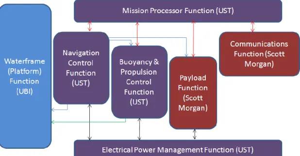
Todo o trabalho foi desenvolvido em cooperação com a equipa da Universidade de Saint Thomas, nos Estados Unidos da América e com o Engenheiro Scott Morgan, sendo estes responsáveis pelo resto dos subsistemas presentes na Figura 2.
Figura 2 - Diagrama de funcionamento do projecto do PGW.
O trabalho desenvolvido nesta dissertação está, como se pode observar, na parte da
"Platform Function", ou seja, desenvolver uma plataforma que consiga albergar todos os
sistemas necessários ao desempenho da missão.
Como este é um projecto a 5 anos, dos quais este foi apenas o 1º, o objectivo principal passou por um projecto conceptual com a adequada selecção dos conceitos aplicáveis, passando pelo cálculo de um ponto de projecto e depois pela definição geométrica do veículo em si. Foram ainda calculados os coeficientes de estabilidade do veículo, para permitir o estudo do seu controlo e estabilidade.
No final obteve-se uma plataforma optimizada, que cumpria os requisitos do projecto e foi ainda construído um protótipo a metade da escala para testes de performance a efectuar futuramente em piscina.
Table of Contents
Acknowledgments ... v Abstract ... vii Keywords ... vii Resumo ... ix Palavras-chave ... ix Resumo Alargado ... xiTable of Contents ... xiii
List of Figures ... xvii
List of Charts ... xxi
List of Tables ... xxiii
Nomenclature ... xxv 1 - Introduction ... 1 1.1 Motivation... 1 1.2 Objective ... 1 1.3 Overview ... 2 2 - Bibliographic Review ... 3 2.1 Underwater Vehicles ... 3 2.1.1 History ... 3
2.1.2 Underwater Gliders - A particular type of underwater vehicles ... 5
2.1.3 Applications ... 6
2.2 Competing Products Review ... 7
2.2.1 Spray ... 7 2.2.2 Slocum Battery ... 9 2.2.3 Slocum Thermal ... 11 2.2.4 Seaglider ... 12 2.2.5 ALBAC ... 13 2.3 Airfoil Design ... 15 2.3.1 Airfoil Geometry ... 15
2.3.3 Airfoil Design philosophies ... 17
2.4 Wing Geometry ... 18
2.4.1 Aspect Ratio ... 18
2.4.2 Wing Sweep ... 18
2.4.3 Wing Taper Ratio ... 19
2.4.4 Wing Incidence ... 19
2.5 Low Drag Shapes ... 20
2.5.1 Axisymmetric Bodies ... 20
3 - Customer Requirements ... 23
4 - Problem Definition and Concepts Identification... 25
4.1 Dive and Climbing - problem ... 25
4.1.1 Symmetric Airfoil ... 25
4.1.2 Fixed Camber Airfoil ... 26
4.1.3 Concept Selection ... 26
4.2 Body Shape ... 26
4.2.1 Flying Wing ... 26
4.2.2 Torpedo Shaped Fuselage ... 27
4.2.3 Concept Selection ... 27
4.3 Wing Vertical Position ... 27
4.4 Stability ... 27
4.4.1 Longitudinal Stability ... 28
4.4.2 Lateral-Directional Stability ... 28
4.4.3 Concept Selection ... 28
4.5 Waterframe Control ... 28
4.5.1 Tail Position Change ... 28
4.5.2 Wing Incidence Change ... 30
4.5.3 Concept Selection ... 30
4.6 Buoyancy Volume ... 30
4.7 Materials ... 31
4.7.1 Metals ... 31
4.7.3 Fibers Reinforced Plastic ... 31 4.7.4 Material Selection ... 32 5 - Design Point ... 33 5.1 Spreadsheet Implementation ... 33 5.2 Glide Ratio ... 35 5.3 Wing Size ... 39 5.4 Airfoil Design ... 41 5.5 Tail Sizing ... 45
6 - Critical Design Review ... 47
6.1 Fuselage ... 47
6.2 Wings ... 48
6.3 Tail ... 51
7 - Stability Coefficients Calculation ... 53
7.1 Determination of Center of Gravity and moments of inertia ... 53
7.2 Wing and Body axis sign conventions ... 54
7.3 Wing Definition ... 56 7.4 Body Definition ... 58 7.5 Tail Definition ... 59 7.6 Stability Analysis ... 60 7.7 Performance Estimation ... 65 8 - Prototype Construction ... 67
8.1 Wings and Tail ... 67
8.1.1 Wings ... 67
8.1.2 Tail ... 69
8.2 Fuselage ... 70
9 - Conclusions & Recommendations ... 73
9.1 - Conclusions ... 73
9.2 - Recommendations ... 73
10 - References ... 75
Appendix ... 79
Appendix I... 81
Fuselage Coordinates ... 83
Appendix III ... 85
Stability Coefficients - CG_20% - wing_angle 0º ... 85
Stability Coefficients - CG_20% - wing_angle 2º ... 86
Stability Coefficients - CG_20% - wing_angle 4º ... 87
List of Figures
Figure 2-1 - Schematic of Odyssey. The outer faired surface is a low drag form. A
ducted propeller minimize fouling. Steering is by cruciform control surfaces. ... 4
Figure 2-2 - Spray's method of travel (Spray 2008b) [4] ... 8
Figure 2-3 - Spray Schematics (Spray 2008b) Forward of the wings is a top of view, aft is a view from the port side. The hull is formed by three pieces. Separate battery packs are moved to control pitch and roll. Antennas are enclosed in a wing that is rolled vertical on the surface. An aft flooded section houses hydraulic bladders and some science sensors. [4] ... 9
Figure 2-4 - Slocum Schematics. [25] ... 10
Figure 2-5 - Slocum's thermodynamic cycle. (a) Equilibrium conditions at surface before descent. (b) Descent with heat flow to water. (c) Beginning of ascent. (d) Ascent, heat flowing from water, returned to equilibrium as in (a). [26] ... 11
Figure 2-6 - Outer shape of Slocum Thermal Glider. [26] ... 12
Figure 2-7 - Schematic design of Seaglider. The Bottom shows a side view with the wing shape provided above for reference. The antenna mast is shown separately above the fairing and pressure hull. Four cross sectional views at an expanded scale are shown at the top of the figure.[27] ... 13
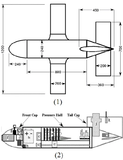
Figure 2-8 - (1)-Top view of ALBAC with the general dimensions. (2)- ALBAC schematic. a)CPU, b)Power Supply, c)Actuators, d)Gravity Sensor, e)Magnetic Sensor, f)Ranging Sensor, g)Velocity Sensor, h)Depth Sensor, i)Deballastor, j) Transponder, k)Thermistor, l)Tail Angle Trigger.[21] ... 14
Figure 2-9 - Airfoil Geometry. [29] ... 15
Figure 2-10 - Effect of aspect ratio on lift. [30] ... 18
Figure 2-11 - Effects of taper on lift distribution. [30] ... 19
Figure 2-12 - Cross sections of the four models used for drag tests and schematic of mechanism used to measure drag. The shapes are, from top to bottom, fat ellipsoid, the slender ellipsoid, the WRC prototype, and the UW/APL glider. Horizontal lines inside each figure show the volume-based lenght . [23] ... 21
Figure 2-13 - Measured drag coefficients, based on the useful-volume-based area , for the four half- scale models showed on Figure 2-12. Unlike all the scale models, the full-scale UW/APL model had wings that should make its drag higher than the hull-only models.[23] ... 21
Figure 4-1 - Symmetric airfoil concept to solve problem. ... 25
Figure 4-2 - Asymmetric airfoil concept to solve L/D problem. ... 26
Figure 4-3 -Possible concept to waterframe control - a) Top View b) Side View. ... 29
Figure 5-1 - Base Airfoil Drag Polars. Some of the used airfoils are not symmetric, but
we can modify them and make them symmetric. ... 41
Figure 5-2 - First iteration to obtain an optimized airfoil. In this step it was just changed the original airfoil and make it symmetric. ... 41
Figure 5-3 - Final optimized airfoil. ... 42
Figure 5-4 - Drag Polar for final airfoil. ... 42
Figure 5-5 - of final airfoil. ... 42
Figure 6-1 - Fuselage points in CATIA obtained from Excel. ... 47
Figure 6-2 - Fuselage shape. All measures are in millimeters. ... 48
Figure 6-3 - Tail boom geometry. All measures are in millimeters. ... 48
Figure 6-4 - Wing root airfoil coordinates. ... 50
Figure 6-5 - Wing points from Excel. ... 50
Figure 6-6 - Geometry of wing and its dimensions. All measures are in millimeters. ... 50
Figure 6-7 - Geometry of tail and its dimensions. All measures are in millimeters... 51
Figure 7-1 - PGW measurement of position of center of gravity... 53
Figure 7-2 - Wing and body axis [38] ... 55
Figure 7-3 - Moment sign convention. [38] ... 55
Figure 7-4 - Wing definition. [38] ... 56
Figure 7-5 - Wing geometry on XFLR5. ... 58
Figure 7-6 - Body definition on XFLR5. ... 58
Figure 7-7 - Aspect of glider on XFLR5. ... 60
Figure 7-8 - Convention of body and stability axes adopted by XFLR5. [38] ... 60
Figure 7-9 - Polars of vehicle's airfoil. ... 62
Figure 7-10 - Glider simulation on XFLR5. ... 63
Figure 8-1 - Aspect of machined wing plugs. ... 67
Figure 8-2 - Aspect of the plug after painting. ... 67
Figure 8-3 - Plug prepared to receive the plaster for mould construction. ... 68
Figure 8-4 - Final plaster moulds. ... 68
Figure 8-5 - Filling the wing's mould with resin. ... 68
Figure 8-6 - Released resin wing ... 69
Figure 8-7 - Intermediate aspect of the wing. Corrections on trailing edge were applied to make it smooth and constant. ... 69
Figure 8-8 - Tail's plaster moulds. ... 69
Figure 8-9 - Appearance of glued planks. On the image on the left is possible to watch all planks glued, and in the image on the right is showed the hole inside to accommodate extra ballast. ... 70
Figure 8-11 - Illustration of handwork during fuselage machining, and on the right, the intermediate shape of the fuselage. ... 71 Figure 8-12 - Comparison between ideal shape and handwork machined shape. The
small gaps present in this figure were eliminated later. ... 71 Figure 8-13 - Final machined shape of fuselage. ... 71 Figure 8-14 - Final machined tail boom ... 72
List of Charts
Chart 2-1 - Typical distribution. is plotted "upside-down" with negative values (suction), higher on the plot. This is done so that the upper surface of a conventional lifting airfoil corresponds to the upper curve. [29] ... 16 Chart 2-2 - Shape of pressure distributions on an airfoil. [29] ... 17 Chart 5-1 - Initial calculations to defining the size of vehicle. This graph was obtained
with an Aspect Ratio of 5 and red curve shows aspect ratio doubled to 10. ... 35 Chart 5-2 - variation due to increasing buoyancy volume. The values on axis
represent half buoyancy volume. ... 36 Chart 5-3 - Glide Ratio vs Speed. The values are obtained for a 3 different values of
buoyancy volume: ... 37 Chart 5-4 - Variation of Specific Energy due to speed variation. ... 38 Chart 5-5 - Glide Ratio for different values of speed. The values were obtained for a fix
buoyancy volume of . ... 38 Chart 5-6 - Influence of wing's aspect ratio on glide ratio, for 3 different values of
speed. ... 39 Chart 5-7 - Influence of on wing area. ... 39 Chart 5-8 - vs Glide Ratio. This chart allow us determining the for a specific glide
ratio. ... 40 Chart 5-9 - Drag polar of optimized airfoil. This chart only represents the lowest drag
area. ... 43 Chart 5-10 - Influence of tail arm length into tail area ... 46 Chart 6-1 - Comparison of elliptical wing chord distribution and tapered wing with the
chord distribution presented on Equations 6.2-1 and 6.2-2. ... 49 Chart 7-1 - Estimation of performance obtained from XFLR5. ... 65
List of Tables
Table 3-1 - Project Requirements ... 23 Table 5-1 - Customer Initial Requirements ... 34 Table 5-2 - Required volume for each subsystem. ... 35 Table 5-3 - Updated necessary space for each subsystem. ... 36 Table 5-4 - Main characteristics of design point. ... 40 Table 5-5 - Airfoil Characteristics. ... 43 Table 5-6 - PGW Energetic and Hydrodynamic Performance ... 45 Table 5-7 - Tail Sizing. ... 46 Table 6-1 - Characteristics of the wing ... 49 Table 7-1 - Main parameters of vehicle. ... 54 Table 7-2 - Center of buoyancy coordinates. The origin of axis system is the point
located on the nose of the fuselage of the vehicle as can be seen on the Figure 7-1. ... 54 Table 7-3 - Values of Moments of Inertia. ... 54 Table 7-4 - Wing panels definition. ... 57 Table 7-5 - Tail definition on XFLR5. The offset of the leading edge was calculated to
keep the distance between quarter chord of wing and quarter chord of tail fin equal to . This coordinates are valid to the horizontal tail (with 30º dihedral) and also for vertical fin. ... 59 Table 7-6 - Inputs of first type of analysis. ... 62 Table 7-7 - Input parameters for aerodynamic coefficients calculation. ... 63 Table 7-8 - Non Dimensional Longitudinal Coefficients ... 64 Table 7-9 - Non Dimensional Lateral Coefficients ... 64
Nomenclature
frontal area of vehicle aspect ratio
fin aspect ratio → fin span
wing span
center of buoyancy coordinate along xx center of buoyancy coordinate along yy center of buoyancy coordinate along zz
airfoil parasite drag coefficient
airfoil drag coefficient
waterframe parasite drag coefficient
waterframe total drag coefficient
pressure coefficient lower surface pressure coefficient upper surface
fin chord
horizontal tail volume coefficient lift coefficient
pressure coefficient
wing root chord wing tip chord
vertical tail volume coefficient
wing mean chord[m] total number of cycles
drag force
difference between initial and final depths
energy spent per dive specific energy
total energy necessary for maximum range
Oswald factor
center of gravity coordinate along xx center of gravity coordinate along yy center of gravity coordinate along zz gravitational acceleration
maximum depth (surface was considered h=0)
Initial depth
moment of inertia of PGW moment of inertia of PGW moment of inertia of PGW
moment of inertia of PGW
glide ratio
distance traveled per dive cycle
horizontal tail arm from center of gravity vertical tail arm from center of gravity distance traveled
lift force number of spheres
freestream static pressure roll rate static pressure dynamic pressure range yaw rate body radius
exponential Reynolds number for Mark Drela model
reference Reynolds number for Mark Drela model
volume Reynolds number Reynolds number
individual fin area
horizontal tail area
tail area
vertical tail area wing area
time per dive cycle
total time for maximum range
airfoil thickness
variation of speed along the x-axis freestream velocity
body volume
buoyancy volume
variation of speed along the y-axis
horizontal velocity maximum velocity minimum velocity
half of buoyancy volume velocity of vehicle maximum propulsive force variation of speed along the z-axis
position of station
position of center of gravity in x-axis
maximum thickness point
→ position of center of gravity in y-axis → position of center of gravity in Z-axis
→ trajectory angle [°] λ →taper ratio
dynamic viscosity of seawater kinematic seawater viscosity density of seawater
1 - Introduction
1.1 Motivation
Some three-quarters of the Earth's surface is covered by water and only about 0.1% of oceans bottoms have been explored.[1]
Historically, the ocean bottoms has been mainly observed using instruments lowered from research ships or, later, suspended from moorings. The relatively high cost of these observation platforms has limited their number and, consequently, the spatial and temporal density at witch oceans has been observed.[2]
To solve this problem began to be developed the Autonomous Underwater Vehicles (AUVs) and in particular the Autonomous Underwater Gliders.
With this vehicles it is now possible for the scientists make more complex studies on topics such as the effect of metals, pesticides and nutrients on fish abundance, reproductive success and ability to feed or on contaminants such as chemicals such as chemicals or biological toxins that are transported in particulate form and become incorporated into living organisms (plankton, bivalves, fishes) or become deposited in bottom sediments.[3,4]
This vehicle, however, has a different specific purpose: locating potential areas in the ocean that would be suitable for sea farming. These farms would provide sources of protein to nations that are in need of food. The PGW will be equipped with an optical sensor that counts the number of blue-green algae in a given area of the ocean. Blue-green algae are at the bottom of the oceanic food chain and counting them allows researchers to estimate and track the fish population in given locations, and make predictions for changes in populations over time. The data collected from the PGW will help researchers monitor the fish population and effectively implement sea farming.[5]
1.2 Objective
The objective of this work is developing the waterframe for a low cost, effective, efficient sea glider, autonomous underwater vehicle (AUV) that can be produced in mass quantities.
1.3 Overview
Chapter 1 provides the motivation for the development of this vehicles and the objective of this thesis.
Chapter 2 presents a brief historic development of underwater vehicles and their applications. In addition presents a competing product review and some scientific research like airfoil design, wing design and possible fuselage shapes.
Chapter 3 shows a table with customer requirements, which should be guaranteed in all design process.
Chapter 4 provides some specific concepts as initial study to begin the design of a new vehicle.
Chapter 5 demonstrates how was calculated the design point and the performance specifications of the vehicle.
Chapter 6 shows the final geometry and dimensions of the different subparts of the vehicle.
Chapter 7 provides the stability coefficients calculation for the designed vehicle. Chapter 8 shows the construction of different parts of half scale prototype.
2 - Bibliographic Review
2.1 Underwater Vehicles
2.1.1 History
To understand the development process of underwater vehicles we shall first explore previous research conducted in development of this type of vehicles.
Underwater vehicles were invented to address scientists frequent need to monitor underwater areas over long periods of time. This job, like we saw before, was very expensive when were used ships or even manned submersibles. [6]
The first research in this area resulted from the need to study arctic under ice profiles in the late 1950s. Murphy et al (1957) was developed "Special Purpose Underwater
Research Vehicle" (SPURV) in the Applied Physics Laboratory at the University of Washington.
This underwater vehicle was machined by Boeing from a forging 7078-T6 aluminum alloy. [4] The SPURV was operated at for close to hours. The vehicle had a maximum depth of , could communicate acoustically with the surface and was autonomously at constant pressure, between two depths, or a constant climb or dive angle.
The French Research Institute for Exploitation of the Sea, IFREMER, designed and developed Epulard in 1976, and deployed it for the first dive in 1980. This vehicle also was acoustically controlled and had a maximum depth of . Epulard successfully completed about dives between 1980 and 1990.
The vehicle was capable to maintain a constant altitude above the ocean bottom by dragging a cable.[7]
In the end of 1970s at Naval Ocean Systems Center was developed the "Advanced
Unmanned Search System" (AUSS). This vehicle was launched a first time in 1983 and
completed over 114 dives up to a depth of . [8]
The AUSS was long, in diameter had silver zinc batteries and it had an acoustic communication system that transmitted video images through the water. The vehicle was compact and portable, easily fitting on an offshore supply boat. The center section of vehicle was a cylindrical graphite epoxy pressure hull with titanium hemispherical ends. The free flooded forward and aft end fairings and structure were made of Spectra, a nearly buoyant composite.[9]
Busby's et al. wrote Undersea Vehicle Directory, where they mentioned that there
were six operational AUVs and an additional 15 others under construction.
In the early of the interest in UAVs began to significantly pick up and many others vehicles were developed.
The Massachusetts Institute of Technology’s Sea Grant AUV lab developed six Odyssey vehicles during the early 90’s. These vehicles displaced , could operate at for up to six hours, and were rated to . Odyssey vehicles were operated under ice in
1994, and to a depth of for hours in the open ocean in 1995. [10] Odyssey vehicles were also used in support of experiments demonstrating the Autonomous Ocean Sampling Network during this period [11]. The schematic of odyssey is represented on Figure 2-1.
Figure 2-1 - Schematic of Odyssey. The outer faired surface is a low drag form. A ducted propeller
minimizes fouling. Steering is by cruciform control surfaces.
In the early 90's the Woods Hole Oceanographic Institute (WHOI) created the "Autonomous Benthic Explorer" (ABE). The ABE was the first vehicle completely independent of the surface vessel and capable of covering large areas of underwater terrain.
ABE had a gross weight of and made approximately dives to the deep seafloor. Typical dives lasted about hours depending on the instrument payload and the bottom terrain. Later, were made some modifications that included a multibeam sonar (SM2000), which was used on a recent survey of the Explorer Ridge. [12]
At the same time, in South Hampton Oceanography Center was developed the first vehicle prepared for long duration mission. The AUTOSUB is a long range, deep diving, autonomous underwater vehicle. It displaces can travelling at and has days operation time. It has completed missions and travelled about . Long mission lasted hours and Stub travelled . [13]
In the late 90’s WHOI introduced REMUS, an AUV displacing , to support scientific objectives. It could operate for 20 hours at a speed of at up to depth. Hundreds of people have been successfully trained in the use of REMUS vehicles. It is not possible to determine how many missions have been performed by REMUS. [8]
The second half of the 1990’s saw increasing funding and support of the glider concept from the Office of Naval Research, in part as an element of the AOSN initiative. This led to three programs to design and develop oceanographic gliders: the Slocum glider at WRC, Seaglider at University of Washington, and Spray at SIO. Within the last ten years, these groups have developed these underwater gliders and deployed them in large-scale
oceanography projects. These three glider designs are now approaching the end of their development phase [14]. Gliders also show great potential in other applications. Recent studies show exciting possibilities for glider performance and future designs. [15]
The year 2002 saw the first commercial sales of gliders. These electric Slocum gliders sold by WRC to WHOI are the first to be operated by a group that had not built the glider themselves. Early operations by the WHOI Glider Lab took place in Buzzards Bay, off Cape Cod, Massachusetts. In January 2003 that laboratory, directed by David Fratantoni, deployed three Slocum Electric gliders in operations from a vessel in the Bahamas. Tests of a thermally driven Slocum glider were conducted by WRC concurrently. [3]
In Japan, the long, ALBAC was designed as a one-profile glider with a maximum depth of m. It used wings to control its motion through the water on descent, and on reaching its destination depth, dropped a weight to return, gliding upwards to the surface. [16]
2.1.2 Underwater Gliders - A particular type of underwater
vehicles
Henry Stommel envisioned a world ocean observing system based on "a fleet of small neutrally-buoyant floats called Slocums" that "migrate vertically through the ocean by changing ballast, and they can be steered horizontally by gliding on wings at about a 35 degrees angle . . . During brief moments at the surface, they transmit their accumulated data and receive instructions . . . Their speed is generally about ." [2]
An underwater glider is a type of buoyancy propelled, fixed wing underwater vehicle without external active propulsion.[17] They alternately reduce and expand displaced volume to dive and climb through the ocean. Unlike floats, gliders additionally carry wings and control their pitch attitude to effectuate a horizontal speed component through the ocean.[14]
Buoyancy control, coupled with hydrodynamic lift is a natural choice for a platform designed to both profile and traverse the stratified ocean where gradients are near vertical and the tilt of surfaces is of key importance. Sensible sampling dictates glide slopes steep compared to isopleths, hence ocean gliders need not attain the shallow slopes of sail planes in the atmosphere.[14]
Gliders must have both long range and high endurance to be an effective alternative to ships. Glider economy stems from long range small size, remote control, and modestly priced data communication. Their small size allows them to be launched from a small boat and recovered few months later for reuse.
Range and endurance are highly dependent on mission objectives and the operating environment. Typically, in battery powered gliders, of available energy is intended to power and only is devoted to control, sensors and other systems.[2]
The high pressure pumps used to change buoyancy are usually inefficient at low pressure, so that deeper dives result in much longer range. Deeper dives also tend to encounter less current on average, which means an increased range over the ground.
The ratio between horizontal speed and vertical speed (glide slope) equals lift over drag and is typically to , much less than for an aeronautical glider but comparable with NASA Space Shuttle.[18]
Nowadays, underwater gliders are entirely autonomous, despite their operation can be controlled with two-way satellite communications.[16] When it is given a set of mission parameters, gliders follow them until they are changed or mission ends.
2.1.3 Applications
The first application of underwater gliders, and the inspiration for their development, has been oceanographic data collection. The importance of understanding the oceans and their role in the planet’s ecosystem cannot be overstated. Progress in oceanography depends in part on the gathering of scientific data from the oceans. Because of the distributed nature of ocean dynamics, data is needed over a wide temporal and spatial range. Progress in oceanography depends in part on the gathering of scientific data from the oceans. Because of the distributed nature of ocean dynamics, data is needed over a wide temporal and spatial range.
Gliders can be used in remote sensing for physical, chemical and biological oceanography by a low operating cost. [3]
The underwater gliders are inexpensive, offer a superior scientific sampling (depending of the installed sensors, they can do a large variety of measures over a long period of time). They may also be operated in coordinated groups and easily launched and recovered from an ocean going ship or even from a dock that has access to the world's oceans.
Some alternative methods to the underwater gliders are the use of ships, the use of fixed moorings or even the use of drifters, but ships are expensive to operate and are limited in number and availability. Fixed moorings just give data around a fixed location, while drifters cannot choose their path through the ocean.
The characteristic saw tooth motion gliders make is also well suited to oceanographic sampling. Variations of ocean water properties are generally much stronger in the vertical than horizontal directions, making vertical sampling important in oceanographic applications. For this reason, propeller driven AUVs and towed arrays are often flown in a vertical saw tooth pattern for data collection.
A typical mission of an underwater glider includes repeatedly surveying an area of the ocean over a long period or maintaining their position against ocean currents.
Oceanographic sampling also calls for the deployment of groups of gliders. In summer 2003, as part of the Autonomous Oceanographic Sampling Network II (AOSN II) experiment,
seventeen gliders were deployed in the Monterey Bay, California, over a six-week period. [19] As part of the experiment, the network of gliders performed adaptive sampling missions for specific purposes including updating and evaluating forecast models. This application made use of the gliders as a re-configurable sensor array and took advantage of the available data from the sampling network to plan glider trajectories. [19]
Some examples of other underwater gliders applications can be easily achieved. Military applications such as tactical oceanography and maritime reconnaissance that is some quiet different from oceanographic science for which they were invented. Military applications include use the vehicles as communications gateways or navigation aids. Gliders can also be operate in both deep ocean and coastal environments. [20]
Because they do not have thrusters and use internal actuators, gliders are very quiet. This is very useful for military applications, because quieter vehicles are more difficult to be detected by the enemy.
2.2 Competing Products Review
In this section will be described the designs of existing gliders which some of them are similar to PGW project objectives. This is intend to show the present state of the art in underwater gliders and to guide the development of this glider design.
Three buoyancy driven autonomous underwater gliders, Slocum, Spray and Seaglider have been developed and deployed in the United States of America.
Spray was developed from Scripps Institution of Oceanography (SIO), Seaglider from University of Washington and Slocum from Woods Hole Oceanographic Institution.
In Japan, at the University of Tokyo have been developed an underwater glider called ALBAC. This vehicle is driven by a drop weight instead of a ballast system. [21]
At "École Nationale Supérieur D'Inginiéurs", in France was developed a vehicle whose name is STERNE. STERNE is a hybrid vehicle with both ballast control and a thruster. [22]
2.2.1 Spray
The Spray underwater glider was developed at Scripps Institution of Oceanography, is meant to fill the need for a relatively long-lived vehicle to observe ocean physics and biology. In trying to define the general circulation, or climate variability like the El Niño-Southern Oscillation (ENSO), mesoscale variability is the main source of competing noise. For biological communities the mesoscale represents an often-dominant perturbation to be observed. The main confusing noises in describing the mesoscale are quasi-diurnal phenomena like the diurnal cycle, internal tides, inertial waves, and weather events. To describe the typical seasonal state, or to define typical relations occurring on the mesoscale, it is necessary to observe many mesoscale realizations, which translates to years of operation.
The design missions for spray glider are a combination of three archetypes: time series, transects, and roving assistants to research cruises.
The Spray oceanographic glider is two meters long and has a mass of . Spray has a range about to at . It uses lithium batteries, which have better energy density and performance than alkaline batteries. [23] Spray has a cylindrical pressure hull with two wings and a vertical tail. The hull employs a finer entry shape than the Webb Research Corporation glider hull, which has about higher drag. [23] A flooded fairing forms the rear of the hull and houses the external oil-filled bladder for the ballast system.[3]
This underwater glider is optimized for long-duration, long-range, deep ocean use where the emphasis is on energy efficiency. Spray oceanic glider employs a high-pressure wobble-plate reciprocating pump and external bladders in the same hydraulic configuration as ALACE floats. [24] GPS and satellite communication antennas are housed in a wing that is rolled vertical during communication like is shown in Figure 2-2.
Figure 2-2 - Spray's method of travel (Spray 2008b) [4]
The vertical stabilizer houses an emergency-recovery antenna. Scientific sensors may be mounted on the hull or aft of the pressure hull in the flooded compartment which supports the vertical stabilizer.
Glide control in Spray is achieved using two internal moving masses: one for pitch and other for roll. The pitch battery pack has a range of travel of and moving vehicle's center of gravity.[3] The roll actuator is also a battery pack, but located in the nose of the vehicle and can rotate degrees, as we can see in Figure 2-3.
Figure 2-3 - Spray Schematics (Spray 2008b) Forward of the wings is a top of view, aft is a view from
the port side. The hull is formed by three pieces. Separate battery packs are moved to control pitch and roll. Antennas are enclosed in a wing that is rolled vertical on the surface. An aft flooded section houses hydraulic bladders and some science sensors. [4]
To maneuver, Spray is initially starts by rolling. This gives a horizontal component to the lift vector and induces vehicle starting sideslip in the plane of the wing in the direction of the buoyant force. The horizontal component of lift provides the centripetal force for turning while sideslip acting on the vertical stabilizer produces the yaw moment needed to change vehicle heading. For example, to turn right during descent phase, the right wing is dropped, like a conventional airplane, which generating a lift component to the right that drives the vehicle to the right. Sideslips down and to the right acts on the vertical stabilizer causing the nose to yaw to the right. To turn right in ascent the glider is rolled oppositely by dropping the left wing.
2.2.2 Slocum Battery
The Slocum Battery was developed from Webb Research Corporation and it is comprised of three main separate hull sections in addition to two wet sections located fore and aft. The cylindrical hull sections are made in aluminum alloy chosen due to its simplicity, economy, and expandability. The nose end cap is a machined pressure resistant elliptical shape, and the tail cap a truncated cone to allow for penetrator surface.
Slocum has fixed wings, with one meter span. The wing sections are flat plate and they are made in composites and are easily replaced. [25] The wings are swept 45 degrees because in all operations, particularly coastal work, there is a risk of entraining weed on the wings causing major degradation in gliding performance. [25]
The tail has long and houses the antenna for GPS and communications. Horizontal tail surfaces are not required since pitch stability is provided by the wings, which are mounted aft of the center of buoyancy.[26]
This glider is electrically powered, its operational envelope includes a depth capability and a projected endurance, which translates into approximately operational range with a fixed horizontal speed and vertical speed.
The Slocum Glider has long, in diameter and his mass is approximately . It maneuvers through the ocean in sawthooth-shaped gliding trajectory. It is controlled by two different methods. The pitch and roll are controlled by translating and rotating the internal battery packs. [4] A rudder controls the turning rate and the pitch and the buoyancy ate the surface are aided by the inflation of a bladder.
The glider has two onboard computers, a control computer and a science computer. Navigation sensors on the glider measure heading, pitch, roll, depth, sliding mass position and the piston drive position. These readings are recorded and processed by the control computer. Vehicle position at the surface is determined by a GPS receiver. Note that while submerged the glider velocity and horizontal position are not sensed because of the difficulty in measuring these states. [3]
The Slocum glider can be programmed to navigate in various ways. For a typical mission scenario the glider navigates to a set of preprogrammed waypoints specified by the operator. A mission file with these waypoints, desired glide path angles, speed, and other parameters, may be transmitted to the glider before the start of the mission. The glider is then capable of operating autonomously and navigating with dead reckoning and closed-loop pitch and heading control.
2.2.3 Slocum Thermal
The Slocum Thermal glider was developed and optimized for long duration missions. The Slocum thermal glider harvesting the energy needed for its propulsion from the ocean's temperature gradient.
In missions with electric-powered gliders, 60-85% of the energy is consumed into propulsion. [2,4] A thermal-powered glider may have a range times that of a similar electric powered vehicle. [4]
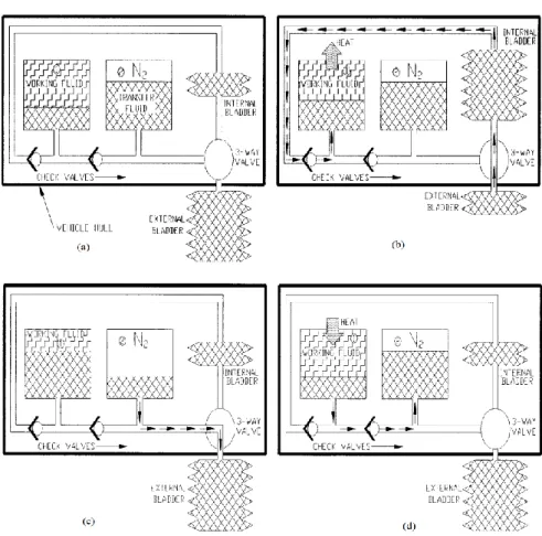
Slocum Thermal propulsion depends on the volume change associated with melting a material with a freezing point in the range of ocean temperatures. In warm surface waters the working fluid is heated, melts and expands. This expansion compresses an accumulator where energy is stored. Descent is initiated by transferring fluid from an external bladder to an internal reservoir. At temperatures colder than freezing point of fluid used, the freezing contraction draws fluid out of the internal reservoir into the heat exchanger. For ascent, energy stored in the accumulator does the pressure-volume work and the cycle repeats. This method of propulsion can be better understood on Figure 2-5. The heat exchange volume is inside tubes that run the vehicle's length (see Figure 2-6) and provide a large surface area for rapid heat flow.
Figure 2-5 - Slocum's thermodynamic cycle. (a) Equilibrium conditions at surface before descent. (b)
Descent with heat flow to water. (c) Beginning of ascent. (d) Ascent, heat flowing from water, returned to equilibrium as in (a). [26]
Slocum Thermal is controlled by changing the position of the center of gravity with respect to the center of buoyancy, thus controlling both pitch and roll. As in Slocum Battery, roll results in a yaw moment thus steering the glider. The main battery is eccentrically mounted and supported on a carriage equipped with pitch and roll actuators. Most of the pitch moment is generated by the movement of fluid in the main buoyancy changer, and the moment due to controlled movement of the battery is used for fine adjustment of pitch angle. [26]
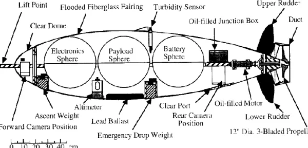
The outer shape of the Slocum Thermal is very similar to Slocum Battery, which was previously described. Maximum depth of Slocum Thermal is and his horizontal speed is close to at dive angle. The vehicle weights approximately in air, and has a maximum diameter of .
Figure 2-6 - Outer shape of Slocum Thermal Glider. [26]
2.2.4 Seaglider
Seaglider was developed at University of Washington Applied Physics Lab, and its purpose is doing extended oceanographic sampling missions. Seaglider is enclosed in a hydrodynamic fiberglass fairing supporting wings, a vertical stabilizer and trailing antenna staff. His hull is made up of an internal pressure hull and an external fairing. The fairing is long with maximum diameter and is free flooding. The fairing is a low-drag hydrodynamic shape and retains a laminar boundary layer forward of this maximum-diameter point. Due to different design philosophy used than other gliders, its shape is derived from a low drag laminar flow shape used by the U.S. Navy in target drones. The shape was designed to reduce pressure drag by developing a favorable pressure gradient at the rear of the vehicle. It is possible to see the fairing shape in Figure 2-7. [3]
It has a range of and has a mass of in air. A curious aspect is that Seaglider has an internal isopycnal hull, which is a hull with same compressibility as seawater. This special hull reduces the ballast pumping requirements: "this feature extends vehicle range by as much as fifty percent over a conventional stiff hull" [27].
The Seaglider has a fixed wing with one meter span and vertical tail fins located above and below the body. The vehicle efficiently maintains position in weak currents by pitching to near vertical and using minimal buoyancy forcing.
Buoyancy control is provided by ALACE's hydraulic system. Movement of internal masses controls gliding and pitches the vehicle forward to raise the trailing antenna mast during communication and navigation. The wing is so far aft that the turning dynamics are opposite that of Spray. In descent phase, to turn right, the vehicle's left wing is dropped so that lift on the wing drives the stern to left, overcoming lift off the vertical stabilizer, and initiating a turn to the right. Hydrodynamic lift on the side slipping hull produces the centripetal force to curve the course. However, in ascent phase a roll to the left side produces a left turn. [2]
Figure 2-7 - Schematic design of Seaglider. The Bottom shows a side view with the wing shape provided
above for reference. The antenna mast is shown separately above the fairing and pressure hull. Four cross sectional views at an expanded scale are shown at the top of the figure.[27]
2.2.5 ALBAC
The ALBAC was designed and constructed in 1992 in Sugura Bay, Japan. The glider was developed at the University of Tokyo in the laboratory of Tamaki Ura for oceanographic measurement of water column and from sea bottom observation. [21] This design is notable because it is a shuttle type glider designed to conduct dives from a ship and does not have a
buoyancy control system. ALBAC is driven by a drop weight which it carries on one downward glide and then releases to ascend back to the surface, conducting a single trip to depth between deployment and retrieval.
To control the attitude and trajectory, an actuator system displaces the location of the center of gravity longitudinally and laterally by moving a weight like Seaglider. Because it has no ballast pump, ALBAC carries batteries to power only its instruments and actuators.
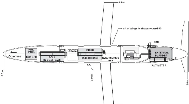
The ALBAC has fixed wings and a vertical and horizontal tail. Since it has wings ALBAC can move horizontally without consuming energy of batteries by gliding up to 20 degrees down from the horizontal plane. It is long, weighs , and can dive to depths of at speeds of . It has horizontal tail fins which change angle at inflection from downwards to upwards gliding, a feature not present in other gliders. The wings and tail are larger in comparison to the body than on Slocum, Spray or Seaglider.
ALBAC carries flight sensors including compass, depth, pitch, roll, and a propeller-type water speed indicator.
Figure 2-8 - (1)-Top view of ALBAC with the general dimensions. (2)- ALBAC schematic. a)CPU, b)Power
Supply, c)Actuators, d)Gravity Sensor, e)Magnetic Sensor, f)Ranging Sensor, g)Velocity Sensor, h)Depth Sensor, i)Deballastor, j) Transponder, k)Thermistor, l)Tail Angle Trigger.[21]
2.3 Airfoil Design
The airfoil shape variation has deterministic effect on the aerodynamic coefficients. The ideal shape of an airfoil depends mainly on the angle of attack, Reynolds number, Mach number, surface roughness and fluid turbulence. [28]
Some airfoils are designed to produce low drag (and may not be required to generate lift at all) while other airfoils may need to produce low drag while producing a given amount of lift. In some cases, the drag does not really matter - it is maximum lift that is important.
In this section will be presented the influence of different parameters in airfoil performance as well as some different airfoil design methods.
2.3.1 Airfoil Geometry
The geometry of an airfoil can be characterized by its both upper and lower surfaces coordinates, but there are a few more parameters that can be used to describe and characterize an airfoil such as: nose radius, maximum camber, and maximum thickness, position of maximum camber and position of maximum thickness. In Figure 2-9 it is possible observe all of these parameters which allow the characterization of airfoils.
Figure 2-9 - Airfoil Geometry. [29]
2.3.2 Airfoil pressure distributions and performance
The performance of airfoils can be easily studied by reference to the distribution of pressure over the airfoil. This distribution is usually given by:
2.3-1
Pressure coefficient is the difference between local static pressure and freestream static pressure, nondimensionalized by the freestream dynamic pressure. [29]
This coefficient is ever lower than 1 and depends on the geometry of the airfoil that being analyzed. On Chart 2-1 is presented a plot of . varies from 0 (at leading edge) to 1 (at trailing edge).
Chart 2-1 - Typical distribution. is plotted "upside-down" with negative values (suction), higher on the plot. This is done so that the upper surface of a conventional lifting airfoil corresponds to the upper
curve. [29]
At upper surface pressure is lower (usually is plotted higher) than on the lower surface, but it does not have to be. Sometimes, the lower surface carries a positive pressure (usually plotted lower) but in Chart 2-1 is possible observe some suction present near the midchord.
The region of pressure distribution is called the pressure recovery region. In this region pressure increases from its minimum value to the value at the trailing edge. This region is also known as the area of adverse pressure gradient and this adverse pressure gradient is associated with boundary layer transition and possible separation if the gradient is to severe.
For a symmetric airfoil and angle of attack, , is maximum at leading edge and its value is about 1. For infinitely thin sections at the trailing edge.
With distributions we can achieve , which are given by:
2.3-2
The performance of an airfoil is directly related to the shape of pressure distribution as indicated on the Chart 2-2.
Chart 2-2 - Shape of pressure distributions on an airfoil. [29]
2.3.3 Airfoil Design philosophies
In the past, airfoils were designed experimentally. A designer engineer would build a model based on experience, place it in a wind tunnel, record the results, and make some adjustments to the airfoil model if it did not perform satisfactorily. Often, these airfoils were classified into several families that could be placed into a catalogue of airfoils. The engineer would then choose the appropriate airfoil or airfoils for a vehicle based on the recorded experimental data.
Nowadays, with computers this process has changed significantly. An engineer can make custom airfoils at almost any design condition, can simulate the wing planform to calculate its performance.
There are two main approaches used for custom airfoil design: direct design or inverse design. [30]
The direct airfoil design methods involve the specification of section geometry and the calculation of pressure and performance. The simplest form of direct airfoil design consists of starting with an assumed airfoil (such as NACA airfoil), determining the characteristic of the section and fixing the existing problems. This process is repeated until there is no major problem with the section. [29]
Inverse design, in other hand, uses the target pressure distribution as an objective function. The basic idea behind a variety of methods of inverse design is to specify the desired distribution and use the least squares difference between the actual and target 's as the objective. [29]
2.4 Wing Geometry
There are many issues that can affect the performance of wings. In this section will be presented some of that aspects and will be explained how each one changes the performance of the wings.
2.4.1 Aspect Ratio
Aspect Ratio is defined as the span squared divided by the area as shown in Eq. 2.4-1.
2.4-1
This affects directly the slope of the lifting curve
. The larger the aspect ratio the
more nearly does the lift slope approaches the theoretical maximum for an infinitely long wing. [32] This happens because a wing with a high aspect ratio has tips farther apart than an equal area wing with low aspect ratio. Therefore, the amount of the wing affected by the tip vortex is less for a high aspect ratio wing than for a low aspect ratio wing and the strength of the tip vortex is reduced.
Figure 2-10 - Effect of aspect ratio on lift. [30]
2.4.2 Wing Sweep
Wing sweep is usually used to reduce the adverse effects of transonic and supersonic flow. But PGW project, neither transonic nor supersonic flows are a problem due to the extra low speeds of the vehicle.
Other consideration about wing sweep is that wing sweep improves stability. A swept wing has a natural dihedral effect. In many cases is necessary to use negative dihedral to avoid excessive stability. [30]
2.4.3 Wing Taper Ratio
This is the ratio between the tip chord and the centerline root chord.
2.4-2
Taper affects the lift distribution along the wing's span. As proven by the Prandtl [31] wing theory, minimum drag due to lift occurs when the lift is distributed in an elliptical fashion.
Figure 2-11 - Effects of taper on lift distribution. [30]
An elliptical wing planform is difficult and expensive to build. The easiest wing planform to build is an untapered rectangular wing . However, the untapered wing has a constant chord along the span and so has excessive chord towards the tip. [32] When compared with an elliptical wing, an untwisted rectangular wing has about more drag due to lift. [30]
2.4.4 Wing Incidence
Wing incidence angle is the pitch angle of the wing with respect to the fuselage. Usually, this angle is chosen to minimize drag at some operating conditions.
The incidence angle is chosen such that when the wing is at correct angle of attack for the selected design condition, the fuselage is at angle of attack for minimum drag. [32]
If we have a variable wing incidence angle, we can use angle's change as a way to provide vehicle control.
2.5 Low Drag Shapes
To maximize the performance of the vehicle is absolutely essential that its drag is as lower as possible. There are many issues that can affect the performance of the vehicle and the fuselage shape is one of the most important subjects. In this section some methods to design low drag shapes are analyzed.
2.5.1 Axisymmetric Bodies
One of the possible ways to reduce drag is increasing the laminarization of the boundary layer, which plays an important role in aerodynamic aircraft design [33] and also in hydrodynamic of underwater vehicles.
For the aerodynamic design of three-dimensional fuselages with low skin-friction drag, laminar bodies of revolution are often used as a basis. [33]
One of the major problems on underwater bodies design is laminar to turbulent transition. This is a complex and yet not fully understood phenomenon.
A correct theoretical model calculation of the controlled transition process is only possible with direct numerical simulations by solving the complete unsteady Navier Stokes equations. [33]
J. S. Parsons and R.E. Goodson developed a shape for axisymmetric bodies for minimum drag for an incompressible flow.[35]
The fact that extensive laminar flow can exist in the ocean environment at these high Reynolds numbers is in itself significant.[35] The geometry that they developed provides a laminar flow until 70% of total length, which produces lower drag than turbulent flow.
Eriksen [14] describes the University of Washington Applied Physics Laboratory (UW/APL) laminar-flow shape that involves a free-flooding hydrodynamic shroud around the pressure case.
In 1995, Webb [36] carried out pool tests of a glider hull designed by WRC. These tests were intended to confirm performance calculations such as those above, but the results were not consistent enough to define the hull drag to better than about 50%.
Some studies to compare the different shapes drag were performed. On Figure 2-12 it is possible to observe 4 cross sections of low drag shapes and on Figure 2-13 is presented the drag measured for each shape.
Figure 2-12 - Cross sections of the four models used for drag tests and schematic of mechanism used to
measure drag. The shapes are, from top to bottom, fat ellipsoid, the slender ellipsoid, the WRC prototype, and the UW/APL glider. Horizontal lines inside each figure show the volume-based length
. [23]
The study concluded that all the shapes have approximately constant drag coefficients except the laminar-flow form. The slender ellipsoid has the smallest of the constant drag coefficients, with (based on frontal cross section is ). The WRC shape is higher by and the fat ellipsoid higher by . The drag coefficient for the UW/APL shape decreases as and has approximately the same drag as the slender ellipsoid at, which for full size vehicles corresponds to a speed near . [23]
Figure 2-13 -Measured drag coefficients, based on the useful-volume-based area, for the four half- scale models showed on Figure 2-12. Unlike all the scale models, the full-scale UW/APL model had wings that should make its drag higher than the hull-only models.[23]
This page has been intentionally left blank for double side copying
3 - Customer Requirements
Since the objective of this thesis is develop a new vehicle with collaboration of University of Saint Thomas and Scott Morgan it is necessary to define the requirements to start the design process.
The initial requirements of the project can be observed on Table 3-1. Table 3-1 - Project Requirements
*1 The PGW shall be capable of autonomous operation for a minimum period of 4 contiguous months before periodic maintenance is required to be performed. 2 The PGW shall be capable of surviving in an ocean environment.
*3 The PGW shall be able to transmit a distress code if caught and unable to surface by normal propulsion. 4 The PGW shall be launched and recovered from an ocean going ship or from a dock that has access to the world’s oceans. *5 The PGW shall be designed for a deployed useful life of 2 years for the navigation systems. 6 The PGW shall be designed for a deployed useful life of 5 years for the waterframe before refitting. *7 The PGW shall be designed for a deployed useful life of 2 years for the power subsystem. *8 The PGW shall be able to navigate to a minimum accuracy of 1000 meters left or right of the desired programmed course upon returning to the surface after
a dive of 300 meters. *9
The PGW shall, upon surfacing, determine its position latitude and longitude, speed progressing forward and determine a new trajectory for the next bounce.
*10
In the event that negative progress be possible by the PGW, a message shall be passed to the command and control element requesting a new heading allowing forward progress in the given conditions.
**11 The PGW shall be capable of bidirectional Line of Sight communications up to 20 kilometers from 2 Pi radians while station keeping at the surface.
**12 The PGW communications shall be secured by the use of hopping waveform communications, and secure command and control protocols. **13 The PGW shall have a sailfin that provides for an isotropic antenna for communications. **14
The PGW antenna shall be a color that is highly visible and easily recognized as a manmade object to be steered away from by all ships within ¼ nautical mile.
*15 The PGW shall be capable of powering all of the systems for at least 4 months. *16 Any expendable fluid used in the propulsion system shall be bio-degradable.
* Part of UST's design
This page has been intentionally left blank for double side copying
4 - Problem Definition and Concepts
Identification
In this chapter will be identified the applicable concepts to solve specific problems. A requirements review is necessary to fix the problems and identify possible solutions to solve it.
4.1 Dive and Climbing -
problem
As said above, the vehicle should be capable to traveling the largest distance possible in one dive cycle. At the same time, the vehicle needs to return the surface when it finds itself at the point of maximum depth. To solve this problem we identified 3 possible concepts.
4.1.1 Symmetric Airfoil
This concept consists in a simple symmetric airfoil like "NACA-00" series or even a flat plate, which can generate lift with the same in both descending and ascending phases. With this type of airfoil the wings are symmetrical and able to glide in both upward and downward phases with same lift, producing a symmetrical trajectory.
The main disadvantage of these type of airfoils is the lower compared with cambered airfoils. In Figure 4-1 we can see an illustration of this type of airfoils and resultant lift force direction in both descent and ascent phases.
![Figura 1 - Esquema de operação de um planador subaquático. [5]](https://thumb-eu.123doks.com/thumbv2/123dok_br/18877429.932063/11.892.207.730.557.819/figura-esquema-de-operação-de-um-planador-subaquático.webp)
![Figure 2-2 - Spray's method of travel (Spray 2008b) [4]](https://thumb-eu.123doks.com/thumbv2/123dok_br/18877429.932063/36.893.224.630.487.768/figure-spray-s-method-travel-spray-b.webp)
![Figure 2-4 - Slocum Schematics. [25]](https://thumb-eu.123doks.com/thumbv2/123dok_br/18877429.932063/38.893.113.739.709.1037/figure-slocum-schematics.webp)
![Figure 2-6 - Outer shape of Slocum Thermal Glider. [26]](https://thumb-eu.123doks.com/thumbv2/123dok_br/18877429.932063/40.893.195.655.395.725/figure-outer-shape-slocum-thermal-glider.webp)
![Figure 2-11 - Effects of taper on lift distribution. [30]](https://thumb-eu.123doks.com/thumbv2/123dok_br/18877429.932063/47.893.157.705.306.723/figure-effects-taper-lift-distribution.webp)