ISSN 0104-6632 Printed in Brazil
www.abeq.org.br/bjche
Vol. 33, No. 02, pp. 391 - 399, April - June, 2016 dx.doi.org/10.1590/0104-6632.20160332s20140209
Brazilian Journal
of Chemical
Engineering
THE COMPLETE MODELLING OF THE FILLING
PROCESS OF HYDROGEN ONBOARD VEHICLE
CYLINDERS
M. Deymi-Dashtebayaz
1*, M. Farzaneh-Gord
2, N. Nooralipoor
2and H. Niazmand
31
Hakim Sabzevari University, Faculty Member of Mechanical Engineering, Sabzevar, Iran. Phone: 0098 5144012814; Fax: 0098 5144012773
E-mail: [email protected]
2
The Faculty of Mechanical Engineering, Shahrood University of Technology, Shahrood, Iran. E-mail: [email protected]; [email protected]
3
Mechanical Engineering Department, Ferdowsi University of Mashhad, Mashhad, Iran. E-mail: [email protected]
(Submitted: December 21, 2014 ; Revised: March 28, 2015 ; Accepted: May 8, 2015)
Abstract - Complete modelling of the filling process occurring in a hydrogen-fueled vehicle storage cylinder is examined. A simultaneous modelling of the flow and heat transfer within the cylinder and cylinder wall has not been considered in previous studies. Rapid filling may result to an unexpected temperature rise and breaching of the safety standards. In the present study, initially a correlation was developed based on a numerical simulation for predicting the heat transfer rate between in-cylinder flow and the cylinder inside wall. Then, a thermodynamic model was developed for predicting transient variations of temperature and pressure inside the cylinder and wall temperature during the filling. The model was applied to a type III onboard storage cylinder filling process. The numerical results are compared with previously measured values and showed good agreement. The results also show that a great portion of heat dissipation from the in-cylinder flow is stored in the in-cylinder wall. It is also found that ambient temperature during the refueling process has considerable effects on filling behavior in general and in particular on the final in-cylinder temperature and filled mass.
Keywords: Hydrogen fuelling station; Fast-filling process; Heat transfer rate; Complete thermodynamic modelling.
INTRODUCTION
Utilization of hydrogen as a clean alternative fuel has a favourable impact on the environment (Far-zaneh-Gord et al., 2013a). Being cleaner and more effective than petrol, hydrogen has been recognized as the primary choice for future fuels in automobiles (Maus et al., 2008; Zhao et al., 2012). Because of the recent developments in hydrogen fuel technology, the spread of hydrogen fuelling stations has gained more attention in the world (Rigas and Sklavounos, 2005; Schoenung et al., 2006). Studies indicates that 80 to 90% of hydrogen is stored using high-pressure
compression in hydrogen fuelling stations and vehi-cle cylinders (Tzimas and Filiou, 2003), due to the advantages of being more practical, dependable, durable and admissible (Zheng et al., 2008; Maus et al., 2008; Zhang et al., 2006) as compared to other methods.
may result in unexpected temperature rise and breaching of the safety standards (Zhao et al., 2012; ISO15869 2005; ISO11439 2005). Due to the im-portance of temperature rise during the filling pro-cess, several experimental, numerical and theoretical studies have been performed on the issue. Yang (2009) developed a thermodynamic and heat transfer analysis of an onboard cylinder hydrogen refuelling process. The cylinder was assumed to be adiabatic, isothermal, or diathermal, while hydrogen was sidered to be both an ideal and a real gas with a con-stant inlet flow rate. For an ideal gas, simple analyti-cal expressions are derived for the tank temperature and pressure during adiabatic, isothermal, and dia-thermal refuelling conditions. Non-ideality is treated using the newly developed equation of state for nor-mal hydrogen based on the reduced Helmholtz free energy formulation. Lower tank temperatures and pressures and longer filling times are always pre-dicted when the real gas assumption is applied.
In another study, Mohamed and Paraschivoiu (2005) modelled hydrogen release from a high-pres-sure chamber based on the real gas assumption. Zheng et al. (2010) simulated an optimizing control method for a high utilization ratio and fast filling speed in hydrogen fuelling stations. It was shown that the optimizing control method can meaningfully improve the utilization ratio, while allowing for ac-ceptable refuelling time. Farzaneh-Gord et al. (2012a) have also carried out a theoretical analysis to study the effects of storage types and conditions on the performance of hydrogen filling stations and the filling process for an adiabatic cylinder.
Liss and Richards (2002), Liss et al. (2003), Newhouse and Liss (1999), Chan Kim et al. (2010) and Liu et al. (2010) have examined the fast filling of hydrogen cylinder experimentally. They all re-ported a high temperature rise in the cylinder during the fast filling process. Chan Kim et al. (2010) have also studied the thermal characteristics of a type IV cylinder filling process using computational fluid dynamics (CFD) analysis. The results show good agreement with the experiments, specifically as the initial in-cylinder pressure increases. Similar CFD analysis has been carried out by Heitsch et al. (2011), where the fast filling process of hydrogen tanks is simulated. It was found that the local tem-perature distribution in the tank depends on the mate-rials of the liner and the outer thermal insulation. Different material combinations (type III and IV) were investigated. Dicken and Merida (2008) have also modelled the filling process of a hydrogen cylin-der using CFD tools and experiments. They com-puted the heat transfer rate from in-cylinder gas to
the ambient numerically but failed to present a gen-eral correlation.
Since the hydrogen and Compressed Natural Gas (CNG) infrastructures are similar, it is also con-structive to consider the comparable studies on CNG (Thomas et al., 2002; Shipley, 2002). These studies also reported a temperature rise of about 40K during the filling process of storage gas cylinders. The tem-perature rise reduces the density of filled gas, result-ing in an under-filled cylinder relative to its rated specification. It was also found that ambient tem-perature influences the filling process and storage capacity (Shipley, 2002).
Farzaneh-Gord et al. (2007, 2008a, 2008b, 2011, 2012b, 2012c, 2013b) have also simulated the fast filling process of CNG in several studies. The results indicated that ambient temperature has considerable effects on the filling process and final cylinder con-ditions. They also employed a theoretical analysis to study the effects of buffer and cascade storage tanks on the performance of a CNG fuelling station (Far-zaneh-Gord et al., 2011). The effects of natural gas compositions on the fast filling process for buffer and cascade storage tanks have also been examined (Farzaneh-Gord et al., 2012b, 2012c). The storage tanks are treated as adiabatic in all of their studies.
Nooralipour and Farzaneh-Gord (2013) studied the CNG fast filling process using commercial CFD software. Although their numerical findings compare well with the available experimental data, the com-putations were so time demanding that some im-provements in the modelling are necessary. Also in another study, Deymi-Dashtebayaz et al. (2014) pre-sented the full simulation of rapid refuelling of a CNG Vehicle on-board cylinder.
The above review of related literature indicates a shortage of information regarding the thermal aspect of the hydrogen cylinder fast filling process. In the present study, initially the filling process is numeri-cally modelled to evaluate the heat transfer rate be-tween in-cylinder gas and the cylinder wall by devel-oping a correlation for predicting the inner convec-tive heat transfer coefficient. Then, with the help of the developed correlation, a simultaneous thermody-namic modelling of the in-cylinder gas and cylinder wall was performed for predicting the thermal char-acteristics of the filling process with reasonable ac-curacy and minimal computational cost.
THE METHOD AND MODELLING
st en co p tu p 2 cy (F L fi F in C C is ex re iu ca in (2 d
T
P
m
F o torages. The nters the cyli ondition, the ensers contr ure/pressure eriments car 008). As mentio ylinder is m Fluent), whi Later, the comilling process in in in T P m
High Pressure Hy Reservoir
Figure 1: A s nvestigation.
CFD Modelli
A schemat CFD calculati s type III w
xternal diam espectively. T um liner, wh
arbon-fibre nlet conditio 2007, 2008), ata needed fo
in in in
T
P
m
Figure 2: A nboard cylin
fuel flows th inder through e rate of flow rol algorithm
and mass flo rried out by
oned earlier, odelled num ich is discu mplete therm s will be disc
ydrogen r
schematic dia
ing
tic diagram ions is show with the inter meter and len
The cylinder hich is lamin
wrap. The c ons are taken , which also for validation
T
P
U
A schematic nder hrough conne h the inlet tubw is control m. Here, the
ow rate are Dicken and
the filling merically by a ussed in the modynamic m
cussed.
d H
agram of the
of the onboa wn in Figure
rnal volume ngth are 39.6 r wall consist
nated with a cylinder spe n from Dick o provides th n of the nume
T
Q
diagram of
ection pipes a be. In the act lled by the d
inlet tempe taken from d Merida (20
process of a CFD packa e next secti modeling of
Hydrogen Cylinder
e problem un
ard cylinder 2. The cylin of 74.1L. T 6 and 89.3 c ts of an alum an epoxy lad ecifications a ken and Mer he experimen
erical results
Liner
Laminate
f the hydrog and tual dis- era- ex-007, the age ion. the nder for nder The cm, min-den and rida ntal . gen com as liz ent by dis det No Fig Th En the der go con vo dm d wh exp 20 vo dU d kn Ve wh sec
The grid s mbination o shown in F zed around th
ts are expec y a structure stribution is tails about ooralipour an
gure 3: The c
he Thermod
nergy Equat
To simulate ermodynamic
r is treated a es through nservation o lume with on
C i
m m
dt
here mi is th perimental s 08) for valid The first la lume can be
C
U
Q m
dt
The inlet ve nown mass flo
i i i i m e A
here i and ctional area o
structure use of structured Figure 3. Rel
he inlet area cted. The cy ed mesh, wh
used for the the CFD m nd
Farzaneh-computationa
dynamic Ana
tion for Insid
e the fast filli c model, the as a thermod a quasi-stea of mass to nly one inlet
he inlet mas study of Di dation purpos aw of thermo
written as: 2 2 i i i Ve
m h
elocity, Vei, ow rate:
i
A are the i of the inlet p
ed for comp and unstruc latively fine a, where the
linder walls hile the uns
in-cylinder method can -Gord (2013)
al grind used
alysis
de the Cylin
ing process a e hydrogen o dynamic ope ady process. the cylinder t leads to:
s flow rate t icken and M ses, as menti odynamics f
is calculated nlet density pipe, respecti putations is ctured mesh
grids are ut highest grad are modelle tructured gr volume. Mo be found ).
d in this study
nder
and construct onboard cyli en system th Applying th r as a contr
(
taken from th Merida (200
oned earlier. for the contr
(2
d based on th
(3
and the cro vely. The inl
density and i can be calculated from the known values of the inlet temperature and pressure. In the present study, these properties are chosen to be identical to the values reported by Dicken and Merida (2007, 2008).
Also the Reynolds and Mach numbers in the inlet could be obtained as:
4 i
i
i i
m Re
d
(4)
i i
i
Ve Ma
C
(5)
where Re Mai, i, di and i are the Reynolds and Mach numbers, diameter and viscosity of the inlet cylinder.
The heat released from the in-cylinder gas to the wall is calculated according to:
i C C iw
Q A T T
(6)
where i, , , AC TC and Tiware the internal convection
heat transfer coefficient, cylinder surface area, in-cylinder gas temperature and inside-wall tempera-ture, respectively. i can be calculated by employ-ing the definition of the Nusselt (Nu) number:
id
Nu K
(7)
where K and d are the thermal conductivity coeffi-cient for in-cylinder hydrogen gas at its temperature and the inside diameter of the inlet tube, respectively. To our best knowledge there is no correlation available for variations of the heat transfer rate during the filling process of a compressed hydrogen onboard cylinder. In the present study, the following correlation was developed based on CFD results for the Nusselt number (Deymi-Dashtebayaz et al., 2014):
0.7184
22512 1163.4 IF <0.03
22358 IF 0.03
RA RA
RA RA
m m
Nu
m m
(8)
where mRA is the ratio of inlet mass flow rate, m, to the maximum mass flow rate, mmax:
max RA
m m
m
(9)
Maximum mass flow rate occurs in the choking condition and can be calculated according to Costhuizen and Carscallen (1997):
1 ( )
1
max 0 0
2
( )
1
m A P
(10)
where , 0 and P0 are the isentropic exponent, density, and pressure of the high pressure hydrogen reservoir, respectively.
Combining Equations (1), (2) and (6), the following equation is obtained:
2
( ) ( )
2
C C C i
i i C C iw
d m u d m Ve
h A T T
dt dt
(11)
which can be rearranged to:
2
2
i
C C C i i C C iw
Ve
d m u m h A T T dt
(12)
If the inside wall temperature, Tiw, and the
inter-nal heat transfer coefficient are known (or the cylin-der is assumed to be adiabatic), then from equations 10 and 1 the in-cylinder gas density and internal en-ergy can be determined. Other thermodynamic properties are then obtained from thermodynamic tables. Farzaneh-Gord et al. (2007, 2008a, 2008b, 2011, 2012a, 2012b, 2013a) have used the same method to analyse the filling process of an adiabatic cylinder. Here, the energy equation for the cylinder wall was also solved simultaneously to determine the inside wall temperature.
The Energy Equation for the Cylinder Wall
Heat transfer between hydrogen and the ambient includes convective heat transfer between in-cylinder hydrogen and the inside wall, heat conduction within the wall and finally free convection heat transfer between the exterior wall and ambient. The cylinder wall is made of a highly conductive aluminium liner and a comparatively insulating carbon fibre and epoxy wrapping. For simplicity, the thermal proper-ties of both liner and laminate are assumed to be constant. The in-cylinder temperature rise is affected by the material properties of the liner and laminate.
d an la h ou eq at n p T d fi m in o (1 in sp k (h o tu ta B K p in o li p T C x t p T C x t In above ensity, speci nd thermal ayers, respec eat transfer utside wall, qual to 10W/ Clearly, th t the interfac
Line T x By solving eously, the t erature can b
The Numeric
Calculatio ynamic prop irst order Eu mass within th
ng the volum f hydrogen c 12) and (13) nside wall t pecific intern
nowing two here specific ther thermod ure) can be e ables.
Boundary Co
The ambie K throughout ressure, tem n Figures 4 a
f Dicken and The mater isted in Table
i C Liner T min La ate equations fic heat, amb conductivity ctively. o
coefficient which is as /m2K (Dicke he conductive ce of the laye
er T x g Equations time variatio be obtained d
cal Solution
n of the in-perties begin uler scheme
he cylinder a me of the cy
can be easily ) are solved temperature nal energy a
independent c internal en dynamics pro easily obtain
onditions an
ent temperatu t the fill. The mperature and and 5 accord d Merida (20 rial propertie e 1.
C Tiw
m ow La o T x T T , , Cp T , x
bient temper y for the lin
is the natu between th ssumed to b en and Merid e heat fluxes ers. min La ate
(13), (14) an ons of the in during the fil
Procedure
-cylinder hyd ns with solvin to determin at a given tim ylinder, the s
y obtained. T simultaneou and in-cyli at the new ti t thermodyn nergy and sp operties (pre ned from hyd
nd Material
ure is kept co e time variati d mass flow ding to the m 008).
es of the cy
Liner T x (
minate ( andx are
rature, thickn ner or lamin ural convect he ambient a be constant a da 2008).
s must be eq
(
nd (15) simu nside wall te lling process
drogen therm ng Eq. (1) b e the hydrog me step. Kno specific volu Then, Eqs. (1 usly to find inder hydrog ime step. Up amic propert pecific volum essure, tempe drogen prope
Properties
onstant at 29 ions of the in
rate are sho measured val ylinder wall 13) 14) the ness nate tive and and qual 15) ulta- em-. mo-by a gen ow-ume 11), the gen pon ties me), era-erty 93.4 nlet own ues are Fig atu (20 Fig the 20 Ta (D vo (D the In ou com the age tra T fib
gure 4: Expe ure and pres
008)
gure 5: Mea e cylinder th
08).
able 1: Mate Dicken and M
RES
In this stud lume are co Dicken and M The numeri e measured addition to ut a numeric
mpressed hy e filling proc e), they did n ansfer coeffic
Thi
Liner 0
he carbon bre epoxy 0 erimentally m ssure reporte asured mass hroughout th erial proper Merida, 2008 SULTS AND
dy, the inlet t onsidered to Merida, 2008) ical results w
values of D the experim al study of ydrogen gas cess numeri not present a cient. ickness x (m) Densi kg/m 0.004 900 0.015 938 measured inl ed by Dicke
flow rate o e fill (Dicke
rties of the 8).
D DISCUSSI
tube diamete be 5 mm ), respectivel were first val icken and M mental work
the fast filli . Although t cally (using any correlatio ity m3 ) Specific he Cp (J/kg K) 0 2730 8 1494
let gas tempe en and Merid
of gas enterin en and Merid
cylinder wa
ION
er and cylind and 74 litte ly.
lidated again Merida (2008 k, they carrie ing process they modelle
a CFX pac on for the he
eat
)
Thermal conductivit K (W/m K
ca g si th (N m si
F ca N
an p o co tu th ti
F du
u g
In the first alculation o as during the ity was comp he National NIST). As sh ment between
ity values.
Figure 6: Co alculated in NIST values.
Figure 7 p nd Mach nu rocess. As s lds number ordingly, it c urbulent. Als he figure, du ions remain i
Figure 7: Var uring the hyd
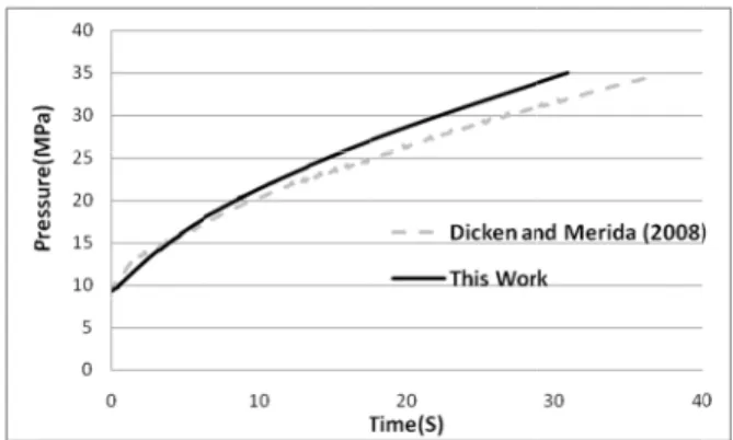
Figure 8 s red and num as pressure.
t step of the v f the physic e filling proc pared with d
Institute of hown in Fig n the results
omparing th this work du
presents the umbers durin hown in this at the inlet can be conclu so for the Ma uring the filli in the subson
riations of R drogen gas f
shows a com merical value It is clear
validation of cal propertie cess, the calc ensity values
Standards a gure 6, there
of this work
e density of uring the filli
variations o ng the hydro s figure, the
is on the or uded the flow ach number,
ing process t nic condition
Reynolds and filling proces
mparison betw s of the in-cy that the pre
f the method es of hydrog culated gas d
s obtained fr and Technolo
is good agr and NIST d
f hydrogen ing process a
of the Reyno ogen gas fill average Re der of 105. A w at the inle
as illustrated the inlet con n.
Mach numb ss.
ween the me ylinder avera essure increa
for gen
den-rom ogy ree-
den-gas and
olds ling yn- Ac-et is
d in
ndi-bers
eas-age ases
alm agr and
Fig in-the
ure ave agr giv
Fig in-for
enc of Fig fro par Me wa as can val
most linearl reement can d numerical
gure 8: Com -cylinder pres e compressed
Figure 9 sh ed and nume erage gas tem reement. For ven condition
gure 9: Com -cylinder tem r the compres
During the ce between t cylinder, he gure 10 the t om the comp
red with the erida (2008) all occurs at high as 60 k n be seen b lues.
ly within t n be observe
results.
mparing the n ssures of Dic d hydro.gen g
hows a comp erical time va
mperature, in r compresse ns, the tempe
mparing the n mperatures of ssed hydroge
filling, due the compres eat transfers
time variatio pressed gas to e experiment
). Clearly, th early times o kW. Again a between the
the cylinder ed between
numerical and cken and Mer gas filling pro
parison betw ariations of t ndicating rea d hydrogen erature rise ca
numerical and f Dicken and en gas filling
to the temp sed gas and from gas to on of the hea o the cylinde tal findings o he highest he of filling, wh relatively go measured a
r. Reasonab the measure
d the measure rida (2008) f ocess.
ween the mea the in-cylind asonably goo
gas under th an reach 55 K
d the measure Merida (200 process.
perature diffe the inner wa o the wall. at transfer ra er wall is com
of Dicken an eat flux to th hich can reac ood agreeme and numeric
ble ed
ed for
as-der
od he K.
ed 08)
er-all
In ate
th p m an ti al p m th o th p h th cy ad F w F th 2 th ca n an ch Figure 11 he inside and erature profi matic effect o nd carbon e ion of temp lmost the sa erature due t minium. How he filling pro f the lamina he cylinder r
erature. Con eat dissipatio he cylinder w
ylinder wall diabatic syst
Figure 10: H wall during th
Figure 11: M he cylinder w
Previous 008a, 2008b hat the initial ally the sam ificant effec nd charged m harged mas
describes th d outside wa files of the c of the therm poxy fibber erature with ame as that o
to the high t wever, due to ocess and th ate, the exter remains almo nsequently, it on from the i wall. Also, t l could be tem for the ty
Heat transfer he filling.
Model predicte wall during fi
studies (Far b, 2011, 201 l in-cylinder me as the am cts on the fin mass. Figure ss with am
he temperatur alls during th cylinder wall mal conductiv materials. T hin the alum of the in-cyl thermal cond o the relative he low therm rnal surface ost constant a t can be con in-cylinder f the in-cylind considered a ype III cylind
rate from in
ed temperatu illing.
rzaneh-Gord 2a, 2012b, 2
temperature mbient tempe nal in-cylind e 12 shows t mbient temp
re variations he fill. The te l show the d vity of the li The time var minium liner linder gas te ductivity of a ly fast speed mal conductiv temperature at ambient te ncluded most flow is stored der gas and
as a combin der.
-cylinder to
ure profile in
d et al., 20 2013a) show e, which is ba erature has s der temperat the variation erature, wh s of em- dra-iner ria-r is em- alu-d of vity e of em-t of d in the ned the n 007, wed asi- sig-ture n of hich ind per of tim exp cre int Fig fin cy in wh cal in-co con pro the cor tra inn ple the Th po fill ure res big fin p c
dicates an al rature increa hydrogen ve me as compa pected, the eases the fin teresting to n
gure 12: Eff nal in-cylinde
The heat c linder during
view of sa hich investig lly, failed to -cylinder gas st a lot in t nsists of two ocess of a h e CFD code rrelation for ansfer coeffic
ner convecti ete and inde e filling proc he complete
ssible to pre ling process The results ed values an sults also sh g effect on t nal in-cylinde
,
p cv Const
(kJ/kg
lmost linear ases. This me
ehicles reduc ared to the
rise in amb nal in-cylind note that this
fect of initial er temperatur
CONCL
haracteristic g the filling p
fety standar ated the fillin o model the
s and ambie time and res o parts. In th hydrogen cyl e fluent. Bas r predicting cient was de ve heat tran pendent ther cess was carr thermodyna edict the ther accurately an
were comp nd showed v howed that a the refueling er temperatur
NOMENC
tant pressure g K)
drop as the eans that the ces for fills i cold winter bient temper der gas temp
variation is
(ambient) te re and charg
LUSION
s of a hydr process are v rds. The pre
ng process th heat transfe ent. The CFD sources. The he first part, linder was m sed on the C the inner co eveloped. By nsfer coeffici rmodynamic ried out in th amic model rmal charact nd quickly. pared with p
very good ag ambient temp g process, p
re and charg
CLATURE
&volume sp
ambient tem e driving rang in hot summ
condition. A rature also i
perature. It almost linear emperature o ed mass. rogen onboa very importa evious studie hermodynam er between th D studies al
current wo the fast fillin modelled usin CFD results,
onvective he y knowing th
ient, the com c modelling he second pa ling makes teristics of th
d Inlet tube diameter (m)
g Gravitational acceleration (m/s2)
h Specific enthalpy (kJ/kg)
m Mass flow rate (kg/s)
u Internal energy (kJ/kg)
h Enthalpy (kJ/kg)
t time (seconds)
z Height (m)
A area (m2)
M Molecular weight (kg/kmol)
Ma Mach number
P Pressure (bar or Pa)
Q Heat transfer rate (kW)
Re Reynolds number
T Temperature (K or oC)
V Volume (m3)
Ve Velocity (m/s)
W Actual work (kJ/kg)
W Actual work rate (kW or MW)
x Thickness (m)
v Specific volume (m3/kg)
Greek Letters
Heat transfer convection coefficient (W/m2K)
Thermal conductivity (W/mK)
Isentropic Exponent
Density (kg/m3
)
Subscript
0 Rest condition
i initial or inlet condition
e exit condition
max maximum
p present time of filling process s start of filling process av average gen generation
C hydrogen on-board cylinder
CV control Volume
R reservoir tank
RA ratio
ambient
REFERENCES
Chan Kim, S., Hoon Lee, S., Bong Yoon, K., Ther-mal characteristics during hydrogen fuelling pro-cess of type IV cylinder. Int. J. Hydrogen Energ., 35, 6830-35 (2010).
Deymi-Dashtebayaz, M., Farzaneh-Gord, M., Noorali-poor, N., Rastgar, S., The full simulation of rapid refueling of a natural gas vehicle on-board cylin-der. Journal of Natural Gas Science and Engineer-ing, 21, 1099-1106 (2014).
Dicken, C. J. B., Merida, W., Measured effects of filling time and initial mass on the temperature distribution within a hydrogen cylinder during re-fuelling. J. Power Sources, 165, 324-36 (2007). Dicken, C. J. B., Merida, W., Modelling the transient
temperature distribution within a hydrogen cylin-der during refuelling. Nume. Heat Tra., Part A, 53, 1-24 (2008).
Farzaneh-Gord, M., Eftekhari, H., Hashemi, S., Ma-grebi, M., Dorafshan, M., The effect of initial conditions on filling process of CNG cylinders. The Second International Conference on Model-ling, Simulation, and Applied Optimization, Abu Dhabi, UAE, March 24-27 (2007).
Farzaneh-Gord, M., Compressed natural gas single reservoir filling process. Gas Int. Eng. and Manag., 48, 16-18 (2008a).
Farzaneh-Gord, M., Hashemi, S. H., Farzaneh-Kord, A., Thermodynamics analysis of cascade reser-voirs filling process of natural gas vehicle cylin-ders. World Applied Sci. J., 5, 143-149 (2008b). Farzaneh-Gord, M., Deymi-Dashtebayaz, M., Rahbari,
H. R., Studying effects of storage types on perfor-mance of CNG filling stations. J. of Nat. Gas Sci. Eng., 3, 334-40 (2011).
Farzaneh-Gord, M., Deymi-Dashtebayaz, M., Rahbari, H. R., Niazmand, H., Effects of storage types and conditions on compressed hydrogen fuelling sta-tions performance. Int. J. Hydrogen Energ., 37, 3500-09 (2012a).
Farzaneh-Gord, M., Deymi-Dashtebayaz, M., Rahbari, H. R., Effects of natural gas compositions on CNG fast filling process for buffer storage system. Oil, Gas Sci. Thec., 1-12 (2012b).
Farzaneh-Gord, M., Deymi-Dashtebayaz, M., Rahbari, H. R., Optimizing compressed natural gas filling stations reservoir pressure based on thermody-namic analysis. Int. J. Exergy, 10, 299-319 (2012c). Farzaneh Gord, M., Deymi-Dashtebayaz, M., Rahbari, H, R., Effects of gas types and models on opti-mized gas fuelling station reservoir's pressure. Braz. J. Chem. Eng., 30(2), 399-411 (2013a). Farzaneh-Gord, M., Deymi-Dashtebayaz, M.,
Opti-mizing natural gas fuelling station reservoirs pressure based on ideal gas model. Pol. J. Chem. Technol., 15, 88-96 (2013b).
International Standard Organization, Gaseous Hy-drogen and HyHy-drogen Blends Land Vehicle Fuel Tanks Part 1: General Requirements, ISO 15869 (2005).
International Standard Organization, Gas Cylinders-High Pressure Cylinders for the on-Board Storage of Natural Gas as a Fuel for Automotive Vehicles, ISO 11439 (2005).
Liss, W. E., Richards, M., Development of a natural gas to hydrogen fuelling station. Topical Report for US DOE, GTI-02/0193, Sept (2002).
Liss, W. E., Richards, M. E., Kountz, K., Kriha, K., Modelling and testing of fast-fill control algo-rithms for hydrogen fuelling. 2003 National Hy-drogen Association Meeting, March (2003). Liu, Y. L., Zhao, Y. Z., Zhao, L., Li, X., Chen, H. G.,
Zhang, L. F., Zhao, H., Sheng, R. H., Xie, T., Hu, D. H., Zheng, J. Y., Experimental studies on tempera-ture rise within a hydrogen cylinder during refuel-ling. Int. J. Hydrogen Energ., 35, 2627-32 (2010). Maus, S., Hapke, J., Ranong, N. C., Wuchner, E.,
Friedlmeier, G., Wenger, D., Filling procedure for vehicles with compressed hydrogen tanks. Int. J. Hydrogen Energ., 33, 4612-21 (2008).
Mohamed, K., Paraschivoiu, M., Real gas simulation of hydrogen release from a high-pressure cham-ber. Int. J. Hydrogen Energ., 30, 903-912 (2005). Newhouse, N. L., Liss, W. E., Fast filling of NGV
fuel containers. SAE paper -01-3739 (1999). Nooralipour-Nahavandi, N., Farzaneh-Gord, M.,
Numerical simulation of filling process of natural gas onboard vehicle cylinder. J. Braz. Soc. Mech. Eng. and Sci., 35, 247-256 (2013).
Oosthuizen, P. H., Carscallen, W. E., Compressible Fluid Flow. McGraw-Hill (1997).
Rigas, F., Sklavounos, S., Evaluation of hazards as-sociated with hydrogen storage facilities. Int. J. Hydrogen Energ., 30,1501-1510 (2005).
Schoenung, S., Ridell, B., Maack, M., Miles, S., His, S., A comparative study of hydrogen refuelling station experience. In: WHEC16-World Hydrogen Energy Conference, Lyon (2006).
Shipley, E., Study of natural gas vehicles during the fast fills process. Thesis for Master of Science, College of Engineering and Mineral Resources at West Virginia University (2002).
Thomas, G., Goulding, J., Munteam, C., Measure-ment approval and verification of CNG dispens-ers. NWML KT11 Report (2002).
Tzimas, E., Filiou, C., Hydrogen storage: State-of-the-art and future perspective. Petten: European Com-munities (2003).
Yang, J. C., A thermodynamic analysis of refuelling of a hydrogen tank. Int. J. Hydrogen Energ., 34, 6712-21 (2009).
Zhang, Y. J., Mao, Z. Q., Xie, X. F., Research and application of regenerative fuel cells. Prog. Chem., 18, 635-40 (2006).
Zhao, Y., Liu, G., Liu, Y., Zheng, J., Chen, Y., Zhao, L., Guo, J., He, Y., Numerical study on fast filling of 70 MPa type III cylinder for hydrogen vehicle. Int. J. Hydrogen Energ., 37, 17517-22 (2012). Zheng, J. Y, Li, L, Chen, R., High pressure steel
stor-age vessels used in hydrogen refuelling station. J. Press Vess-T ASME, 130, 1-3 (2008).