In vitro
Testing of a Novel Fibre-In-Fibre
Bioartificial Liver (FIF-BAL) With Bovine Plasma
Ali H. Alnaqbi and John D.S. Gaylor
Abstract – there is at present no specific treatment for acute liver failure other than transplantation and intensive care management. However, in severe cases of acute liver failure, bioartificial liver BAL support may provide a bridge to transplantation or would allow the patients liver to regenerate. If effective BAL can be developed, then they may greatly reduce the need for the transplant. Use of available biotechnology to design and in vitro evaluation of a novel Fibre-in-Fibre bioartificial liver has been described. It is basically a conventional fibre cartridge as a cells culture system with the addition of a second set of hollow fibres places within the lumens of the primary set. This arrangement provides three discrete compartments. Fresh bovine plasma was used to assess inner membrane fouling under dead-ended and cross-flow operating conditions. For this test the change in transmembrane pressure with time was determined. The results demonstrated that 0.3um pore size polypropylene inner fibre works best with cross-flow configuration. It was also found that before cells inoculation, cross flow should be run for 14-25 hours to establish steady state flux conditions.
Index terms - Hepatocytes; Artificial liver, Bioartificial liver; fibre in fibre, Bioreactor.
I. Introduction
Numerous groups worldwide are currently developing and evaluating BAL devices. Some designs have already reached clinical trials [1-3] whilst others are still under laboratory evaluation [4]. Some devices are perfused with whole blood [5] and others with plasma obtained by upstream plasmapheresis [6]. Many bioartificial liver support systems incorporate a means of oxygenating the perfusate in order to maintain cell function and viability. The oxygenation element may be integral within the reactor [7-9] or situated in series with the bioreactor in the circuit [10-11]. The latter is a more complicated alternative and costs more.
Coaxial (tricentric) hollow fibre bioreactors [TCHF] are new developed bioreactors for liver cells culture [4,12-14]. TCHF contain at least a hollow fibre within another hollow fibre to form at least third media or gas compartment. Previous theoretical mass transfer models [12] of this kind of bioreactor predicted similar results given by the oxygen consumption rates of hepatocytes [8]. This paper focuses in the design of a novel multi-coaxial hollow fibre bioreactor so-called fibre-in-fibre Bioartificial liver (FIF-BAL). Membrane permeability was studied to obtain the optimum physical operational parameters of the FIF using bovine plasma.
Ali Hilal Alnaqbi, 4 blackfan circle, Renal division, Brigham&Woman Hospital, Harvard Institute of medicine, Room 550, Boston 02115. Email : aalnaqbi@partners.org
John Gaylor, 106 Rottenrow, Bioengineering unit, Wolfson centre, University of Strathclyde, Glasgow G4 0NW. Email:
j.d.s.gaylor@strath.ac.uk
II. FIF-BAL bioreactor
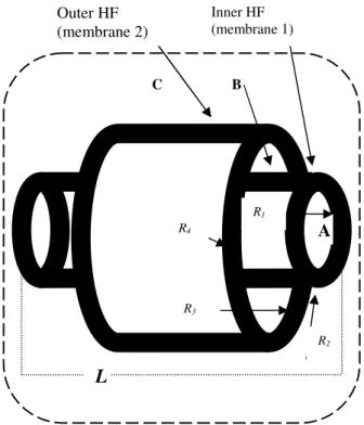
The FIF device fig. 1 has concentric cylindrical hollow fibres of length L. The inner fibre is of internal radius R1
and external radius R2. Fluid enters the lumen
(compartment A) of each fibre and some percolates through to leak into the cell region (compartment B) at r=R2. The
cell region extends from r=R2 to r=R3, the inside radius of
the outer fibre, whose outer radius is R4. We make that
assumption that the resistance to percolative flow through the outer fibre is so great that no plasma leaks through it. Beyond r=R4 is the shell space (compartment C) which
contains all the fibre pairs. It is filled with gas whose oxygen partial pressure is PG. The oxygen diffuses through
the outer fibre wall into the cell region. The cells therefore receive some oxygen by convection from the percolating fluid, and from the shell space by diffusion from r=R4 to
r=R3.
A.Equipments
A polypropylene hollow fibre (330- m ID, 630- m OD, 0.3- m pore size, SilasticTM tubing) was used as the inner fibre, a silicone rubber hollow fibre (1470- m ID and
1930-m OD, SilasticTM tubing) was used as the outer fibre, Decon (BDH Chemicals Ltd), Silicone Rubber Elastomer (RS 692-542,RS Components Ltd), male-male luer connector (Vygon Ltd), Araldite (Ciba Araldite Rapid, Bostik), centrifuging system(Mistral 4L, FK240, MSE, England), plate viscometer (Wells-Brookfield, Synchro-lectric, USA), Bromocresol Green (AB 362, Randox Chemical Company). Construction of the FIF bioreactor consisted of six stages to attach both ends. Quality assurance was performed at each of the stages of the bioreactor construction to check for any cracks in the housing material once it comes from the workshop.
B. Flow configurations
The main factors that influence fouling are the hydrodynamics of the process, the physiochemical properties of the filtration membrane and of the feed solution. Therefore, using fresh bovine plasma, membrane fouling and the effect of the flow configuration will be analysed for the FIF bioreactor. Although, bovine plasma contains complex protein mixtures, in this study we are assuming that the protein fouling is caused primarily by albumin.
One goal of this study is to compare dead-ended and cross-flow configurations by monitoring the change in
transmembrane pressure and permeate flux with time for a constant feed flow rate using a novel FIF bioreactor. Permeability of the bioreactors will be examined using distilled water and will be compared with the clean (un-used with plasma)bioreactor. The comparison will show if there is any better behaviour of the FIF bioreactor depending on the flow configuration. The dead-ended flow configuration will be used as well to ascertain the time at which the inner fibre becomes completely fouled and no more plasma can pass. This is important when cells are filled in, since in cell culture in hollow fibre bioreactors, pore blockage by cell debris is one of two major factors (the other one is adsorption of proteins) which may contribute to the fouling of the membranes.
C. Total Resistance Calculation
The total resistance of membrane has been used to study membrane polarisation and the effect of the flow configuration on membrane fouling [13]. In this study we have used the filtration flow rate (Qf) and the pressure data
to calculate the total resistance according to Darcy’s law [23]:
R tot = [(A Ptm )/ Qf p]
Where: R tot is total filtration resistance (m-1).
Ptm is the transmembrane pressure driving force (Pa).
A is the filtration area (m2). p is the permeate viscosity (Pa s). Qf is the filtration flow rate (m
3 /s)
The summation of the resistivity of the clean membrane (Rm) and resistivity of protein fouled membrane (Rf) is the
total resistance:
Rf = R tot - Rm
III. Theory and method:
The hollow fibre permeability will decrease with cell culture media because of membrane fouling whereby macromolecules in the media will clog the membrane pores. In dead-ended configuration, plasma perfusate will be forced into Comp A and radially filtered towards Comp B across the polypropylene hollow fibre, and removed at outlet port OB. With time the permeate flux will decline and ultimately become vanishingly small. This is a result of the increased hydraulic resistance to plasma transport due to protein clogging of the membrane pores. The time course of the decline in the filtration flux has been used by Robertson and Kim [25] for an approximation of the length of time required to achieve moderate to high levels of cell concentration in the interstitial region. In our study, the increase in transmembrane pressure and total membrane resistance over a period of time will be used to detect the effect of the flow configuration on the FIF bioreactor performance. In order to obtain additional insights into membrane fouling in the FIF bioreactor, albumin concentrations will be measured in the inlet (feed) and outlet (permeate) flow streams.
C B
Fig. 1 - Functional element of FIF bioreactor. For clarity, the figure is not drawn to scale. In our device L> R4.
A
R2 R1
R3 R4
L
Gas in Gas out
Perfusate Perfusate
Perfusate Perfusate
Cross configuration.
Dead-ended Configuration
Fig. 2 - FIF bioreactor flow configurations in, upper, cross flow configuration and, lower, dead-ended configuration.
Outer HF (membrane 2)
The average transmembrane pressure
P
tm (ultrafiltration from Comp. A to Comp. B) will be determined as follow: from mass conservation and assuming no seal leakage, the filtrate flow rate (Qf) will equal the inlet flow (Qi). Since Comp B is open to atmosphere, the hydrostatic pressure in compartment B will be zero. Therefore PB = 0 mmHg. Assuming that the pressure drop due to flow along the fibre x-axis is small compared to that across the fibre wall then the pressures at IA and OA will be equal. Therefore h1AB = h2AB .The mean transmembrane pressure,
P
tmis therefore given by:
P
tm = (h1AB + h2AB)/2 - PB= ( h1AB + h2AB)/2 - 0
= h1AB
The filtration flow rates, Qf were determined by timed
volume collection in the waste reservoir. The flux was calculated by dividing Qf by the inner membrane area
(membrane 1). Measurements were taken at 0, 1, 2, 4, 5, 6, 24, 46 and 51 hours. All the experiments were carried out at room temperature (20-23oC). The plasma viscosity was measured according to that day temperature. Fresh bovine plasma and an unused bioreactor were loaded into the experimental apparatus for each test. The permeate was recycled to the feed reservoir in order to conserve plasma volume and maintain a constant feed concentration. The albumin concentration was also used to detect the membrane fouling, by plotting the permeate albumin concentration versus time.
A. Plasma Preparation:
Plasma was prepared from abattoir-sourced, fresh bovine blood, anti-coagulated with disodium EDTA (2 g/l). The blood was filtered through a nylon mesh to remove larger emboli and particulate matter and centrifuged at 1700 rev/min for 30 minutes. The supernatant plasma was removed and re-centrifuged 30 minutes at 1700 rev/min. Plasma viscosity was measured using a cone and plate viscometer. The viscometer was calibrated against distilled water at 37oC. The plasma viscosity corresponding to the room temperature, T oC was determined from the following relationship:
water T
plasma T
=
3737
µ
µ
µ
µ
B. Albumin concentration measurements:
Plasma albumin concentrations were determined by the Bromocresol Green (BCG) method. 10 µl of plasma was
added to 3 ml of diluted BCG reagent solution and the absorbance measured in the a spectrophotometer at 630 nm wavelength. The absorbance of an albumin standard (45g/l) was also measured with BCG reagent as a blank. The albumin concentration of the plasma sample was calculated as follows:
Albumin Concentration = (Asample / Astandard) x Standard concentration .
IV. Results
Previous studies with similar hollow fibre configurations have shown that isolated rat hepatocytes die within few hours depending on the flow configuration and that there is a higher rate of survival with the radial flow configuration [22]. Typical of in vitro cultures of primary hepatocytes, no cell growth was observed over several days [15]. They explained the cause for this was both inner hollow fibre membranes fouling as well as the flow configuration. In this study, bovine plasma filtration experiments were performed with dead-ended and cross-flow configurations in order to assess the effectiveness of these configurations in reducing the inner membrane concentration polarisation.
A. Dead-ended flow configuration
The performance of the FIF bioreactor operated with the dead-ended configuration is shown in fig. 3. These results for a constant filtration flux of 17ml/min. Due to protein concentration polarisation the transmembrane pressure drop, Ptm, increases very rapidly with dead-ended flow. [Comparative data is given for axial-flow where concentration polarisation occurs at a much lower rate due to shearing forces tangential to the filtering surfaces]. A decrease in the Ptm was noticed after 200 minute for around 10 minutes, then stayed constant for 200 minutes, and then increased again after 400 minutes. Another decrease was noticed between the 300 minutes and 350 minutes. This was confirmed by the decrease in the permeate albumin concentration at the same time fig. 3.
0 20 40 60 80 100 120 140 160 180
0 10 20 30 40 50 60
Tim e (hours)
T
ra
n
s
m
e
m
b
ra
n
e
p
re
s
s
u
re
d
ro
p
(
m
m
H
g
)
Cross-flow
Dead-ended flow
Fig. 3 -Trend in transmembrane pressure drop with time for dead-ended and cross-flow configuration in the FIF bioreactor.
0 5 10 15 20 25 30 35 40 45
0 2 4 6 8 10
Time (hours)
A
lb
u
m
in
c
o
n
c
e
n
tr
a
ti
o
n
(g
/l
)
Fig. 4- Albumin concentration in the permeate with the dead-ended flow before the cross flow established.
0 5 10 15 20 25 30
0 100 200 300 400
transmem brane pressure drop (m mHg)
fi
lt
ra
ti
o
n
f
lo
w
r
a
te
(
m
l/
m
in
)
clean FIF bioreactor
Post dead-ended flow
Post cross flow
Fig. 5- Ptm for different filtration flow rates with three FIF bioreactors. One bioreactor was unused (clean) and the other two were used for the dead-ended and cross-flow configurations.
B. Cross flow configuration results
In the cross flow configuration experiments Ptm was relatively constant and compared to the dead-ended flow study was much more stable until steady state radial flow was reached. A significant flux decline was observed during the first 25 hours of the experiment followed by a relatively stable flux for about 15 hours leading to steady state radial flow after 50 hours Fig. 6. The difference in calculated total resistance Fig. 7 was within one order of magnitude after 50 hours comparing to the dead-ended results. This agrees with other typical fouling studies with plasma [26], which indicated that there was a relatively minor membrane fouling with cross-flow comparing to dead-ended flow configuration.
The albumin concentration in permeate was also studied and results are shown in fig. 8 for the cross-flow configuration. The change in albumin concentration with time follows that of Ptm. Higher protein reflection by the membrane being associated with higher fouling and as a consequence increased Ptm.
0.000 10.000 20.000 30.000 40.000 50.000 60.000
0 10 20 30 40 50 60
Time (hours)
fl
u
x
(
m
l/
m
in
m
2)
Fig. 6- Filtration flux during cross flow experiment
.
0.E+00 1.E+07 2.E+07 3.E+07 4.E+07 5.E+07 6.E+07 7.E+07
0 10 20 30 40 50 60
Time (hours)
T
o
ta
l
re
s
is
ta
n
c
e
(
1
/m
)
Fig. 7- Total resistance of the hollow fibre membrane with cross flow.
cross flow
0 2 4 6 8 10 12 14 16
0 10 20 30 40 50 60
Time (hours)
A
lb
u
m
in
c
o
n
c
e
n
tr
a
ti
o
n
(
g
/l
)
V. Discussion
A novel FIF bioartificial liver was developed and tested for liver cells culture. Permeability of FIF bioreactor is a critical physical characteristic of the hollow fibre membranes used in this device. The relationship between the flow rate Q and the hydrostatic pressure can predict the hydraulic characteristics of the membranes. It is very important that 90% of plasma enters the annulus by the 20% of the axial length of the bioreactor for detoxification, and at the same time avoiding building high hydraulic pressure in the annulus by concentration polarisation. Hydrophobic effects between the solute and membrane surface are a significant factor with polypropylene material. In addition, this concentration polarisation resulting from the membrane fouling will decrease the local oxygen solubility at the membrane surface.
Membrane permeability is an important parameter when discussing concentration polarisation [21]. Macdonald et al [13] concluded from a study of hepatocyte function in a similar FIF bioreactor that the relatively low hydraulic permeability of the inner membrane was a primary cause of dead hepatocytes and likely due to membrane fouling. As stated above, the goal of the fouling experiments was to asc
ertain the influence of the flow configuration on the FIF bioreactor performance. Dead-ended flow and cross-flow configurations were studied and the results are shown in Fig. 3 to 5 and in Fig. 6 to 8, respectively. Transmembrane pressures during the time course of the experiments was significantly lower with the cross flow configuration. For cross flow, the flux time course (until a steady state flux was obtained) was in agreement with other typical bioreactor membrane fouling studies [13,16]. Although there was an initial decrease in the flux due to fouling, a plateau was then followed over which the flux remains steady due to constant radial flow rate. This initial decrease was also characterised by a decrease in the permeate albumin concentration. We can conclude from the above experiments that the chosen 0.3
µ
m pore size polypropylene inner hollow fibre works best with cross flow configuration. Before any cells are seeded in the bioreactor; account should be taken for any different medium; and cross-flow should be run for 14-25 hours to establish steady state flux conditions. Moreover, the change in the medium characteristics used to obtain that steady state should be taken into account. Therefore, it is necessary for the medium to be changed prior to any cell inoculation to achieve the desired hormonal concentration required by the hepatocytes for proper function. FIF device has a separate integral oxygenation in the outermost compartment by the creation of a third space namely compartment C. This Integral oxygenation compartment should be easily oxygenate the cells in the annulus to levels higher than 2 mmHg, ensuring that the cells are functional and viable. This work does not consider mass transfer rates of oxygen from compartment C to compartments A and B. mathematical modelling of oxygen is one way to study oxygen transfer rate OTR. The mass transfer rates of oxygen and glucose have been modelled mathematically in several studies and their concentration profiles throughout the cell mass have been calculated. A mathematical model is only as good as the assumptions on which it is based. If the assumptions misrepresent the real device, or if the real device behaves less consistently than isassumed in the model, discrepancies will arise between the model’s predictions and any real behaviour of the device. Nevertheless, such modelling facilitates understanding of the relationship between mass transfer and other bioreactor parameters, such as the membrane and medium composition [27] and cell mass density [25].
Diffusion and convection are the two main mechanisms for mass transport. Convective transport through a membrane or tissue is normally assumed to follow Darcy’s Law which relates the velocity of fluid flow to a hydraulic pressure gradient. For hollow fibre bioreactors, most of the mathematical modelling is based on a Krogh cylindrical model [28]. A work on developing a mathematical modelling of flow and oxygen transport in the FIF BAL is done and will be published soon. We extended the Krogh cylinder model by including one more zone for oxygen transfer from a gas compartment. The model has many assumptions in common with the Hay et al [29] model. However, the effect of the gas compartment on the OTR is a new and beneficial development.
References
[1] Mazariegos GV, Kramer DJ and Lopez RC. (2001),Safety observations in the phase I clinical evaluation of the Excorp medical BLSS after the first four patients. ASAIO . Vol. 47: pp 471-475.
[2] Gerlach JC, Lemmens P, Schon M, Janke J, Rossaint R, Busse B, Puhl G and Neuhaus P. (1997). Experimental evaluation of a hybrid liver support system. Transplantation Proceedings. Vol 29 : pp 852.
[3] Watanabe FD, Arnaout WS, Ting P, Navarro A, Khalili T, Kamohara Y, Kahaku E, Rozga J and Demetriou AA. (1999). Artificial liver.
Transplantation proceeding. Vol. 31. (2): pp 371-373.
[4] Wolfe SP, Hsu E, Reid LM and Macdonald JM. (2002). A novel multi-coaxial hollow fibre bioreactor for adherent cell types. Part 1: Hydrodynamic Studies. Biotechnology and Bioengineering.Vol. 77 (1) : pp 83-90.
[5] Sussman NL Lake J R, (1996a). Treatment of hepatic failure: Current concepts and progress towards liver dialysis. Scandinavian Journal of Kidney Diseases. Vol.27 (5): pp 605-621.
[6] Flendrig LM, Chamuleau RAFM, Maas MAW. (1999). In vivo evaluation of a novel bioartificial liver in rat with complete liver ischemia: treatment efficacy and species specific alha GST as a first attempt to monitor hepatocyte viability. Journal of Hepatology; Vol. 30(2): pp 311-320.
[7] Gerlach JC. (1996a). Development of a hybrid liver support system: a review. International Journal of Artificial Organs. Vol 19: pp 645-654. [8] Smith MD, Smirthwaite AD, Cairns DE, Cousins RB and Gaylor JDS (1996). Techniques for measurement of oxygen consumption rates of hepatocytes during attachment and post-attachment. International Journal of Artificial Organs. Vol. 19: pp 36-44.
[9] Macdonald JM, Griffin J, Kubota H, Griffith L, Fair J, Reid LM,. (1999). Bioartificial livers In: Kuhtreiber W, Lanza RP, Chick WL, editors.
Cell encapsulation technology and therapeutics. New York: Birkhauser Boston. pp 252-286.
[10] Millis JM, Cronin DC, Johnson RC, Conjeevaram MD, Conlin C, Trevino S and Maguire P. (2002). Initial experience with the modified extracorporeal Liver Assist Device ELADTM for patients with fulminant hepatic failure: system modifications and clinical impact. Transplantation. Vol 74, (12): pp 1735-1745.
[11] Mazariegos GV, Patzer JF, Lopez RC, Giraldo M, Devera ME, Grogan TA, Zhu Y, Fulmer ML, Amiot BP and Kramer DJ. (2002). First clinical use of a novel bioartificial liver support system (BLSS). American Journal of Transplantation. Vol. 2 : pp 260-266.
[12] Cima LG, Blanch HW and Wilke CR (1990). A theoretical and experimental evaluation of a novel radial-flow hollow fibre reactor for mammalian cell culture. Bioprocess Engineering. Vol 5: pp 19-30. [13] Macdonald JM, Wolfe SP, Roy-Chowdhury I, Kubota H, Reid LM (2001). Effect of flow configuration and membrane characteristics on membrane fouling in a novel multicoaxial hollow fibre bioartificial liver.
Annals N Y Academic of Sciences. Vol 944: pp 334-343.
[15] Custer LM. (1988). Physiological studies of hybridoma cultivation in hollow fibre bioreactors, PhD dissertation, University of California. Berkeley.
[16] Belfort G, Davis R and Zydney A. (1994). The behaviour of suspensions and macromolecular solutions in cross flow microfiltration. Journal of Membrane Science. Vol. 96. : pp 1-58.
[17] Tharakan JP, Chau Pc. (1986a). A radial flow hollow fibre bioreactor for a large scale culture of mammalian cells. Biotechnology and Bioengineering. Vol 28: pp 329-342.
[18] Meireles M, Imar PA and Anchez VS. (1991). Albumin denaturation during ultrafiltration: Effect of operating conditions and consequences on membranes fouling. Biotechnology and Bioengineering. Vol. 38 : pp 528-534.
[19] Mochizuki S and Zydney AL. (1993). Theoretical analysis of pore size distribution effects on membrane transport. Journal of Membrane Sciences. Vol. 82 : pp211-227.
[20] Langsdorf LJ and Zydney AL. (1994). Effect of blood contact on the transport properties of haemodialysis membranes. A two layer membrane model. Blood Purification. Vol. 12 : pp 292-307.
[21] Jaffrin MY, Ding LH and Khari CP. (1997). Effect of ethanol on ultrafiltration of bovine albumin solutions with organic membranes.
Journal of Membrane Science. Vol. 124 : pp 233-241
[22] Macdonald JJ, Griffin JP, Kubota H, Griffith L, Fair J and Reid LM. (1999). Cell encapsulation technology and therapeutics, New York: Birkhuser Boston, Bioartificial livers in. pp : 252-286.
[23] Pronk W, Boswinkel G, Vant R (1992). parameters influencing hydrolysis kinetics lipase in hydrophilic membrane bioreactor. Enzyme Microbiology Technology. Vol. 14 : pp 214.
[24] Tharakan JP, Chau Pc. (1986b). Operation and pressure distribution of immobilised cell hollow fibre bioreactors. Biotechnology and Bioengineering. Vol. 28: pp 1064-1071.
[25] Robertson CR and Kim LH (1985). Dual aerobic hollow fibre bioreactor for cultivation of streptomyces aerofaciens. Biotechnology Bioengineering. Vol. 27. pp 1012-1020.
[26] Guell C and Davis RH. (1996). Membrane fouling during microfiltration of protein mixtures. Journal of Membrane Science. Vol. 119: pp 269-284.
[27] Piret JM and Cooney CLC. (1990). Mammalian cell and protein distributions in ultrafiltration hollow fibre bioreactors. Biotechnology and Bioengineering. Vol 36 : pp 902-910.