Brazilian Journal of Physics, vol. 34, no. 2B, June, 2004 565
TMR Effect in a FM-QD-FM System
F. M. Souza
1, J. C. Egues
1,2
, and A. P Jauho
3 1Departamento de F´ısica e Inform´atica, Instituto de F´ısica de S˜ao Carlos, Universidade de S˜ao Paulo, 13560-970 S˜ao Carlos, S˜ao Paulo, Brazil
2
Department of Physics and Astronomy, University of Basel, Klingelbergstrasse 82, CH-4056 Basel, Switzerland
3
Mikroelektronik Centret, Danmarks Tekniske Universitet, DK-2800 Kgs. Lyngby, Denmark
Received on 31 March, 2003
Using the Keldysh nonequilibrium technique, we study current and the tunnelling magnetoresistance (TMR) in a quantum dot coupled to two ferromagnetic leads (FM-dot-FM). The current is calculated for both parallel and antiparallel lead alignments. Coulomb interaction and spin-flip scattering are taken into account within the quantum dot. Interestingly, we find that these interactions play a contrasting role in the TMR: there is a parameter range where spin flip suppresses the TMR, while Coulomb correlations enhance it, due to Coulomb blockade.
1
Introduction
Tunnelling magnetoresistance (TMR) describes the change in the resistance of a FM-insulator-FM system when the fer-romagnet leads switch their relative polarization alignments from a parallel (P) to an anti-parallel (AP) configuration. This effect was discovered by Julliere [1] in a Co/Ge/Fe junction; he observed a resistance change∆R/Rof nearly 14% at 4.2K and zero applied bias. This effect, however, was significantly suppressed when a voltage of few meV was applied across the junction. In 1995 Mooderaet al.[2] succeeded in significantly improving the TMR ratios: values of∆R/Rclose to 11% at 295K and 24% at 4.2K were re-ported. In addition,∆R/Rremained almost independent of the dc bias up to about 100 mV in this experiment. The TMR is important for several technological applications. These encompass magnetic-field sensors [3], hard-disk read heads [4], and non-volatile storage devices [5].
Here we use a quantum dot in between the ferromagnetic leads, instead of the usual insulator layer as in the standard TMR setup. In a FM-QD-FM system the quantum dot plays a role in the transport properties, thus giving rise to new physics not present in the usual FM-I-FM junction. For ex-ample, this system can exhibit Coulomb blockade [6]-[8] and the Kondo effect [9]-[11]
In this work, we are particularly interested in the in-terplay of spin-flip scattering and electron-electron interac-tion effects on the TMR. We assume that both the spin flip and Coulomb correlations act only within the dot. In ad-dition, the tunnelling processes from the leads into the dot and vice versa are assumed spin conserving [12]. Our ap-proach is based on the Keldysh nonequilibrium technique [13]. Within this framework, we develop a set of coupled equations involving the retarded, advanced, and lesser Green
functions. We then express the current in the leadsη = L (Left), R (Right) for both P and AP configurations in terms of these Green functions. We calculate the TMR ratio from the usual definition
T M R=IP−IAP
IAP
, (1)
whereIP (IAP) is the current in the parallel (antiparallel) configuration.
Our main results are as follows. We find that both the Coulomb interaction and the spin flip scattering within the dot play crucial roles in the transport properties of our FM-QD-FM system. On the TMR, for instance, spin flip tends to wash out this effect, which is consistent with experimental findings [12]. On the other hand, Coulomb interaction tends to enhance the TMR in the Coulomb blockage regime [14].
dot
ΓL ΓR
eV=µ − µ
L R
FM lead FM lead
or
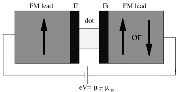
Figure 1. Schematics of the system investigated: two ferromag-netic leads attached to a quantum dot via tunnelling barriers. An applied biasV across the system gives rise to a lead chemical po-tentials imbalance,eV =µL−µR, which produces a net current
566 F. M. Souzaet al.
2
Model Hamiltonian
Our FM-QD-FM system consists of two FM leads coupled to a quantum dot via tunnelling barriers, Fig. 1, with tun-nelling ratesΓL
σ andΓRσ, whereσis the spin index andL andR denote left and right leads, respectively. The lead chemical potentials differ byeV =µL−µRdue to the ap-plied biasV (heree >0). The dot is supposed to have only one spin-degenerate levelǫd in the absence of interactions. We assume a linear voltage drop across the system so that ǫd = ǫ0−eV /2, whereǫ0is the energy level position for
zero bias. This assumption does not account for charging effects in the dot, which in general give rise to a non-linear variation ofǫdwith the bias voltage [15].
Hamiltonian.The FM-QD-FM Hamiltonian we use has the form
H =HL+HD+HR+HT. (2) In the above, HL = PkσǫkσLc†kσLckσL (HR) describes the left (right) lead; the operatorckσL(c†kσL) destroys (cre-ates) an electron in the lead L with wave vector k and spin component σ, whose energy dispersion isǫkσL. For a parabolic-band ferromagnet (“Stoner model”), ǫkσL = ~2
k2
/2m+σ∆, where ∆ denotes the exchange-induced spin splitting of the bands.
The second term in Eq. (2) is the dot Hamiltonian HD = Pσǫdd†σdσ+U n↑n↓+R(d†↑d↓+d†↓d↑)withdσ (d†
σ) being the destruction (creation) operator for electrons in the dot,U the Coulomb interaction strength, andR the spin flip rate. The last term in (2) is the tunnelling Hamilto-nianHT =Pkση{tkσc†kσηdσ+h.c.}, wheretkσis the cou-pling matrix. We neglect spin flip process in the tunnelling process, hencetkσis spin conserving and does not mix dif-ferent spin components. Note thatHT drives the system out of equilibrium when an external voltage is applied.
3
Non-equilibrium current
The current in leadηis given byIη=−ehN˙ηi, whereNη = P
kσc
†
kσηckσηis the total electron number operator andh...i denotes a thermodynamic average. Using the Heisenberg equation of motion, we find Iη = −eih[HT, Nη]i. This average is carried out in the non-equilibrium framework, which yields [16]
Iη=ie Z dω
2π X
σ
Γη
σ[G<σσ+nη(Grσσ−Gaσσ)], (3)
whereΓη σ= 2π
P
k|tkσ|2δ(ǫ−ǫkση)is the line-width func-tion, which is proportional to the density of statesρη
σ(ǫ)of the leadη. The functionΓη
σdefines also the tunnelling rates between the leads and the dot. nη(ω)is the Fermi distribu-tion funcdistribu-tion of the leadη. Gr
σσ,Gaσσ, andG<σσ are the re-tarded, advanced, and lesser Green functions, respectively. They are all obtained via analytical continuation [17] and Fourier transform of the contour time-ordered Green func-tionG(τ, τ′) = −ihT
cdσ(τ)d†σ(τ′)i, whereTc is the con-tour time-ordering operator andτ andτ′are complex times
running along the Keldysh contour. From Eq. (3) we deter-mine the current in both P and AP cases, and then calculate the TMR which we discuss in the next section. Note that current is strictly conserved in our system, i.e.,IL =−IR which gives eitherIP orIAP depending on the lead align-ment considered.
In our actual calculation, we assume that the density of states in the leads ρσ(ǫ) is energy independent (wide-band limit) and equal toρσ(ǫF), whereǫF is the Fermi en-ergy. Note that the spin imbalance in the leads translates intoρ↑(ǫF) 6= ρ↓(ǫF)which in turn yieldsΓL↑ 6= ΓL↓
(in-cidentally, this gives rise to spin-polarized transport in the system). Hence, spin up electrons tunnel into the dot with a rate different from that for spin down electrons. More ex-plicitly, in the parabolic band model the line-width function becomes
ΓLσ = Γ0
r
1 +σ∆ ǫF
. (4)
By Taylor expanding ΓL
σ in ∆/ǫF < 1 we find ΓLσ ≃
Γ0(1 +σp)to lowest order, wherep= ∆/2ǫFis the degree of polarization of the leads andΓ0is the strength of lead-dot
coupling. To simulate the P and AP alignments in our calcu-lation, we useΓR
σ = ΓLσ andΓRσ = ΓLσ¯, respectively, where
σ=−σ.
4
Results
In our numerical calculation we setΓ0=10µeV andp= 0.4
(40%). The temperature used iskBT = 0.17meV and the charging energy isU = 1meV. We takeµL = 0as the ref-erence of zero energy so thatµR =−eV. We also assume ǫ0 = 0.25meV. For zero bias we haveǫ0> µL, so that the
dot is only slightly populated by electrons in this case. This small population arises from thermal excitations. The elec-trons start to resonantly tunnel into the dot when the level ǫdlines up withµL(the emitter lead), thus generating a net current.
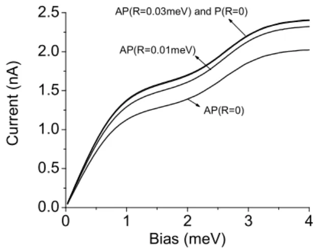
Figure 2 shows the average currentIagainsteV for both the P and AP cases and different spin flip rates. Note that the current increases initially due to the emergence of the on-resonance condition ǫd = µL. For temperatures much smaller than the level width, this enhancement of the cur-rent is very sharp and happens exactly at ǫd = µL. But here we use a temperaturekBTmuch greater thenΓσ(“level width”), so this enhancement is broadened as seen in Fig. 2. When the levelǫdis belowµLthe current tends to saturate in the Coulomb blockade regime between 1 and 2 meV in Fig. 2. However, at even higher biases the level ǫd +U comes in resonance with the emitter conduction band, thus giving rise to a new enhancement of the current. The cur-rent finally saturates when the two levelsǫdandǫd+U are belowµL. Note that the second resonance involves double occupancy in the dot.
Brazilian Journal of Physics, vol. 34, no. 2B, June, 2004 567
processes. Note also thatIAP tends toIP as the spin flip rate increases.
Figure 2. Current againsteV for both the P and AP alignments and three spin flip rates. The two broad steps correspond to the levels
ǫdandǫd+U. Observe thatIP > IAP. This is due to the
resis-tance difference between the two magnetic configurations. When spin flip takes place this difference is reduced, thus revealing that spin flip suppresses the resistance difference between the P and the AP cases.
Figure 3. Tunnelling magneto resistance againsteV for three spin flip rates. The TMR is strongly suppressed due to spin flip, ap-proaching zero forR= 0.03meV.
Figure 3 shows the TMR signal for three spin flip rates. ForR = 0the TMR is enhanced in the bias range
[0.5,2.5meV], peaking at 1.5 meV. This enhancement is due to Coulomb correlations which shift one spin channel to ǫ+U, thus reducing the current which flows through the levelǫ, and increasing the resistance of the system. For R= 0.01meV the TMR is significantly suppressed and for R = 0.03meV it is close to zero. This shows that spin flip washes out the TMR. The effect of spin flip scattering on the TMR was reported experimentally in a FM-I-FM system,
where the spin flip takes place in the insulator layer [12]. This experiment shows that the TMR is suppressed due to spin flip. Even though our system is different than that stud-ied experimentally, the role of spin flip – which in our sys-tem is strictly confined to the dot – on the TMR presents a similar trend.
5
Conclusion
We have briefly described the effects of spin-flip scattering and the electron-electron interaction on the TMR of a quan-tum dot coupled to two ferromagnetic leads. We find thatIP is essentially insensitive to spin flip, whileIAP is dramati-cally affected by these processes thus tending toIP as the spin flip rates increase. Hence spin flip suppresses TMR. On the other hand, electron-electron interaction in the dot enhances the TMR due to Coulomb blockade.
This work was supported by FAPESP/CAPES (FMS), the Swiss NSF, DARPA/ARO and the NCCR Nanoscience (JCE).
References
[1] M. Julliere, Phys. Lett. A54, 225 (1975).
[2] J. S. Moodera, L. R. Kinder, T. M. Wong, and R. Meservey, Phys. Rev. Lett.74, 3273 (1995).
[3] M. Tondraet al., J. Appl. Phys.83, 6688 (1998). [4] K. Sinet al., J. Appl. Phys.89, 7359 (2001). [5] S. S. P. Parkinet al., J. Appl. Phys.85, 5828 (1999). [6] H. Br¨ucklet al., Phys. Rev. B58, R8893 (1998).
[7] K. Ono, H. Shimada, and Y. Ootuka, J. Phys. Soc. Jpn.66, 1261 (1997).
[8] L. F. Schelpet al., Phys. Rev. B56, R5747 (1997).
[9] P. Zhang, Q. K. Xue, Y. Wang, and X. C. Xie, Phys. Rev. Lett.
89, 286803 (2002).
[10] B. Dong, H. L. Cui, S. Y. Liu, and X. L. Lei, cond-mat/0303093.
[11] R. L´opez and D. S´anchez, Phys. Rev. Lett.90, 116602 (2003).
[12] For a non-conserving tunnelling process in a FM-I-FM junc-tion see R. Jansen and J. S. Moodera, J. Appl. Phys.83, 6682 (1998) and A. Vedyayevet al., Eur. Phys. J. B25, 5 (2002). [13] L. V. Keldysh, Soviet. Physics JETP20, 1018 (1965).
[14] An enhancement of the TMR between the Coulomb steps of aI−V characteristic curve was reported by J. Barna´set al.,
Phys. Rev. B62, 12363 (2000).
[15] A more general model will be published elsewhere.
[16] H. Haug and A. P. Jauho,Quantum Kinetics in Transport and Optics of Semiconductors, Springer Solid-State Sciences123
(1996).