Journal of Applied Fluid Mechanics, Vol. 9, No. 4, pp. 2083-2095, 2016. Available online at www.jafmonline.net, ISSN 1735-3572, EISSN 1735-3645.
Numerical Investigation of Nozzle Geometry Effect on
Turbulent 3-D Water Offset Jet Flows
N. Mohammadaliha
1, H. Afshin
2†and B. Farahanieh
21 School of Mechanical Engineering, Sharif University of Technology, Tehran, Iran 2 School of Mechanical Engineering, Sharif University of Technology, Tehran, Iran
†Corresponding Author Email: [email protected] (Received August 7, 2013; accepted October 10, 2015)
A
BSTRACTUsing the Yang-Shih low Reynolds k- turbulence model, the mean flow field of a turbulent offset jet issuing from a long circular pipe was numerically investigated. The experimental results were used to verify the numerical results such as decay rate of streamwise velocity, locus of maximum streamwise velocity, jet half width in the wall normal and lateral directions, and jet velocity profiles. The present study focused attention on the influence of nozzle geometry on the evolution of a 3D incompressible turbulent offset jet. Circular, square-shaped, and rectangular nozzles were considered here. A comparison between the mean flow characteristics of offset jets issuing from circular and square-shaped nozzles, which had equal area and mean exit velocity, were made numerically. Moreover, the effect of aspect ratio of rectangular nozzles on the main features of the flow was investigated. It was shown that the spread rate, flow entrainment, and mixing rate of an offset jet issuing from circular nozzle are lower than square-shaped one. In addition, it was demonstrated that the aspect ratio of the rectangular nozzles only affects the mean flow field of the offset jet in the near field (up to 15 times greater than equivalent diameter of the nozzles). Furthermore, other parameters including the wall shear stress, flow entrainment and the length of potential core were also investigated. Keywords: 3D offset jet; Numerical simulation; Aspect ratio; Rectangular nozzle; Circular nozzle.
N
OMENCLATUREAR nozzle aspect ratio De equivalent nozzle diameter
Dj diameter of circular nozzle
h height of nozzle center I Intensity
k mean turbulence kinetic energy per unit mass P pressure
Q total mass flux at location of x in the streamwise direction
Qin total mass flux at inlet plane of jet
U Time-averaged velocity component in the x-direction
u’
i velocity fluctuations in the xi direction
ui velocity components in the xi direction
Uj inflow velocity in the x-direction
Umax maximum streamwise velocity in each
longitudinal section uτ friction velocity
x, y, z coordinates xi directions
y+ non-dimensional distance based on local
cell fluid velocity
Y0.5 jet half width in the wall-normal
direction
Ym the location of maximum streamwise
velocity in the y-direction
Z0.5 jet half width in the lateral direction
µ dynamic viscosity
ij kronecker delta
turbulent dissipation rate
ν kinematic viscosity
νT turbulent kinematic viscosity
ρ density
τw wall shear stress
1.
INTRODUCTION
Comprehensive experimental and numerical researches have been performed on jet flows because of their numerous industrial applications and important role that they play in academic
understanding of this flow enables improvement in the performance of systems such as burners, boilers, fuel injection systems, and gas turbine combustion chambers (Nasr and Lai 1997). A three-dimensional (3D) offset jet forms when a jet discharges into a quiescent environment with an altitude above the reattachment wall. The schematic view of a 3D turbulent offset jet issuing from a circular nozzle and the considered Cartesian coordinate are shown in Fig. 1. Offset ratio (h/Dj) is considered as an
important dimensionless parameter of the offset jet flow in the literature. Uj(r) represents the inflow
velocity profile of jet flow, where "r" is the radius of the nozzle.
Fig. 1. Schematic of a 3D turbulent offset jet issuing from a circular nozzle.
The schematic structure of the jet flow in the symmetry plane (ABCD), which is passing through the center of the nozzle, is shown in Fig. 2. The entrainment of the confined fluid between the jet and adjacent reattachment plate causes a low pressure region. Therefore, the jet will be deflected toward the wall and eventually reattaches to the wall at the point that is known as the reattachment point (rp). The offset jet flow can be considered as a transition from the free jet flow to the wall jet flow. During this transition, three main zones are formed, which are shown schematically in Fig. 2. "Zone A" that starts from the nozzle and continues up to the reattachment point is called the recirculation region. "Zone B" that is called the reattachment region is defined between the reattachment point and starting point of the region that wall jet formation is started. Finally, a classical wall jet is formed in "Zone C" that is called the wall jet region.
Fig. 2. Schematic structure of the considered flow in the symmetry plane (plane ABCD).
Ym, Y0.5, and Z0.5 are used for investigating the
curvature and spreading rate of the jet. Ym
represents the location of maximum streamwise velocity (Umax) in the wall normal direction. The
locus of maximum jet velocity at different streamwise locations demonstrates the overall structure of the jet flow such as flow curvature and inner and outer shear layers. Y0.5 and Z0.5 represent
the wall normal and lateral distances from the x-axis where local velocity changes to half of its maximum local value. Locus of Y0.5 and Z0.5
indicate the growth of the jet flow in the wall normal and lateral directions, respectively.
Several experimental researches have been conducted on the offset jet flow. Sawyer (1960) presented an analytical solution whose accuracy was checked with the experimental data. In this study, the difference in entrainment rate between the inner and outer edges of the jet was not considered in the analytical solution. Sawyer (1963) modified the analytical solution, which has been presented before. He also considered the difference in the entrainment rate between the inner and outer edges of the jet.
other parameters such as flow entrainment and distribution of wall shear stress were provided in the recirculation and reattachment zone. Studying the ratio of curvature strain rate to shear strain rate, they also stated that flow curvature probably has a large effect on the turbulent structures (Pelfrey and Liburdy 1986a). Nasr and Lai (1998) experimentally investigated the flow field of a plane offset jet with offset ratio of 2.125. Moreover, using their own data and those from previous studies, they developed the correlation between reattachment length and offset ratio of plane offset jets. The flow field of a turbulent plane offset jet with small offset ratio (less than one) was experimentally investigated by Gao and Ewing (2007). Using the fluctuating wall pressure and correlation between the fluctuating pressure and fluctuating velocities, they investigated the large and small scales structures in the flow field (Gao and Ewing 2007, 2008). An offset jet with small offset ratio has also been studied previously by Lund (1986). The flow field of a plane offset jet that discharges between a free surface and a solid wall was investigated experimentally by Tsunoda et al. (2006). Miozzi et al. (2010) also worked on a plane offset jet that discharges in the free surface surrounding fluid. Their results of reattachment length showed satisfactory agreement with the correlation developed by Nasr and Lai (1998). The result of their study demonstrated that by increasing the Froude number, the circulation eddy is elongated and reattachment length increases. Shakouchi and Kuzuhara (1982) also investigated and classified the flow field of a plane offset jet which has two adjacent walls near its nozzle.
The mean flow field and some turbulent parameters of a 3D offset jet with circular nozzle were investigated experimentally by Davis and Winarto (1980). Agelin-Chaab and Tachie (2011a, 2011b) studied the influence of Reynolds number and offset ratio upon the flow field of a 3D offset jet with circular nozzle. They presented the mean velocity field and turbulent parameters such as turbulent intensity, Reynolds shear stresses, triple velocity products, and two point velocity correlations at some sections in reattachment and wall jet regions. Some experimental studies were also performed on inclined offset jets (Nozaki et al. 1982; Nasr and Lai 2000; Song et al. 2000). In addition, it was shown that by increasing the inclined wall angle, the size of recirculation region and the reattachment length increase (Nasr and Lai 2000).
As mentioned earlier, many experimental studies have been performed on offset jet flows. However, a few numerical studies have been reported in this case in the open literature. For instance, Nasr and Lai (1998) examined the standard k- , RNG k- and Reynolds stress models to predict the flow field of a plane offset jet. Based on computational cost and agreement with experimental data, these authors indicated that standard k- model is more appropriate than others. Rajesh Kanna and Das (2005) numerically investigated the influence of offset ratio and Reynolds number of a 2D offset jet
on the mean flow parameters such as local maximum velocity decay, entrainment, reattachment length, recirculation eddy structure, and vorticity distribution on the lower wall. Vishnuvardhanarao and Das (2008), using the Reynolds-averaged Navier-Stokes equations and standard k- turbulent model, studied the mean flow field and thermal characteristics of 2D offset jets with offset ratio of 3, 7, and 11. Gu (1996) performed unsteady numerical simulation on a 2D offset jet using the k- turbulence model. The results of his study showed that as time progresses, the reattachment point moves upstream, and finally, when the flow reaches the steady state, the reattachment point became fixed in a position. Moreover, the results indicated that a velocity recovery occurs in the reattachment zone. However, at very large or very small offset ratios, any remarkable recovery did not happen. In contrast, a strong recovery occurred when the offset ratio was between 3 and 5.
Nasr and Lai (1997) made comparisons between the flow characteristics of a 2D offset jet and two parallel plane jets such as velocity field, turbulence intensity, and Reynolds shear stress. Yoon et al. (1993) also compared the flow field of a plane offset jet with a plane wall jet. In addition to investigation of a single offset jet, several experimental and numerical researches have been conducted on the interaction between an offset jet and a wall jet such as those studied by Wang et al. (2007), Vishnuvardhanarao and Das (2009), Li et al. (2011), Kumar and Das (2011), and Zhiwei et al. (2012).
The above literature review showed that a considerable amount of previous studies devoted to investigation of the flow field of 2D offset jets. However, a smaller group studied the characteristics of 3D offset jets. In the present study, first the mean flow field of a 3D offset jet issuing from a circular nozzle is computed numerically by using an appropriate two-equation turbulence model. For this purpose, different k- two-equation turbulent models are evaluated in order to choose the best one. The main objective of the present study is focused on comparison between the mean flow field of the offset jets issuing from circular and square-shaped nozzles. Furthermore, the effect of aspect ratio of rectangular nozzles on flow parameters is investigated. These parameters include the decay rate of streamwise velocity, the spread rate of the offset jet in the wall normal and lateral directions, the length of potential core, flow entrainment, and shear stress of the adjacent wall.
2.
GOVERNING
EQUATIONS
The steady state Reynolds-Averaged Navier Stokes (RANS) equations for incompressible flow and Newtonian fluid with constant properties are considered here. The continuity and momentum equations/ 0,
i i
u x
2
/ 1 / /
/ / ,
j i j i
i j j i j j
u u u P x
u x x u u x
(2)
where
u
i andu
i
represent the mean and fluctuating velocities in xi direction, P is the mean pressure and ρ is the density of the fluid. The equation system of fluid motion is closed by using the Boussinesq hypothesis, so the Reynolds stresses are approximated by
2 / 3
2 ,i j ij T ij
u u k S
1 / 2
/ /
ij i j j i
S u x u x
(3)
where νT is the turbulent viscosity. The turbulentviscosity is modeled in a two-equation model by using two turbulent quantities.
The standard k- and realizable k- models are classified as high Reynolds number turbulent models (Launder and Spalding 1974; Shih et al. 1995). This group of models requires the wall function to approximate the viscous affected layers near the walls. The standard wall function is used which was proposed by Launder and Spalding (1974). However, in low Reynolds turbulent models such as Launder-Sharma k- , and Yang-Shih k- , the sufficient grid near solid boundaries should be inserted, so the boundary layer can be adequately solved. A summary of the considered turbulent models such as transport equations, definition of turbulent viscosity and the model constants are given as follow.
A summary of the standard k-ε turbulence model (SKE) (Launder and Spalding 1974):
The definition of turbulent viscosity: 2
/ T C k
(4)
Transport equations for k and :
/
/ / /
j j
j T k j k
u k x
x k x P
(5)
21 2
/
/ / /
/ /
j j
j T j
k
u x
x x
C kP C k
(6)
Model constants:2086 EMBED Equation.3
1 2 0.09, 1.44, 1.92, 1, 1.3 k C C C A summary of the realizable k-ε turbulence model (RKE) (Shih et al. 1995):
The definition of turbulent viscosity:
2 T
C k
/
(7)transport equations for k and :
/
/ / /
j j
j T k j k
u k x
x k x P
(8)
2 1 2 / / / / / , 2 j jj T j
ij ij
u x
x x
C S C k
S S S
(9) Model coefficients:
1 max 0.43, / 5 , / C SK
(10) The formulation for Cµwas suggested by Reynolds
(1987).
Model constants:
2 k
C
1 9
1
1 2
. ,
,
.
A summary of the Launder-Sharma k-ε turbulence model (LSKE) (Launder and Sharma 1974):
The definition of turbulent viscosity:
2 T
C f k
/
(11)transport equations for k and :
2 / / / / 2 / j jj T k j
k
u k x
x k x
P k y
(12)
21 1 2 2
2 2 2 / / / / / / 2 / j j
j T j
k
T
u x
x x
C f P k C f k
u y (13) Model coefficients:
2 2exp 3.4 / 1 Re / 50 ,
Re / t t f k (14) 2 2 1 0.3exp( Re )t
f (15)
A summary of the Yang-Shih k-ε turbulence model (YSKE) (Yang and Shih 1993):
The definition of turbulent viscosity:
T
C f kT
t
(16)
/
/ / /
j j
j T k j
k
u k x
x k x
P (17)
2 2 21 2
/
/ / /
/ /
j j
j T j
k t t
u x
x x
C P C T u y
(18) Model coefficients: t
T
k
/
/
(19) 4
1/ 2 7 3 10 5 [1 exp( 1.5 10 Re
5 10 Re 10 Re )] ,
Re / y y y y f k y (20) Model constants: 1 2 0.09, 1.44, 1.92, 1, 1.3 k C C C
In above equations, Pk represents the generation of turbulence kinetic energy due to the mean velocity gradients. This term is defined by the following equation:
1 / 2
/ /
k i j i j j i
P u u u x u x (21)
3. NUMERICAL
DETAILS
In the present study, the governing equations are solved using the finite volume method. The pressure and mean velocity equations are coupled by the SIMPLE algorithm. The gradient, Laplacian, and divergence terms are discretized by applying Gauss’s theorem. The Gaussian integration requires the interpolation of values from cell centers to face centers, so the QUICK method is used for this purpose. The discretized equations are iteratively solved using the preconditioned bi-conjugate gradient (PBICG) solver. The convergence criterion is taken as 10−6 for all parameters.
As shown in Fig. 1, the dimensions of under consideration geometry are 40Dj, 20Dj and 30Dj in langitudinal, wall normall and lateral directions. The distance of the lateral (KMPN and FGHL) and upside (KFGM) boundaries from the jet centerline is greater than 15Dj in order to ensure that applying the free boundary condition on these boundaries is
acceptable. The offset ratio of the considered offset jet is equal to 2.
The following boundary conditions are considered in this research:
Inlet the velocity profiles of the fully developed pipe flow (Uj(r)) is applied at the inlet zone. The
turbulent intensity of 0.1 is considered at the inlet plane of jet. The turbulent kinetic energy and its dissipation rate at the inlet plane of jet are given by the following equations (Launder and Spalding 1974):
2 23 / 2
in in
k I u (22)
2
/ 1000
in C k in I
(23)
where I is intensity of the jet.
Outlet A zero gradient of velocity components, k and along the axial direction is assumed zero at outlet face (MGHP).
Free boundary The free boundary condition is applied to upside and lateral boundaries, so fixed pressure, zero values for k and , and zero gradients for all other parameters (velocity) are set on these boundaries.
Wall boundary The nozzle face (FLNK except the inlet zone) and lower face (NPHL) have no slip boundary condition, so the following conditions are applied to these boundaries:
Zero value for velocity components
Zero pressure gradient
Summary conditions of k and on the wall are given in Table 1.Table 1 Summary conditions of k and ε on the wall
The non-uniform, hexahedral, structured grid is adopted to discretize the flow domain. It should be indicated that the y+value is a non-dimensional
distance from the wall to the first node (see Eq. (24)). To use a wall function approach for a particular high Reynolds number turbulence model with confidence, the center of the wall adjacent cell should be located within the log-law layer. Therefore, the y+value of the mesh should be in the
range of 30 ≤ y+ ≤ 300. In order to study the influence of grid size on the numerical result, the coarse, medium, and fine grids are considered here. Fig. 3 demonstrates the result of axial velocity and turbulent kinetic energy profiles at x/Dj= 3 using
considerable difference between the turbulent kinetic energy profile for the coarse grid and the other two considered meshes. These results show that the solution is independent of the mesh resolution.
/ ,/ w
y yu
u
(24)
Fig. 3. a Streamwise velocity profiles and b Turbulent kinetic energy profiles at x/Dj = 3 for
different mesh sizes.
For the low Reynolds number formulations, the first cell along a no slip boundary with y+≈ 1 would be suitable for fully resolving the boundary layer. Moreover, 15-20 cells are placed below the y+≈ 30 location. The mesh configurations around the circular jet nozzle in the y-z plane for both high Reynolds and low Reynolds number solutions are shown in Fig. 4. Uniform spacing between nodes is used in the x-direction.
4. RESULTS
AND
DISCUSSION
4.1 Model Evaluation and Comparison
for
Choosing the Best Model
A 3D turbulent offset jet flow issuing from a circular nozzle is considered here which has the
same parameters as the offset jet that was investigated experimentally by Agelin-Chaab and Tachie (2011a, 2011b).The mean flow field of a 3D offset jet flow issuing from a circular nozzle is examined here. For this purpose, four turbulent models considered, which include the SKE, RKE, LSKE, and YSKE. Inlet conditions were not presented exactly on the boundary surface by Agelin-Chaab and Tachie (2011a, 2011b), due to the some experimental restrictions. Consequently, the streamwise velocity and turbulence intensity profiles were expressed at x/Dj = 0.6. Using the
exact profile for turbulent properties has no significant effect on the prediction of the velocity field, so it is mainly important to specify the mean value of turbulent quantities as the inflow condition (Faghani et al. 2011). Therefore, in the present study, the uniform value of 0.1 and the velocity profile of fully developed turbulent flow in a pipe are set as the inlet turbulent intensity and inlet velocity profile, respectively. The streamwise velocity and turbulence intensity profiles are given at x/Dj = 0.6 in Fig. 5 and are compared to the
experimental data. As shown in Fig. 5a, the predicted streamwise velocity profile shows good agreement with the measurements of Agelin-Chaab and Tachie (2011a). Since the experimental inflow turbulent conditions of the offset jet were not given exactly on the boundary surface, it is attempted to choose the value of inflow turbulent boundary condition close to experimental reference (Agelin-Chaab and Tachie 2011a). A same profile still is not appeared between experimental and numerical results (see Fig. 5b).
Fig. 4. Mesh configurations around the circular jet nozzle in the y-z plane, high Reynolds number solutions (left), low Reynolds number
Fig. 5. a Streamwise velocity profiles and b Turbulent intensity profiles at x/Dj = 0.6.
Figure 6 shows the decay rate of mean streamwise velocity (Umax) along the longitudinal direction and
the locus of Umax in the wall normal direction (Ym).
As shown in Fig. 6a, in the near-field region x/Dj≤ 10 the decay of local maximum mean velocity is under predicted by all considered models. In addition, the length of potential core is over predicted. This can be partly attributed to the differences in the turbulent inflow conditions between the experiments and the simulations which were discussed in more details. The results of previous studies also indicate that the length of potential core decreases as a result of increase in the inflow turbulent intensity (Faghani et al. 2011; Habli et al. 2001; Goldschmidt and bradshaw 1981). Figure 6a indicates that the results in the far-field region x/Dj≥ 10, which are obtained by using YSKE model, agree remarkably well with the experimental data (Agelin-Chaab and Tachie 2011a). It can be seen in Fig. 6b that the predictions of all models show good agreement with the experimental results in the near-field region. However, in the far-field region low Reynolds number models show better agreement with experimental measurement in comparison to the high Reynolds number techniques. This can be partly attributed to the fact that the jet flow gets
close to the lower wall in these sections. Consequently, the flow is more affected by the wall, so a model with better near-wall formulation provides improved prediction of the mean flow field. Moreover, the variation of Ym mainly agrees with the experimental results of Davis and Winarto (1980) in comparison to the experimental results of Agelin-Chaab and Tachie (2011a). This can be partly due to the considerably lower inflow turbulent intensity in the experiment of Davis and Winarto (1980) in comparison to the experiment of Agelin-Chaab and Tachie.
Fig. 6. a The maximum local streamwise velocity decay. b The locus of maximum local streamwise
velocity.
Finally, from the above comparison, the YSKE model is chosen for investigation of the mean flow field of an offset jet.
Fig. 7. Jet half width profiles in a wall normal and b the lateral direction.
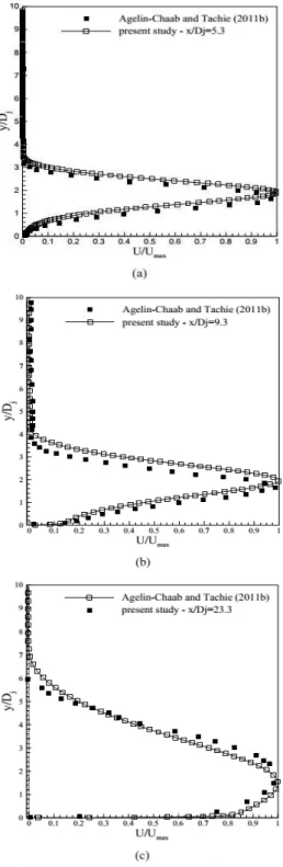
Fig. 8 shows the streamwise velocity profiles at three axial locations where the velocities are normalized by the maximum local streamwise velocity, Umax. Moreover, the wall normal
coordinate y is normalized by the jet diameter, Dj.
The predicted velocity profiles show reasonable agreement with the measurement of Agelin-Chaab and Tachie (2011b). However, the slight difference between computed results and experimental data may be attributed to the difference in turbulent inflow conditions. As previously stated, the background turbulent intensity is much lower than experimental conditions.
Moreover, the lateral velocity profiles at some axial locations are shown in Fig. 9. By using Umax and
Z0.5 as the velocity and length scales, the lateral
velocity profiles at different axial locations collapsed well. A good agreement with experimental data is also observed in Fig. 9.
Fig. 8. Profiles of streamwise velocities at a x/Dj
= 5.3, b x/Dj = 9.3, and c x/Dj = 23.3.
4.2 Comparison between the Characteristics
of Offset Jet Flows Issuing From
the
Square-Shaped and Circular Nozzles
approximately equal in the area of the nozzle and mean exit. Moreover, the inflow velocity profiles are considered uniform in both cases. The Reynolds number based on the mean exit velocity (Uj) and
equivalent nozzle diameter (De) approximately
equals to 8500 for both cases.
Fig. 9. Profiles of streamwise velocity in x-z planes.
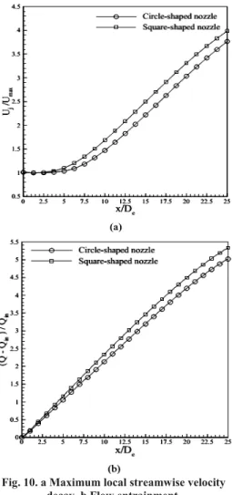
According to Fig. 10a, the decay rate of maximum local velocity of the square-shaped nozzle is greater than the circular one. Moreover, the lengths of potential cores obtained from the computations are equal to 6.78 and 5.35 for circular and square shaped nozzles, respectively, which can be seen in Fig. 10a. Presence of sharp angle on nozzle geometry results in the increasing of mixing rate. Consequently, the decay rate of the streamwise velocity increases, and the length of the potential core decreases. Mi et al. (2000) also demonstrated the identical trend in non-circular free jets. Flow entrainment along the streamwise direction is investigated by evaluating the net mass flux ratio in Fig. 10b, where Qin is the inflow mass flux and Q is
the total mass flux at the location of x in the streamwise direction. The result of Fig. 10b indicates that the flow entrainment from ambient to the square-shaped offset jet is higher than circular one. This can be partly attributed to a higher level of mixing in non circular jets.
As shown in Fig. 11, the jet half width of the square-shaped nozzle is greater than circular nozzle in both the lateral and wall normal directions. As mentioned before, increasing the rate of velocity decay and decreasing the length of potential core both demonstrate the increase of the mixing rate of non circular jets compared to circular ones, which cause the higher flow entrainment. Therefore, the spread of the jet in the wall normal and lateral directions increases.
An important factor to be considered in wall bounded flows is wall shear stress on the adjacent wall. The variation of wall shear stress magnitude on the lower wall along the streamwise direction is shown in Fig. 12. In the case of the square-shaped nozzle, due to the highness of entrainment
compared to the circular case and the same amount of fluid in the recirculation region, the reattachment length decreases. Therefore, the point of maximum wall shear stress on the wall surface shifts to upstream slightly, and its magnitude increases.
Fig. 10. a Maximum local streamwise velocity decay. b Flow entrainment.
4.3 The Influence of Aspect Ratio of
Rectangular Nozzles
In this section, the mean flow fields of offset jets issuing from rectangular nozzles are numerically simulated. All considered cases are approximately equal in the area of the nozzle and mean exit velocity. Moreover, the inflow velocity profiles are considered uniform in all cases. The Reynolds number based on the mean exit velocity (Uj) and
equivalent nozzle diameter (De) approximately
equals to 8500 for both cases. The rectangular nozzles with aspect ratios of 1, 2, 3 and 5 are numerically investigated.
The maximum local velocity decay for considered aspect ratios is shown in Fig. 13a. As the aspect ratio increases, the streamwise velocity decay rate increases in the near field (distances up to 15De).
mixing rate only increases at the near field as a result of an increase in the aspect ratio of the rectangular nozzles. The results of Fig. 13a also show that increasing the aspect ratio of the nozzle results in decreasing the length of potential core. As shown in Fig. 13b, flow entrainment along the streamwise direction for different aspect ratios are approximately the same.
Fig. 11. Jet half width profiles in a the wall normal and b the lateral direction.
Fig. 12. Wall shear stress.
Fig. 13. a Maximum local streamwise velocity decay. b Flow entrainment.
The results of Fig. 14 show that the aspect ratio of a rectangular nozzle only influences the spread rate of the offset jet in the near field (distances up to 15De).
This can be attributed to the difference in decay rate of Umax and the mixing rate in this region. It is also
observed that with an increase in the aspect ratio, due to the higher mixing rate, the spread rate in the wall normal direction increases. As the aspect ratio of the jet increases, the amount of flow entrainment in all considered cases is the same. Therefore, it is expected that with an increase in the spread rate of the jet in the wall- normal direction, the spread rate of the jet decreases in the lateral direction, which can be seen in Fig. 13b.
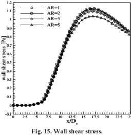
The variation of nondimensional wall shear stress along the streamwise direction for different aspect ratios is shown in Fig. 15. As the aspect ratio increases, the magnitude of maximum shear stress decreases; however, the location of this point remains nearly unchanged.
5. CONCLUSION
turbulent models. Results show that the flow is more affected by the presence of the wall while the jet becomes closer to the adjacent wall. Consequently, low Reynolds turbulent models predict the mean flow field of the 3D offset jet better than high Reynolds turbulent models. Although previous numerical studies stated that the standard k- model is quite appropriate for prediction of 2D offset jets, Results of this study show that for 3D offset jets, the Yang-Shih k- turbulent model is more appropriate than other considered turbulent models.
Fig. 14. Jet half width profiles in the wall normal and b the lateral direction.
Current study also examines how the nozzle geometry can affect the mean flow field of 3D offset jets. Comparison between the flow field of offset jets issuing from circular and square-shaped nozzles demonstrates that the square-shaped offset jet has more efficient mixing with surrounding fluid than the circular offset jet. Therefore, the spread of the offset jet issuing from the square-shaped nozzle increases, in both the wall normal and lateral directions, compared to the circular offset jet. However, maximum shear stress on the adjacent wall in the case of square-shaped nozzle is slightly higher than one in the circular nozzle case.
Fig. 15. Wall shear stress.
Effect of aspect ratio of rectangular nozzles on evolution of the offset jet is investigated. According to the results, it is demonstrated that in the far field region, all considered cases have the same flow characteristics in the range of aspect ratios, which are considered here. However, in the near field region, an increase in the aspect ratio yields an increase in both decay rate of streamwise velocity and spread rate of the jet in the wall-normal direction. Moreover, an increase in the aspect ratio yields a decrease in the spread rate of the jet in the lateral direction. The simulations also show that maximum wall shear stress on the adjacent wall decreases as a result of an increase in the aspect ratio.
REFERENCES
Agelin-Chaab, M. and M. F. Tachie (2011a). Characteristics and structure of turbulent 3d offset jets. International Journal of Heat and Fluid Flow 32(3), 608–620.
Agelin-Chaab, M. and M. F. Tachie (2011b). Characteristics of turbulent three-dimensional offset jets. Journal of Fluids Engineering 133(5).
Ayukawa, K. and T. Shakouchi (1976). Analysis of a jet attaching to an offset parallel plate:1st
report. oscillation of a jet. JSME International Journal Series B 19, 395–401.
Bourque, C. (1967). Reattachment of a two dimensional jet to an adjacent flat plate. In Brown FT (ed) Advances in Fluidics, ASME, New York.
Bourque, C. and G. Newman (1960). Reattachment of a two-dimensional incompressible jet to an adjacent flat plate. Aeronautical Quarterly 11(3), 201–232.
Davis, M. R. and H. Winarto (1980). Jet diffusion from a circular nozzle above a solid plane.
Journal of Fluid Mechanics 101(1), 201–221.
Archive of Applied Mechanics 81(10), 1439– 1453.
Gao, N. and D. Ewing (2007). Experimental investigation of planar offset attaching jets with small offset distances. Experiments In Fluids 42(6), 941–954.
Gao, N. and D. Ewing (2008). On the phase velocities of the motions in an offset attaching planar jet. Journal of Turbulence 9, 1–21.
Goldschmidt, V. W. and P. Bradshaw (1981). Effect of nozzle exit turbulence on the spreading (or widening) rate of plane free jets. In Joint Engineering, Fluid Engineering and Applied Mechanics Conference, ASME, Boulder, Colarado.
Gu, R. (1996). Modeling two-dimensional turbulent offset jets. Journal of Hydraulic Engineering 122(11), 617–624.
Habli, S., H. Mhiri, S. E. Golli, G. Palec and P. Bournot (2001). Numerical study of inflow conditions on an axisymmetric turbulent jet.
International Journal of Thermal Sciences 40(5), 497–511.
Hoch, J. and L. M. Jiji (1981). Two-dimensional turbulent offset jet-boundary interaction. Journal of Fluids Engineering 103, 154–161.
Kumar, A. and M. K. Das (2011). Study of a turbulent dual jet consisting of a wall jet and an offset jet. Journal of Fluids Engineering 133(10).
Launder, A. and D. B. Spalding (1974). The numerical computation of turbulent flows.
Computer Methods in Applied Mechanics and Engineering 3(2), 269–289.
Launder, B. E. and B. I. Sharma (1974). Application of the energy-dissipation model of turbulence to the calculation of flow near a spinning disc. Letters in Heat and Mass Transfer 1(2), 131–137.
Li, Z. W., W. X. Huai and J. Han (2011). Large eddy simulation of the interaction between wall jet and offset jet. Journal of Hydrodynamics 23(5), 544-553.
Lund, T. S. (1986). Augmented thrust and mass flow associated with two-dimensional jet reattachment. AIAA Journal 24(12), 1964–1970.
Mi, J., G. J. Nathan and R. E. Luxton (2000). Centreline mixing characteristics of jets from nine differently shaped nozzles. Experiments In Fluids 28(1), 93–94.
Miozzi, M., F. Lalli and G. P. Romano (2010). Experimental investigation of a free-surface turbulent jet with coanda effect. Experiments In Fluids 49(1), 341–353.
Nasr, A. and J. C. S. Lai (1997). Comparison of flow characteristics in the near field of two parallel plane jets and an offset plane jet. Physics of fluids 9, 2919–2931.
Nasr, A. and J. C. S. Lai (1998). A turbulent plane offset jet with small offset ratio. Experiments In Fluids 24(1), 47–57.
Nasr, A. and J. C. S. Lai (2000). The effects of wall inclination on an inclined offset jet. In 10th International Symposium Applications of Laser Techniques to Fluid Mechanics, Lisbon.
Nozaki, T. (1983). Reattachment flow issuing from a finite width nozzle: Report 4. effects of aspect ratio of the nozzle. Bulletin of JSME 26(221), 1884–1890.
Nozaki, T., K. Hatta and M. Nakashima (1982). Reattachment flow issuing from a finite width nozzle: Report 3. effects of inclinations of reattachment wall. Bulletin of JSME 25(200), 196–203.
Nozaki, T., K. Hatta, M. Nakashima and H. Matsumura (1979). Reattachment flow issuing from a finite width nozzle. Bulletin of JSME 22(165), 340–347.
Nozaki, T., K. Hatta, M. Nakashima and H. Matsumura (1981). Reattachment flow issuing from a finite width nozzle: Report 2. effects of initial turbulence intensity. Bulletin of JSME 24(188), 363–369.
Pelfrey, J. R. R. and J. A. Liburdy (1986a). Effect of curvature on the turbulence of a twodimensional jet. Experiments In Fluids 4(3), 143–149.
Pelfrey, J. R. R. and J. A. Liburdy (1986b). Mean flow characteristics of a turbulent offset jet.
Journal of Fluids Engineering 108, 82–88.
Rajaratnam, N. and K. Subramanya (1968). Plane turbulent reattachment wall jets. Journal of the Hydraulics Division 94, 95–112.
Rajesh Kanna, P. and M. K. Das (2005). Numerical simulation of two-dimensional laminar incompressible offset jet flows. International
Journal of Numerical Methods in Fluids 49(4), 439-464.
Reynolds, W. C. (1987). Fundamentals of turbulence for turbulence modeling and
simulation. Lecture notes for Von Karman
institute Agard Report No. 755.
Sawyer, R. A. (1960). The flow due to a two dimensional jet issuing parallel to a flat plate.
Journal of Fluid Mechanics 9(4), 543–560.
Sawyer, R. A. (1963). Two-dimensional reattaching jet flows including the effects of curvature on entrainment. Journal of Fluid Mechanics 17(4), 481–498.
Shakouchi, T. and S. Kuzuhara (1982). Analysis of a jet attaching to an offset parallel plate: 2nd report. influence of an opposite wall. Bulletin of JSME 25(203), 766–773.
development and validation. Computers and Fluids 24, 227–238.
Song, H. B., S. H. Yoon and D. H. Lee (2000). Flow and heat transfer characteristics of a two-dimensional oblique wall attaching offset jet.
International Journal of Heat and Mass Transfer 43(13), 2395–2404.
Tsunoda, H., Y. Shimizu and T. Kashiwagi (2006). Plane offset jet discharged into water of finite depth. JSME International Journal Series B 49(4), 1111–1117.
Vishnuvardhanarao, E. and M. K. Das (2008). Computation of mean flow and thermal characteristics of incompressible turbulent offset jet flows. Numerical Heat Transfer 53(8), 843– 869.
Vishnuvardhanarao, E. and M. K. Das (2009). Study of the heat transfer characteristics in a
turbulent combined wall and offset jet flows.
International Journal of Thermal Sciences 48, 1949–1959.
Wang, X. K., S. K. Tan and H. Matsumura (2007). Experimental investigation of the interaction between a plane wall jet and a parallel offset jet.
Experiments In Fluids 42(4), 551–562.
Yang, Z. and T. H. Shih (1993). New time scale based k- model for near-wall turbulence. AIAA Journal 31(7), 1191–1198.
Yoon, S. H., K. C. Kim, D. S. Kim and M. K. Chung (1993). Comparative study of a turbulent wall-attaching offset jet and a plane wall jet.
KSME Journal 7(2), 101–112.