Journal Pre-proofs
Bending Performance Evaluation of Aluminium Alloy Tubes Filled with Dif-ferent Cellular Metal Cores
Matej Vesenjak, Isabel Duarte, Joachim Baumeister, Hartmut Göhler, Lovre Krstulović-Opara, Zoran Ren
PII: S0263-8223(19)33726-2
DOI: https://doi.org/10.1016/j.compstruct.2019.111748
Reference: COST 111748
To appear in: Composite Structures
Received Date: 2 October 2019 Revised Date: 25 November 2019 Accepted Date: 27 November 2019
Please cite this article as: Vesenjak, M., Duarte, I., Baumeister, J., Göhler, H., Krstulović-Opara, L., Ren, Z., Bending Performance Evaluation of Aluminium Alloy Tubes Filled with Different Cellular Metal Cores, Composite
Structures (2019), doi: https://doi.org/10.1016/j.compstruct.2019.111748
This is a PDF file of an article that has undergone enhancements after acceptance, such as the addition of a cover page and metadata, and formatting for readability, but it is not yet the definitive version of record. This version will undergo additional copyediting, typesetting and review before it is published in its final form, but we are providing this version to give early visibility of the article. Please note that, during the production process, errors may be discovered which could affect the content, and all legal disclaimers that apply to the journal pertain.
Bending Performance Evaluation of Aluminium Alloy Tubes Filled with Different
Cellular Metal Cores
Matej Vesenjak1, Isabel Duarte2, Joachim Baumeister3, Hartmut Göhler4, Lovre Krstulović-Opara5, Zoran Ren1
1 Faculty of Mechanical Engineering, University of Maribor, Maribor, Slovenia
2 Department of Mechanical Engineering, Centre for Mechanical Technology and Automation, TEMA,
University of Aveiro, Aveiro, Portugal
3 Fraunhofer Institute for Manufacturing Technology and Advanced Materials – IFAM, Bremen, Germany 4 Fraunhofer Institute for Manufacturing Technology and Advanced Materials – IFAM, Dresden, Germany 5 Faculty of Electrical Eng., Mechanical Eng. and Naval Architecture, University of Split, Split, Croatia
Corresponding author: Matej Vesenjak, e-mail: [email protected], phone: +386 2 220 7717
Abstract
A comprehensive bending performance and energy absorption capability of aluminium alloy tubes filled with different cost-effective cellular metal cores were experimentally evaluated for the first time. The following cellular metal cores were evaluated: i) Advanced Pore Morphology (APM) foam, ii) hybrid APM foam and iii) Metallic Hollow Sphere Structures (MHSS). The results have been compared also with the performance of aluminium alloy tubes filled with (ex-situ and
in-situ) closed-cell aluminium alloy foam. The three-point bending tests have been performed at two
loading rates (quasi-static and dynamic) and supported by infrared thermography to evaluate the deformation mechanism, damage progress and failure modes. A thorough heat treatment sensitivity (due to the fabrication procedures of composite structures) study on the aluminium tubes has been performed as well. The results show that a reliable and predictable mechanical behaviour and failure can be achieved with proper combination of tubes and cellular metal core. A low scatter of bending properties and energy absorption capability has been observed. The hybrid APM and the ex-situ foam filled tubes achieved the highest peak load. However, they also exhibit a rapid load drop and abrupt failure once the structure has reached the peak load. The APM, MHSS and in-situ foam filled tubes show more ductile behaviour with a predictable failure mode.
Keywords: cellular metal; foam filled tubes; Advance Pore Morphology (APM) foam; hybrid APM foam; Metallic Hollow Sphere Structure (MHSS); three-point bending; mechanical properties; energy absorption
1. Introduction
The increasing number of vehicles and the current global transport policies addressing the climate changes, have forced the transportation industry to substantially reduce greenhouse gas emissions in the new generation of vehicles [1]. The vehicle weight reduction is a well-known strategy that has been adopted to reduce the harmful emissions and to improve fuel economy [2]. For example, a weight reduction of 100 kg can reduce fuel consumption by 0.3-0.5 litres per 100 km, leading to a reduction in CO2 emissions of about 0.85-1.4 kg per 100 km [3]. At the same time, the manufacturers have found cost-effective solutions to fabricate safer vehicles. To achieve these targets, the lightweight multi-material approach has proven to be very promising in terms of weight saving and preserving economic feasibility [3,4]. It allows the material selection for each part of a vehicle, based on several factors, such as mechanical performance, weight reduction, durability, manufacturability and costs. The utmost appropriate combination of two or more materials is usually made by optimisation methods [5]. Two main concepts are used for this purpose: the first is the weight optimisation concept for weight saving and the second the cost optimisation concept to reduce the overall cost of the process. Several approaches have been developed for material selection and multi-materials design [4,6,7]. These approaches are usually based on two or three materials selection criteria. For example, Ashby’s method [5] defines a material performance index for each material that is a performance to cost ratio. Each material in multi-material design is selected based on its function individually. The traditional high density steel materials have been being replaced by light materials (e.g. advanced steels, aluminium and their alloys) [8]. New lightweight energy absorbing structures with predictable and stable behaviour have been developed and experimentally and numerically tested before incorporation into new generation of vehicles. For example, thin-walled structures filled with lightweight cellular materials (e.g. polymeric foams and metallic foams) have been studied under compressive and bending loads to replace the actual energy absorbers, the empty thin-walled tubes [3,8–10]. Herein, the cellular materials have the function to improve the crashworthiness as well as to reduce the noise and vibrations. The use of such cellular materials does not only foster environmental advantages, but also offers an approach to improve vehicle economics. The latter is affected by increasing fuel costs and by reducing vehicle mass. The cellular materials are usually incorporated as a filler [11–13] or a core [14] into the thin-walled tubes or sandwich panels, using different fabrication methods. Until now, the results have shown that the aluminium alloy closed-cell foams are one of the best cellular materials to use as a filler of empty structural parts, contributing to a reduction of the vehicle weight and simultaneously to improve the crashworthiness of the resulting composite structures. More specifically, results have indicated that the in-situ foam filled tubes [12] made of aluminium alloys, in which the filling of the tube is made during its foam formation, promoting a good metallic bond between the foam and the inner wall of the thin-walled tube, are a pre-requisite for an efficient crash energy absorber. Additionally, the in-situ foam filled tubes deform under compressive and bending loads without formation of cracks. Similar research has been also carried out by using syntactic foams [15–18] as tube fillers [19].
The scope of this research topic is to develop cost-effective energy absorbing lightweight structures with a reliable and predictable mechanical behaviour and failure. Thus cellular metals, such as Advanced Pore Morphology (APM) foam elements, hybrid APM foam elements and Metallic Hollow Sphere Structure (MHSS) were studied as fillers of the thin-walled tubes made
of aluminium alloy in this paper. The APM foam elements coated with polyamide or hybrid APM foam elements coated with expandable epoxy have a wide range of potential applications, e.g., energy absorbing structural elements, stiffening elements (in shell structures), core layers, damping elements, or part of a composite material [20–23]. One of their main advantages is their simple use as a filler element of hollow parts to increase the stiffness and impact energy absorption capability, e.g., a hollow automotive part can be filled with APM foam elements bonded with adhesive. Using the APM foam elements as a filler material is also advantageous since any hollow part shape and geometry can be easily fully filled, which can represent a challenging problem, when using conventional foam materials. On the other hand, the MHSS represent a unique group of porous materials which are being increasingly used in modern engineering applications (e.g. for energy absorption, damping and insulation) [24–28]. The manufacturing procedure assures high uniformity and regularity of hollow spheres (HS) distribution with constant pore size and wall thickness resulting in a very small scattering of their properties [25,26,29]. This is one of their main advantages in comparison to conventional porous structures that exhibit many imperfections (e.g. missing cell walls, variable intercellular wall thicknesses, cracks, irregular topology etc. [30–33]).
The studied light foam-filled structures were tested on a three-point bending testing machine under quasi-static and dynamic loading conditions. The mechanical properties of the analysed structures were compared to the thin-walled tubes filled with aluminium alloy foams prepared by powder metallurgy method [11–13].
2. Fabrication of the specimens
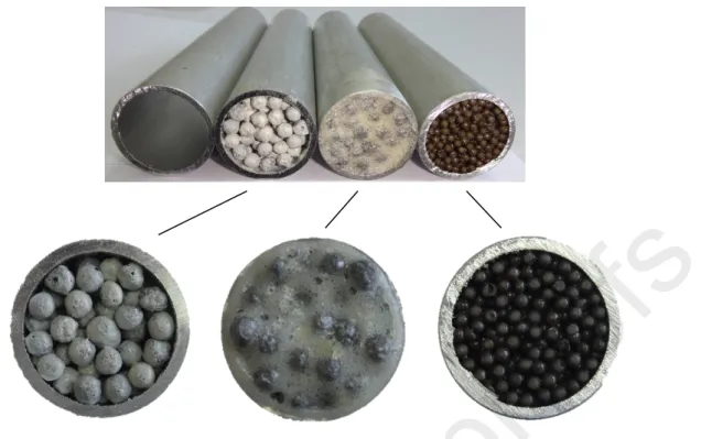
The three-point bending specimens consisted of identical cylindrical aluminium alloy tubes filled with various cellular metals. The tubes were made of aluminium alloy AA 6060 T66 with the outer diameter of 30 mm, inner diameter of 26 mm and length of 150 mm. Within this study, three different cellular materials have been considered as a tube filler (Fig. 1 and Table 1): APM foam elements, hybrid APM foam elements and MHSS, resulting in APM foam filled tubes, hybrid APM foam filled tube and MHSS filled tube. The average bulk densities for APM foam, hybrid APM foam, and MHSS are 0.42 g/cm3 (std. deviation: 0.009 g/cm3), 0.46 g/cm3 (std. deviation: 0.021 g/cm3), 0.35 g/cm3 (std. deviation: 0.006 g/cm3), respectively. Since the filling procedure of the tubes with various cellular cores requires heating, a set of empty tubes (ETs) was also subjected to the same heating procedure in order to accurately evaluate the effective influence of the cellular filler within the tubes on the mechanical properties of composite structures. The tested ETs (with and without heat treatment) are listed in the Table 1.
Figure 1. Analysed specimens (upper line from left to right): empty tube (ET), APM foam filled tube, hybrid APM foam filled tube and MHSS filled tube.
Table 1. Specimens and testing programme overview. Thermal
treatment of the Al tube
Core filler Average core bulk density [g/cm3] Average specimen mass [g] Loading velocity [mm/s] Number of specimens 0.412 4 APM - -108.5 75.5 0.1 2 0.423 4 190 °C (2 h) APM - -109.2 75.3 284 2 0.461 4 hybrid APM - -112.7 75.5 0.1 2 0.460 4 160 °C (3 h) hybrid APM - -112.2 74.5 284 2 0.346 4 MHSS - -102.1 75.9 0.1 2 0.355 4 200 °C (2 h) MHSS - -102.5 76.1 284 2 - 0.1 2 None -- -75.3 75.2 284 2
2.1. Advanced pore morphology (APM) foam filled tubes
The APM foam consists of nearly spherical shaped closed-cell porous structure with integral skin [20,21,34–37]. The manufacturing procedure consists of powder compaction of AlSi10 alloy with
TiH2 foaming agent to obtain expandable precursor material in the shape of wires [34,38,39]. The precursor wires were cut into small granules, which are then expanded into spherical foam elements due to heat reaction of the TiH2 foaming agent in a continuous belt furnace [21,40]. The average size of the APM elements used in this study is approx. 5 mm. From the furnace, the elements are led to a powder bath of polyamide PA 12 powder. The empty aluminium alloy tubes were filled with the coated APM elements [41]. Four empty and eight APM foam filled tubes were then submitted to a heat treatment for bonding, curing the polyamide at 190 °C for 2 h.
2.2. Hybrid advanced pore morphology (APM) foam filled tubes
The fabrication procedure of the hybrid APM foam consists of the same steps as the fabrication of the APM foam elements coated with polyamide, described in previous section. The only difference represents the final step (coating). The 5 mm AlSi10 APM foam elements are coated with the expandable (foamable) epoxy adhesive Araldite AT1-1 containing 1.5 wt% Genitron OB 4,4′-Oxybis (benzene-sulphonyl hydrazide) based foaming agent [23,42], instead of polyamide. The hybrid APM foam elements were inserted into the empty aluminium alloy tubes. Four empty and eight hybrid APM foam filled tubes were then placed into the furnace with 160 °C for 3 h. During the heat treatment process, the epoxy expanded and formed the secondary polymer foam structure between the APM foam elements, resulting in the hybrid APM foam structure.
2.3. Metallic hollow spheres structure (MHSS) filled tubes
The metallic hollow spheres presented in this study were fabricated by the powder metallurgy process [18,24,27,43,44]. Their size is defined by the polymer (e.g. polystyrene) spheres, which are sprayed with metal powder suspended in a binder-water mixture. The coated spheres (also known as green spheres) are then subjected to heat treatment to: i) sinter and harden the metal layer and ii) remove the polystyrene core and the binder by pyrolysis. The result of this process are hollow spheres made of steel (Fe / 0.6%P / 5%Cu) with outer diameter of approx. 2.5 mm and coated with one-component epoxy Araldite AT1-1. The spheres were then poured into the empty aluminium alloy tubes. Finally, four empty and eight MHSS filled tubes were subjected to a heat treatment (bonding) process at 200 °C for 2 h.
3. Experimental methods
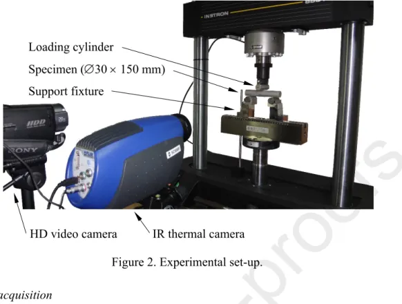
3.1. Three-point bending testsThe quasi-static and dynamic three-point bending tests have been performed using the servo-hydraulic testing machine INSTRON 8801 according to the standard ISO 7438 [45]. The specimens were placed on the flexure fixture 2810-181 (INSTRON part number: A1122-1010) with two cylindrical supports (Ø20 mm with a 100 mm support distance) and bended by the middle cylinder (Ø20 mm), as shown in Fig. 2. The cylindrical supports were fixed by a wire to avoid their rotation during bending tests. The applied relative displacement was approximately 35 mm. The crosshead rates were 0.1 mm/s (quasi-static) and 284 mm/s (dynamic).
IR thermal camera HD video camera
Loading cylinder
Specimen (30 150 mm) Support fixture
Figure 2. Experimental set-up. 3.2. Data acquisition
The displacement of the loading cylinder and reaction force at the support cylinders have been recorded during the loading process for subsequent analysis of the mechanical properties and evaluation of the force-deflection diagrams. The bending tests have been monitored by a high definition video camera (SONY HDR-SR8) in case of the quasi-static loading and an infrared (IR) thermal camera (FLIR SC 5000, frame rate of 158 Hz with 0.02 K sensitive InSb focal point array detector) in case of the dynamic loading. The IR thermography allows for observation of initiation and appearance of cracks and their propagation together with the development of plastification zones and level of plastic deformation on specimen’s surface [46–48].
3.3. Testing plan
Four specimens of each cellular core filler type (APM, hybrid APM and MHSS) per loading velocity have been subjected to bending loading at room temperature. Additionally, four bending tests of empty tubes experiencing same thermal treatment needed for bonding of different cellular core fillers have been conducted, two under quasi-static loading and two under dynamic loading. Furthermore, empty tubes without thermal treatment have been subjected to bending tests as well. The testing plan and number of specimens are summarized in Table 1.
4. Results of tested specimens
4.1. Bending behaviour of APM foam filled tubes
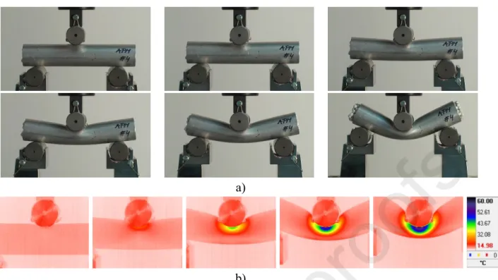
Fig. 3 illustrates the deformation and failure modes of APM foam filled tubes subjected to quasi-static (Fig. 3a) and dynamic (Fig. 3b) three-point bending loading conditions.
a)
b)
Figure 3. Deformation sequence during the three-point bending experiments of the APM foam filled tubes at: a) quasi-static (displacement increment ≈ 6 mm) and b) dynamic (displacement
increment ≈ 8 mm) loading.
From the figures it can be observed that the quasi-static and dynamic deformation and failure modes of APM filled tubes are identical. No cracks were observed in the tension region. However, the filler was pushed out of the tube, indicating a weak bonding between the filler and the tube. The results indicate that the amount of the pushed-out-filler is identical at both ends of the tube. At higher bending loads, these structures develop plastic hinges, allowing large deflection without the failure of the tube. Three main collapse mechanisms were observed during the three-point bending loading process: indentation, buckling and development of plastic hinges.
Figure 4. Load–deflection (left) and energy absorption (right) relationships of the APM foam filled tubes and empty tubes, subjected to the same treatment as filled tubes.
Fig. 4 shows the load-deflection (Fig. 4a) and energy absorption (Fig. 4b) relationships of the APM foam filled tubes and empty tubes (subjected to the same thermal treatment as the filled tubes) under quasi-static and dynamic loading conditions. A negligible strain-rate sensitivity has been observed. The bending response of the tested specimens can be divided into three main regions: (i) the initial linear elastic region, (ii) the slow increase in load up to the maximum (peak) force (also known as ovalisation plateau) and (iii) the slow failure and damage progression region. However, some APM foam filled tubes show a slight increase of the load (or a trend to achieve a plateau like behaviour after reaching peak force) instead of the typical slow failure and degradation (Fig. 4a). Thus, a certain scattering of the properties can be observed after achieving the peak force. This is due to a weak bonding between the APM foam filler and the inner surface of the tube as well as the chemical structure of the polymer used to bond the APM foam elements. The polyamide with a chemical formula CO-NH is formed by long, multiple-unit molecules in which the repeating units in the molecular chain are linked together by amide groups. Such thermoplastic polymers usually exhibit an excellent flexibility at low temperatures. They can be used up to 125 °C of service temperature and are not brittle above −40 °C [49]. Thus, the movement of the filler at the ends of the tube (Fig. 3b) can be attributed to the increase of the temperature in the tensile region (above 30 ºC, Fig. 3b) and the excellent flexibility of the polymer. Results indicate that there is a less efficient load transfer between the tube and the APM foam filler. Nevertheless, all APM foam filled tubes have higher load-carrying capability than the empty tubes (Fig. 4a). The ranges of the peak load (Fig. 4a) are between 9.68 kN and 10.88 kN and between 8.64 kN and 9.64 kN for APM foam filled tubes and empty tubes, respectively. The presence of the filler clearly leads to an increase of the bending resistance, achieving higher energy absorption capability in comparison to empty tubes (Fig. 4b). For 25 mm of the deflection, the ranges of energy absorption (Fig. 4b) are between 210.7 J and 239.7 J and between 191.6 and 211.7 J for the filled structures and empty tubes, respectively. For 30 mm of the deflection, the ranges of energy absorption of the filled structures and empty tubes (Fig. 4b) are between 297.9 and 255.7 J and between 253.9 and 228.9 J, respectively.
4.2. Bending behaviour of hybrid APM foam filled tubes
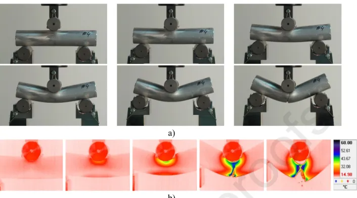
Fig. 5 shows the deformation and failure modes of the hybrid APM foam filled tubes subjected to quasi-static (Fig. 5a) and dynamic (Fig. 5b) three-point bending loading conditions. Results show that the specimens experience an identical deformation and failure mode at quasi-static and dynamic loading conditions. This is more visible from the IR images. Previous results have confirmed that IR thermography is an efficient technique for studying the deformation and failure modes of structures with cellular metal cores through the heat generation [46–48,50]. A single visible crack on the outer tube appears in the tensile region of the specimen, which rapidly propagates, ultimately causing its failure (Fig. 5). The core shear, indentation, buckling and plastic hinges are the main deformation and failure modes of these structures.
a)
b)
Figure 5. Deformation sequence during the three-point bending experiments of the hybrid APM foam filled tubes at: a) quasi-static (displacement increment ≈ 6 mm) and b) dynamic
(displacement increment ≈ 8 mm) loading.
Fig. 6 shows the three-bending load-deflection and energy absorption relationships for the hybrid APM foam filled tubes and the empty tubes. The load-carrying capability and the energy absorption of the hybrid APM foam filled tubes are higher than in empty tubes. The ranges of the peak load (Fig. 6a) are between 14.10 kN and 16.88 kN and between 8.59 kN and 9.22 kN for hybrid APM foam filled tubes and the empty tubes, respectively. For deflection of 25 mm, the ranges of energy absorption of the hybrid APM foam filled tubes and the empty tubes are between 290.2 J and 337.8 J and between 189 J and 201.6 J, respectively (Fig. 6b).
Figure 6. Load–deflection (left) and energy absorption (right) relationships of the hybrid APM foam filled tubes and empty tubes, subjected to the same treatment as filled tubes.
The results demonstrate that the presence of the hybrid APM foam filler improves the crush bending performance of empty tubes (Fig. 4a). However, they show an abrupt failure due to cracking of the tube after reaching the peak load, resulting in lower ductility.
4.3. Bending behaviour of MHSS filled tubes
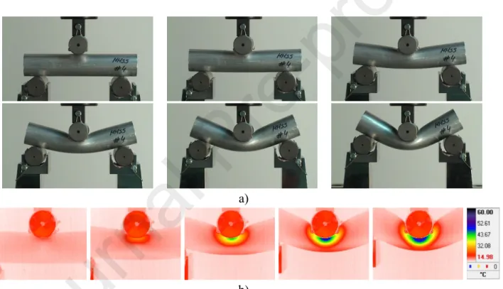
The deformation and failure modes of the MHSS filled tubes subjected to quasi-static and dynamic three-point bending loading conditions are shown in Fig. 7. IR thermography results demonstrate that the MHSS filled tubes have identical deformation and failure modes, independently of the loading velocity (quasi-static and dynamic). No cracks were observed, showing a typical indentation/ovalisation. The MHSS filled tubes exhibit high ductility. Thus, they deform without the formation and propagation of visible cracks and without abrupt failure. The strong bonding combined with a mechanical interlocking between the MHSS filler and the inner tube wall acts as an efficient load transfer from the tube to the foam core. A good interface bonding also contributes to a more axisymmetric deformation.
a)
b)
Figure 7. Deformation sequence during the three-point bending experiments of the MHSS filled tubes at: a) quasi-static (displacement increment ≈ 6 mm) and b) dynamic (displacement
increment ≈ 8 mm) loading.
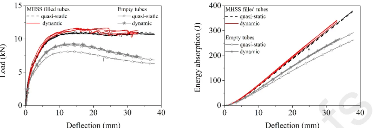
The ranges of the peak load (Fig. 8a) are between 11.62 kN and 10.77 kN and between 8.02 kN and 9.27 kN for MHSS foam filled tubes and empty tubes, respectively. Above the deflection of approx. 12 mm, the MHSS foam filled tubes tend to a load plateau, while the empty tubes start to lose the load-carrying capability. For deflection of 25 mm, the ranges of energy absorption of the hybrid APM foam filled tubes and the empty tubes are between 240.7 J and 252.9 J and between 176.6 J and 200.8 J, respectively (Fig. 8b). The increase in the energy absorption can be attributed to the strong bonding between the filler and the inner tube wall, which acts efficiently in terms of the load transfer.
Figure 8. Load–deflection (left) and energy absorption (right) relationships of the hybrid MHSS filled tubes and empty tubes subjected to the same treatment as filled tubes.
5. Comparison of the bending performance
5.1. Bending behaviour
Fig. 9 shows the comparison of the bending performance of tubes filled with different cellular metals (APM foam, hybrid APM foam and MHSS) analysed in this work with the tubes filled with aluminium alloy closed-cell foams: in-situ (average core bulk density: 0.68 g/cm3, std. deviation: 0.019 g/cm3) [12] and ex-situ (average core bulk density: 0.64 g/cm3, std. deviation: 0.074 g/cm3) [50]. The mechanical results of the in-situ (precursor is placed and foamed inside the tube) and ex-situ (closed-cell foam is inserted into the tube after foaming process) FFTs have previously been reported in [12-46]. It was demonstrated that the in-situ FFTs are an efficient crash energy absorber since they deform under compressive and bending loads without formation of cracks.
Results demonstrate that the hybrid APM foam filled tubes (~14.44 kN, quasi-static; ~15.07 kN, dynamic) and the ex-situ closed-cell foam filled tubes (~11.71 kN, quasi-static; ~17.39 kN, dynamic) achieved the highest values of the peak load in comparison to the APM foam filled tubes (~10.50 kN, quasi-static; ~10.65 kN, dynamic), MHSS filled tubes (~10.89 kN, quasi-static; ~11.49 kN, dynamic) and in-situ foam filled tubes (~10.07 kN, quasi-static; ~10.19 kN, dynamic). The averaged results also demonstrate a minor influence of the loading rate on the load–deflection relationship (positive strain-rate sensitivity). However, the hybrid APM foam filled tubes exhibit a rapid load drop and abrupt failure once the structure has reached the peak load, as it was also observed in case of the ex-situ foam filled tubes (Fig. 9). Both structures fail due to formation of a primary crack in the tensile loaded section of the tube. The crack is initiated in the middle of the filled structures, which corresponds to the maximum tension stress, and rapidly propagates until final failure.
On the contrary, the APM foam filled tubes, MHSS filled tubes and in-situ foam filled tubes show much more stable ductile crushing deformation under bending loads, with a predictable mechanical behaviour. They have a similar load-deflection relationship, which can be defined as a continuous and parabolic increase followed by a gradual trend to plateau during larger deflections. Moreover, they deform without formation and propagation of visible cracks (Fig. 7). However, the MHSS filled tubes (Fig. 7) and the in-situ foam filled tubes [12] show a lower scatter of the properties in comparison to the APM foam filled tubes (Fig. 3), which might correspond to a stronger bonding combined with a mechanical interlocking between the filler and the inner tube wall resulting in a highly efficient load transfer from the tube to the filler.
a) b)
c) d)
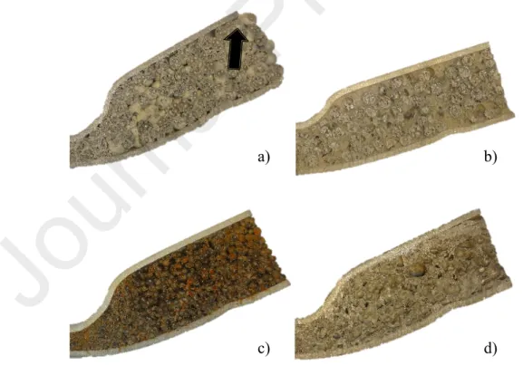
Figure 10. Cross-section of the specimens after being subjected to the bending load: a) APM foam filled tube, b) hybrid APM foam filled tube and c) MHSS filled tube and
Fig. 10 shows the comparison of the internal structure (cross-section) for tubes filled with different cellular cores. A localised area of the core deformation can be observed in the middle of the specimens, which corresponds to the location of the loading cylinder, for all bending specimens. With exemption of APM foam filled tubes, a strong bonding between the cellular core and the inner surface of the tube can be observed. No relative movement between the cellular core and the tube was noted. The core filler has been symmetrically pushed (forced) out of the APM foam filled tubes at both ends due to densification, which also leads to a lower bending performance (peak load).
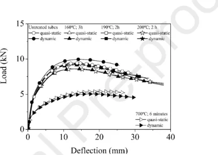
The difference in the crush bending performance is also significantly influenced by thermal treatment of the tubes to which they are subjected during the fabrication of the filled structures. Fig. 11 illustrates the load–deflection relationships under quasi-static and dynamic loading conditions of untreated (as-received) and heat treated empty tubes.
Figure 11. Averaged bending behaviour (load–deflection relationships) of empty tubes subjected to different heat treatments at quasi static and dynamic loading conditions.
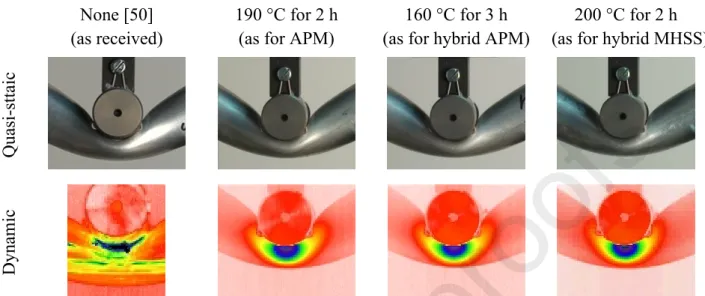
From Fig. 11 it can be observed that the heat treatment (with increasing temperature) significantly lowers the mechanical properties of empty aluminium alloy tubes, which in turn decreases their crush bending performance (especially in the case of the heat treatment at 700 °C). It should be noted that during the foaming process (700 ºC), the outer tube made of aluminium starts to soften (it does not melt), promoting a better metallic bonding. However, the structural changes induced by the heating treatment ensure higher ductility, avoiding the severe stress concentrations that might initiate cracking during bending, which can be also observed from the IR thermography images in Fig. 12. The highly localized higher temperatures (associated with local yielding) in case of the as-received tubes, correspond to a failure at lower deflection. The distribution of the highest temperatures over a larger area is assuring a more ductile behavior for the heat-treated tubes. In overall, the thermal heating cycle of the tubes improves the deformation behavior. The structural changes induced by the heat treatment increase ductility, avoiding the stress concentrations without presence of cracks. For example, the load of the bending curve of the case
comparison to the FFTs made of tubes without heat treatment (ex-situ FFTs), they do not fail abruptly. Nonetheless, these structural changes negatively affect the crushing loads, which are also reflected in the specific energy absorption capacity.
None [50] (as received)
190 °C for 2 h (as for APM)
160 °C for 3 h (as for hybrid APM)
200 °C for 2 h (as for hybrid MHSS)
Quasi-sttaic
Dynamic
Figure 12. Final deformation stages of empty aluminium alloy tubes subjected to different heat treatment.
5.2.Energy absorption capabilities
The energy absorption capability has been evaluated from the energy absorbed by the structure during the bending loading. The energy absorption (Fig. 13, left) was calculated by integrating the area under the experimental load–deflection curve for a given tested specimen.
Figure 13. Averaged energy absorption (left) and specific energy absorption (right) relationships of tubes filled with different cores at quasi static and dynamic loading conditions
(FFTs – foam filled tubes).
In general, a minor strain-rate sensitivity can be also observed in terms of energy absorption. From the Fig. 13 it can be noted that the curves representing the ex-situ and hybrid APM foam filled tubes exhibit the highest inclination and thus have the ability of higher energy absorption. The last part of the loading sequence (above the deflection of 20 mm and 27 mm for the ex-situ and
hybrid APM foam filled tubes, respectively) the progressive slope diminishes due to the failure of the composite structure. The energy absorption of MHHS and APM foam filled tubes is similar, while the energy absorption of the in-situ foam filled tubes experiences slightly lower values due to softening of the tube during the foaming process. The Fig. 13 (right) shows the specific energy absorption, which represent the energy absorption capability per unit weight. When observing the specific energy absorption it can be noted that the difference between the ex-situ and hybrid APM foam filled tubes and the MHHS and APM foam filled tubes becomes smaller, while the higher foam density of the closed-cell foam and the softened tube lower the specific energy absorption capability.
6. Conclusions
The paper describes the bending behaviour of light-weight composite tubes subjected to quasi-static and dynamic loading conditions supported. The aluminium alloy tubes were filled with three different cellular metals: i) Advanced Pore Morphology (APM) foam, ii) hybrid APM foam and iii) Metallic Hollow Sphere Structure (MHSS). The three-point bending performance and energy absorption capacity of composite tubes has been evaluated experimentally and compared between each other and with previously tested ex-situ and ex-situ closed-cell foam filled tubes. The deformation mechanism, damage progress and failure modes have been monitored by high-definition images and infrared thermography. In general, three main collapse mechanisms were observed during the three-point bending loading process: indentation, buckling and development of plastic hinges. Furthermore, the influence of the heat treatment needed for bonding of elements (APM, MHSS) and foaming (in-situ foam filled tubes) on the mechanical properties has been evaluated.
The following conclusion could be drawn:
- The APM filled tubes show identical behaviour at the tested loading rates without formation of any visible cracks. However, the filler was pushed out of the tube, indicating a weak bonding between the filler and the tube.
- Hybrid APM foam filled tubes experience an identical deformation and failure mode at quasi-static and dynamic loading conditions, which includes a single visible crack on the outer tube. The rapid propagation of the crack ultimately causes an abrupt failure of the composite tube structure.
- The deformation and failure modes of the MHSS filled tubes subjected to quasi-static and dynamic show similar deformation and failure modes, independently of the loading velocity. The MHSS filled tubes exhibit high ductility without any visible cracks, showing a typical indentation/ovalisation deformation mechanism due to the strong bonding (core and tube). - The experiments showed that the hybrid APM and the ex-situ foam filled tubes achieved the
highest values of the peak load. However, they exhibit a rapid load drop and abrupt failure once the structure has reached the peak load.
- The APM, MHSS and in-situ foam filled tubes show much more ductile crushing deformation, with a predictable failure. Additionally, a low scatter of bending properties has been observed.
- The energy absorption of composite tubes with different cellular core fillers is comparable, however it is strongly affected by the crack propagation (failure) and thermal treatment (during cellular core preparation) of the tube.
Acknowledgments
Authors acknowledge the financial support from the Slovenian Research Agency (research core funding No. P2-0063). Support of the bilateral project (Slovenia – Croatia) BI-HR/018-19-012 is greatly acknowledged. This work was also supported by the Portuguese Science Foundation (FCT), UID/EMS/00481/2019-FCT and CENTRO-01-0145-FEDER-022083 (Centro 2020 program - Portugal 2020).
References
[1] Fontaras G, Zacharof N-G, Ciuffo B. Fuel consumption and CO2 emissions from passenger cars in Europe – Laboratory versus real-world emissions. Prog Energy Combust Sci 2017;60:97–131. doi:10.1016/J.PECS.2016.12.004.
[2] Goede M, Stehlin M, Rafflenbeul L, Kopp G, Beeh E. Super Light Car—lightweight construction thanks to a multi-material design and function integration. Eur Transp Res Rev 2009;1:5–10. doi:10.1007/s12544-008-0001-2.
[3] Njuguna J. Lightweight composite structures in transport : design, manufacturing, analysis and performance. Woodhead Publishing; 2016.
[4] Sakundarini N, Taha Z, Abdul-Rashid SH, Ghazila RAR. Optimal multi-material selection for lightweight design of automotive body assembly incorporating recyclability. Mater Des 2013;50:846–57. doi:10.1016/J.MATDES.2013.03.085.
[5] Ashby MF. Materials selection in mechanical design. Butterworth-Heinemann; 2011. [6] Kleemann S, Fröhlich T, Türck E, Vietor T. A Methodological Approach Towards
Multi-material Design of Automotive Components. Procedia CIRP 2017;60:68–73. doi:10.1016/J.PROCIR.2017.01.010.
[7] Giaccobi S, Kromm FX, Wargnier H, Danis M. Filtration in materials selection and multi-materials design. Mater Des 2010;31:1842–7. doi:10.1016/J.MATDES.2009.11.005. [8] Lehmhus D. Structural Materials and Processes in Transportation. Weinheim, Germany:
2013. doi:10.1002/9783527649846.
[9] Banhart J. Aluminium foams for lighter vehicles. Int J Veh Des 2005;37:114–25. doi:10.1504/IJVD.2005.006640.
[10] Geyer KE. 3rd Int. Conf. In: Banhart J, Fleck NA, editors. Cell. Met. Met. Foam. Technol., Berlin: MIT-Verlag; 2003, p. 25.
[11] Duarte I, Krstulović-Opara L, Vesenjak M. Characterisation of aluminium alloy tubes filled with aluminium alloy integral-skin foam under axial compressive loads. Compos Struct 2015;121:154–62. doi:10.1016/j.compstruct.2014.11.003.
[12] Duarte I, Vesenjak M, Krstulović-Opara L, Anžel I, Ferreira JMFFJMF. Manufacturing and bending behaviour of in situ foam-filled aluminium alloy tubes. Mater Des 2015;66:532–44. doi:10.1016/j.matdes.2014.04.082.
performance of in-situ foam-filled tubes. Compos Struct 2015;124:128–39. doi:10.1016/j.compstruct.2015.01.014.
[14] Banhart J, Seeliger H-W. Aluminium Foam Sandwich Panels: Manufacture, Metallurgy and Applications. Adv Eng Mater 2008;10:793–802. doi:10.1002/adem.200800091. [15] Gupta N, Ricci W. Comparison of compressive properties of layered syntactic foams
having gradient in microballoon volume fraction and wall thickness. Mater Sci Eng A 2006;427:331–42. doi:10.1016/j.msea.2006.04.078.
[16] Szlancsik A, Katona B, Bobor K, Májlinger K, Orbulov IN. Compressive behaviour of aluminium matrix syntactic foams reinforced by iron hollow spheres. Mater Des 2015;83:230–7. doi:10.1016/j.matdes.2015.06.011.
[17] Pan L, Yang Y, Ahsan MU, Luong DD, Gupta N, Kumar A, et al. Zn-matrix syntactic foams: Effect of heat treatment on microstructure and compressive properties. Mater Sci Eng A 2018;731:413–22. doi:10.1016/j.msea.2018.06.072.
[18] Neville BPP, Rabiei A. Composite metal foams processed through powder metallurgy. Mater Des 2008;29:388–96. doi:10.1016/j.matdes.2007.01.026.
[19] Taherishargh M, Vesenjak M, Belova IV V., Krstulović-Opara L, Murch GEE, Fiedler T. In situ manufacturing and mechanical properties of syntactic foam filled tubes. Mater Des 2016;99:356–68. doi:10.1016/j.matdes.2016.03.077.
[20] Busse M, Rausch G, Stöbener K, Baumeister J. Advanced Pore Morphology (APM) Metal Foams 2007.
[21] Stöbener K, Lehmhus D, Avalle M, Peroni L, Busse M. Aluminum foam-polymer hybrid structures (APM aluminum foam) in compression testing. Int J Solids Struct 2008;45:5627–41.
[22] Lehmhus D, Baumeister J, Stutz L, Schneider E, Stöbener K, Avalle M, et al. Mechanical Characterization of Particulate Aluminum Foams—Strain-Rate, Density and Matrix Alloy versus Adhesive Effects. Adv Eng Mater 2010;12:596–603. doi:10.1002/adem.200900315. [23] Baumeister J, Weise J, Hirtz E, Höhne K, Hohe J. Applications of aluminium hybrid foam
sandwiches in battery housings for electric vehicles. Materwiss Werksttech 2014;45:1099– 107. doi:10.1002/mawe.201400358.
[24] Andersen O, Waag U, Schneider L, Stephani G, Kieback B. Novel Metallic Hollow Sphere Structures. Adv Eng Mater 2000;2:192–5.
[25] Banhart J. Manufacture, characterisation and application of cellular metals and metal foams. Prog Mater Sci 2001;46:559–632. doi:10.1016/S0079-6425(00)00002-5.
[26] Smith BH, Szyniszewski S, Hajjar JF, Schafer BW, Arwade SR. Steel foam for structures: A review of applications, manufacturing and material properties. J Constr Steel Res 2012;71:1–10. doi:10.1016/j.jcsr.2011.10.028.
[27] Metallic hollow spheres — materials for the future. Met Powder Rep 2000;55:29–33. doi:10.1016/S0026-0657(00)87339-7.
[28] Öchsner A, Augustin C. Multifunctional Metallic Hollow Sphere Structures. Springer Berlin Heidelberg; 2009. doi:10.1007/978-3-642-00491-9_1.
[29] Ashby MF, Evans A, Fleck NA, Gibson LJ, Hutchinson JW, Wadley HNG. Metal foams: a design guide. Burlington, Massachusetts: Elsevier Science; 2000.
82. doi:10.1016/j.msea.2014.08.002.
[31] Ramamurty U, Paul A. Variability in mechanical properties of a metal foam. Acta Mater 2004;52:869–76. doi:10.1016/j.actamat.2003.10.021.
[32] Duarte I, Banhart J. A study of aluminium foam formation—kinetics and microstructure. Acta Mater 2000;48:2349–62.
[33] Ulbin M, Vesenjak M, Borovinšek M, Duarte I, Higa Y, Shimojima K, et al. Detailed Analysis of Closed-Cell Aluminum Alloy Foam Internal Structure Changes during Compressive Deformation. Adv Eng Mater 2018. doi:10.1002/adem.201800164.
[34] Stöbener K. Advanced Pore Morphology (APM) - Aluminiumschaum. University of Bremen, 2007.
[35] Stöbener K, Baumeister J, Rausch G, Rausch M. Forming metal foams by simpler methods
for cheaper solutions. Met Powder Rep 2005;60:12–6.
doi:http://dx.doi.org/10.1016/S0026-0657(05)00316-4.
[36] Vesenjak M, Borovinšek M, Fiedler T, Higa Y, Ren Z. Structural characterisation of advanced pore morphology (APM) foam elements. Mater Lett 2013;110:201–3. doi:10.1016/j.matlet.2013.08.026.
[37] Ulbin M, Borovinšek M, Higa Y, Shimojima K, Vesenjak M, Ren Z. Internal structure characterization of AlSi7 and AlSi10 advanced pore morphology (APM) foam elements. Mater Lett 2014;136:416–9. doi:10.1016/j.matlet.2014.08.056.
[38] Baumgärtner F, Duarte I, Banhart J. Industrialization of Powder Compact Toaming Process. Adv Eng Mater 2000;2:168–74. doi:10.1002/(sici)1527-2648(200004)2:4<168::aid-adem168>3.0.co;2-o.
[39] Stöbener K, Rausch G. Aluminium foam–polymer composites: processing and characteristics. J Mater Sci 2009;44:1506–11.
[40] Duarte I, Ferreira JMF. 2D Quantitative Analysis of Metal Foaming Kinetics by Hot-Stage Microscopy. Adv Eng Mater 2014;16:33–9. doi:10.1002/adem.201300171.
[41] Duarte I, Vesenjak M, Krstulović-Opara L, Ren Z. Compressive performance evaluation of APM (Advanced Pore Morphology) foam filled tubes. Compos Struct 2015;134:409– 20. doi:10.1016/j.compstruct.2015.08.097.
[42] Baumeister J, Monno M, Goletti M, Mussi V, Weise J. Dynamic Behavior of Hybrid APM (Advanced Pore Morphology Foam) and Aluminum Foam Filled Structures. Metals (Basel) 2012;2:211–8. doi:10.3390/met2020211.
[43] Augustin C, Hungerbach W. Production of hollow spheres (HS) and hollow sphere structures (HSS). Mater Lett 2009;63:1109–12. doi:10.1016/j.matlet.2009.01.015.
[44] Behnam M, Salemi Golezani A, Mehdizadeh Lima M. Optimization of surface quality and shell porosity in low carbon steel hollow spheres produced by powder metallurgy. Powder Technol 2013;235:1025–9. doi:10.1016/j.powtec.2012.11.038.
[45] ISO 7438. ISO 7438: 2005 - Metallic materials-bend test. ISO International Organization for Standardization; 2005 2005.
[46] Bagavathiappan S, Lahiri BB, Saravanan T, Philip J, Jayakumar T. Infrared thermography for condition monitoring – A review. Infrared Phys Technol 2013;60:35–55. doi:http://dx.doi.org/10.1016/j.infrared.2013.03.006.
[47] Pastor ML, Balandraud X, Grédiac M, Robert JL. Applying infrared thermography to study the heating of 2024-T3 aluminium specimens under fatigue loading. Infrared Phys Technol
2008;51:505–15. doi:http://dx.doi.org/10.1016/j.infrared.2008.01.001.
[48] Krstulović-Opara L, Surjak M, Vesenjak M, Tonković Z, Kodvanj J, Domazet Ž. Comparison of infrared and 3D digital image correlation techniques applied for mechanical testing of materials. Infrared Phys Technol 2015;73:166–74. doi:10.1016/j.infrared.2015.09.014.
[49] Fabris HJ, Knauss WG. Synthetic Polymer Adhesives. Compr Polym Sci Suppl 1989:131– 77. doi:10.1016/B978-0-08-096701-1.00208-1.
[50] Duarte I, Vesenjak M, Krstulović-Opara L. Dynamic and quasi-static bending behaviour of thin-walled aluminium tubes filled with aluminium foam. Compos Struct 2014;109. doi:10.1016/j.compstruct.2013.10.040.