Abstract
A series of dynamic tests were conducted on a closed-cell alumi-num alloy foams in order to determine experimental failure surface under impact loading conditions. Quasi-static tests have also been performed to investigate failure mechanism under different stress paths. Three typical types of deformation modes can be observed, which corresponds to the different failure mechanism. The failure loci of the foam in principal stress plane are explored from quasi-static to dynamic loading conditions. A significant strength en-hancement is identified experimentally. The expansion of the failure locus from the quasi-static to the dynamic test is almost isotropic. A modified failure criterion for the metallic foam is proposed to predict failure locus as a function of strain rate. This rate-dependence failure criterion is capable of giving a good de-scription of the biaxial failure stresses over a wide range of the strain rates.
Keywords: Metallic Foams; Impact loading; Failure mode; Dynamic failure surface
Impact Response of Aluminium Alloy
Foams Under Complex Stress States
1 INTRODUCTION
Sandwich structures are widely used in various engineering applications such as protective struc-tures of autos and aircrafts, due to their excellent energy absorption capability, high specific strength and superior shock-resistance characteristics under such extreme loading as blast or ballis-tic impact (Ashby et al, 2000; Lu and Yu, 2003; Gibson and Ashby, 1997; Djamaluddin et al, 2015).
Zhiwei Zhou a, b Buyun Su a Zhihua Wang a Xuefeng Shu a,* Longmao Zhao a
a Institute of Applied Mechanics and
Biomedical Engineering, Taiyuan Univer-sity of Technology, Taiyuan 030024, Chi-na
b State Key Laboratory of Frozen Soil
Engineering, Cold and Arid Regions Envi-ronmental and Engineering Research Institute, Chinese Academy of Sciences, Lanzhou 730000, China
*Corresponding author:
http://dx.doi.org/10.1590/1679-78252344
Metallic foams as well as the other cellular materials are used increasingly in engineering applica-tions such as energy absorbers and the cores of sandwich panels due to superior properties like high specific strength, high specific stiffness and high energy dissipation capacity. In these applications, metallic foams may be subjected to multiaxial loadings. The deformation modes and the macroscop-ic stress distributions are non-uniform under combined stress states. Therefore, it is necessary to develop an understanding of mechanical properties for metallic alloy foams under multiaxial stress states. The goal of the present study is to model accurately the mechanical behavior of the alumi-num alloy foam under different stress paths, especially multiaxial impact loading conditions.
Many previous works have been performed to investigate the multiaxial behavior of commer-ly available foams ranged from pocommer-lymer-based foams to metal-based foams. Gibson et al. (1989) experimentally studied several failure mechanisms such as elastic buckling, plastic collapse and brit-tle fracture for cellular solids under multiaxial loading conditions, and further suggested a failure criterion for ideal cellular solids. Deshpande and Fleck (2000a) investigated experimentally the fail-ure behavior of aluminum alloy foams under a range of axisymmetric compressive and hydrostatic stress states. Two phenomenological constitutive models were proposed to characterize multiaxial failure behavior of the metallic foams. In addition, a series of axisymmetric compressive and tensile tests on the polymer foams have been performed in order to further verify two constitutive models (Deshpande and Fleck, 2001). Gioux et al. (2000) carried out experimental works on both closed-cell aluminum alloy foams (Alporas) and open-cell aluminum alloy foams (Duocel) under axisymmetric triaxial and biaxial loading condition to verify various published theoretical failure criteria. Doyoyo and Wierzbicki (2003) modified the standard Arcan apparatus (Arcan et al., 1978) for investigating experimentally biaxial response of ductile and brittle aluminum foams. A phenomenological failure criterion is presented to predict the measured failure surfaces for Alporas and Hydro closed-cell uminium foams. Ruan et al. (2007) employed a custom-built triaxial testing apparatus to investi-gate the effect of strain rate in the experimental failure surface of CYMAT closed-cell aluminum foams. Recently, Combaz et al. (2010a, 2011) used a triaxial testing device to perform a series of multiaxial experiments on replicated aluminum foam. They proposed that the shape of the meas-ured failure surface for the replicated aluminum foams depended on the third stress tensor invariant.
The aforementioned literatures related to the multiaxial behavior of the foams have been fo-cused on quasi-static failure surface and failure criterion. The deformation modes and failure mech-anism under different combined stress states, which is closely related to constitutive property of the foams, have not been experimentally investigated as yet. Hence, this paper presents dynamic and quasi-static biaxial tests for a closed-cell aluminum alloy foam with two objectives in mind. The
Doyoyo and Mohr., 2006; Yu et al., 2006; Peroni et al., 2008; Peroni et al., 2012; Zhou et al., 2012a, 2012b, 2014; Hangai et al., 2013; Pichler and Lackner, R.,Duarte et al., 2014; Kaya and Fleck, 2014; Li et al., 2014; Alvandi-Tabrizi et al., 2015; Storm et al., 2015; Vesenjak et al., 2016). But experi-mental investigations of metallic foams under dynamic multiaxial loading condition are not availa-ble by now. The main reason for such situations lies in the difficulties to carry out dynamic multi-axial experiments because of the requirements for both a feasible multimulti-axial design in a tiny limited space and an accurate data measurement under impact conditions. Therefore, the second goal of this paper is to investigate experimentally biaxial mechanical behavior of the metallic foams under impact conditions, and to further determine the dynamic failure surface of the metallic foams. on the dynamic results, a rate-dependence failure criterion is proposed to predict the failure surface as a function of strain rate for the foam. Moreover, the size effect and the anisotropic behavior for the closed-cell aluminum alloy foam were also experimentally investigated in this paper.
2 MATERIALS AND TESTING PROCEDURES
2.1 Materials and Samples
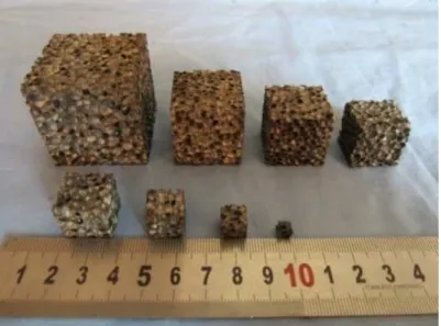
The material under investigation is the closed-cell aluminum alloy foam manufactured by the China Shipbuilding Industry Corporation (CSIC). A typical electron microscope photograph of this foam microstructure is shown in Figure 1. The manufacturers’ data shows that the chemical composition of the matrix materials (cell wall) is AL–0.45 wt.%Mg–0.52 wt.%Ca–0.21 wt.%Ni. It has a nominal density of 2710 kg/m3, Young’s modulus of 70.2 GPa and yield strength of 192 MPa. The density of this aluminum alloy foam is 0.405g/cm3, corresponding to the mean relative density of 15%, which is defined as the density of the foam blocks divided by the density of the cell-wall material. It is worth emphasizing that the relative density of the foam samples used in tests has variation value of ±0.8% relative to the mean value. The main reason such situation is the variation of cell diameter. The cell diameter of the closed-cell foam has a range of value from 1 mm to 4.5 mm, corresponding to the mean diameters of 2.4 mm. In this paper, all foam samples were fabricated with high preci-sion to minimize damage of the local cell wall. Electrical Discharge Machining method (EMD) was adopted to obtain the foam samples. All foam samples were cut from rectangular foam blocks with dimension of 1500 mm ×500 mm ×100 mm supplied by the manufacturers.
2.2 Sample Sizes
Previous researches reveal that commercial metal foams generally exhibit anisotropic mechanical properties (Gibson and Ashby, 1997; Andrews et al., 1999; Chen et al., 2001; Alkhader and Vureal, 2009; Combaz et al., 2010b; Marie and David, 2013). Thus, uniaxial compression tests are first con-ducted on cubic sample with the dimension of 40mm in three mutually perpendicular principal di-rections (shown in Figure 2) in order to characterize directional properties of this foam, which should be taken into consideration before investigating mechanical behavior. On the other hands, it is well-known that mechanical behavior of metallic foam is strongly sensitive to the ratio of the sample size to the cell size at length scales where the two are of the same order of magnitude (Bast-awros et al., 2000; Onck et al., 2001; Andrews et al., 2001; Jeon and Asahina, 2005; Joseph et al., 2005; Rakow and Waas,2005; Tekoğlu and Onck, 2008; Caner and Bazant, 2009; Jeon et al., 2009; Tekoğlu et al., 2011; Su et al., 2014). Most researchers have adopted big size samples in the me-chanical tests to avoid the size effect of cellular materials (McCullough et al., 1999; Ruan et al., 2002; Saha et al., 2005; Amsterdam et al., 2008; Lu et al., 2008; Shen et al., 2010; Mangipudi and Onck, 2011; Luong et al., 2013; Jin et al., 2015). Thus, In order to ensure the accuracy of the exper-imental results in this paper, size effect of this foam in mechanical behavior was experexper-imentally studied first. The uniaxial compression tests were carried out on cubic foam samples with different dimensions by using Instron testing machine (Model 5544, Instron,) with a 2 kN load cell. The di-mensions of the sample include 5 mm, 9 mm, 13 mm, 17 mm, 21 mm, 25 mm, 30 mm and 40 mm, respectively. The foam samples were carefully prepared using an arrangement, as showed in Figure 3. The uniaxial compression tests were conducted by controlling the constant vertical displacement rate of 0.02mm/s, corresponding to a nominal strain rate of 5.0 × 10⁻⁴s-1. In the previous works, the ratio of samples size to cell size L/d was introduced to analyse the size effect in the mechanical be-havior of metallic foam (Onck et al., 2001; Tekoğlu et al., 2011;). For the sake of illustration con-venience, the ratio of the sample length to cell size of L/d is also used in subsequent analysis.
z
x
y
Loading direction (y axis)
Rectangular foam blocks Cubic sample Loading direction (z axis)
Loading direction (x axis)
Figure 3: Foam samples with different dimensions
2.3 Dynamic Multiaxial Loading Device and Testing Procedures
The Split-Hopkinson pressure bar is nowadays a popular impact loading setup for studying the dy-namic compressive behavior of materials. Initially developed for metallic material testing, it has now been used for many different materials such as polymer materials, geotechnical materials and bio-ical material. A typbio-ical Split-Hopkinson pressure bar device consists of long input and output bars with a short sample placed between them. A projectile launched by a gas gun strikes the free end of the input bar and creates a compressive longitudinal incident wave εi(t). Once this wave arrives at
the bar-sample interface, part of it εr(t), is reflected, whereas the other part passes through the
sample and transforms into the transmitted wave εt(t) in the output bar. Two gauges are fixed at
the middles of input and output bars to collect those experimental data (incident, reflected and transmitted waves) which should be adopted to deduced the forces and the velocities at both faces of the sample and further determinate dynamic constitutive behavior of testing materials.
Teflon sleeve Foam sample
Input and output bar
Beveled bars
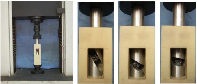
Figure 4: Dynamic multiaxial loading tests.
In order to realize multiaxial dynamic loading, two short cylindrical bars with one bevel end are inserted at the interfaces of the samples and impact-bars, as illustrated in Figure 4. The two short cylindrical bars have the same diameter of 37mm as the input and output bars. The Hopkinson bars and the two short beveled bars are both made of the pure aluminium. The main purpose for this design is to ensure that the incident wave transmits from the input bar to the input beveled bar are not reflected significantly, and the transmitted wave can also propagate from the out-put beveled bar to the output bar completely. The foam sample is inserted at the two parallel bevels instead of contacting with the input and output bars directly and perpendicularly. A square sleeve made of Teflon is applied to support the multiaxial dynamic loading device, and further make sure the only horizontal movement of the beveled bars in whole loading process. It should be pointed out that the friction coefficient between the foam sample and the beveled bars should be large enough to insure that no slippage occurs during multiaxial loading process. In this way, when the foam sample is loaded by multiaxial dynamic loading device, a multiaxial stress state is realized. A series of multi-axial tests on the aluminum alloy foam were performed at the impact velocity of about 10 m/s with the loading angles ranging from 0º (corresponding to the uniaxial compression for a strain rate of 1100s-1) to 60º.
input and output bars. Moreover, these collected strain signals are not only known at the points of strain gauges, but at any point on the input and output bars. Thus, forces and velocities at the interfaces of the bar/samples can be deduced by the local strain signals shifted from the recording points. The associated forces and particle velocities at the interfaces of the bar/samples are then calculated as follows:
( )
( ( )
( ))
input b i r
F
t
S E
t
t
(1)( )
( )
ouput b t
F
t
S E
t
(2)0
( )
( ( )
( ))
input i r
V
t
C E
t
t
(3)0
( )
( )
ouput t
V
t
C
t
(4)Where Finput, Foutput, Vinput and Voutput are forces and particle velocities on bar/samples faces. Sb, E
and C0 are respectively the cross section area, elastic modulus of the bars and the longitudinal wave speed. Εi(t), εr(t), εt(t) are the recorded strain signals collected from the points of strain gauges on
the input and output bars.
Since a stress/strain homogeneous field assumption is not really applicable in this multiaxial loading case of the foam sample with localized deformation mechanism, The mean pressure P(t) as function of the overall crush D(t) is introduced to gives an overall prediction of the multiaxial be-havior of this closed-cell aluminum alloy foam under impact loadings. Based on above deductions of the forces and velocities, the mean pressure P(t) and the overall crush, D(t) (with the same defini-tion as in the quasi-static case) are calculated as follows:
( )
input( ) /
sP t
F
t
S
(5)0
( ) t( ouput( ) input( ))
D t
V T V t dT (6)Where
S
s is the area of the sample face contacting to the beveled bars.2.4 Quasi-static Multiaxial Loading Tests
Figure 5: Quasi-static multiaxial loading tests.
Fr
xy
x
x
X
xy
y
y
FV
Figure 6: Multiaxial stress state of foam sample.
S
L
U
x
(0,y)=0
Uy
(0,y)=0
y
x
U
x
(L,y)=
s
x
U
y
(L,y)=
s
y
L
S
The main goal of quasi-static multiaxial tests is to investigate the multiaxial deformation mode and failure mechanisms, and to further determine the quasi-static failure surface of the foam. There-fore, the stress states of the foam sample in testing process will be analyzed in detail. As the stiff-ness of the cylindrical bars with one bevel is much higher than the stiffstiff-ness of the foam sample, the cylindrical bars are assumed to be rigid in the subsequent analysis. The mean shear stress and the mean normal stress of the foam sample are defined in a local coordinate system, where the x-axis is perpendicular and the y-axis is parallel to the interfaces of the bar/samples (Figure 6). The force along the positive axis of the universal testing machine is defined as the vertical force
F
v. The forceperpendicular to the vertical one is referred to as the horizontal force
F
r, which is the constraining force exerted on the cylindrical bars by the sleeve. For the sake of illustration convenience, the an-gle between the loading direction (vertical direction) of the universal testing machine and the axial direction of the foam sample is referred to as the loading angle, as shown in Figure 6. Clearly, the larger the loading angle is, the more dominant the shear component is. When
0
, the uniaxial tests is achieved. According to the global static equilibrium, the vertical force and the constraining force in the cylindrical bars can be given by following expressions:2 2
sin
cos
v xy x
F
L
L
(7)2 2
cos
sin
r xy x
F
L
L
(8)Where
L
is the length of cubic sample. Based on above analysis, a uniform displacement field (s
x,s
y) at the top interfaces of the foam sample can be defined as to be displacement boundary conditions, as shown in Figure 7.cos
xs
s
(9)sin
ys
s
(10)The proportional loading path is determined by the multiaxial loading angle.
tan
yx
s
s
(11)The kinematically admissible displacement field of the foam sample in whole loading process can be obtained:
( , )
yx
s
u x y
x
L
(12)( , )
yy
s
u x y
x
L
Since small deformations of the foam sample in elastic stage, the strain in the local x-direction, x, the strain in the local y-direction, y, and the shear distortion,
xy can be calculated as follows:( , )
x xx
u
s
x y
x
L
(14)( , )
y0
y
u
x y
y
(15)( , ) x y y
xy
u S
u x y
y x L
(16)
The isotropic material law that establishes the stress-strain relationship under plane-stress con-ditions is introduced in this multiaxial loading state:
2 2 2 2 0 1 1 0 1 1
0 0 0
x x y x xy xy E E E E (17)
In Eq. (17),
C
ij denotes the stiffness matrix of an isotropic lamina in plane stress conditions.
is the Poisson’s ratio of the foams,E
is the Young’s modulus. Eq. (17) can be used to relate the strain and stress ratios as:2
(1
)
x x
xy xy
(18)According to Eq. (7) to (18), the shear stress and compressive stress of the foam sample in the elastic phase (as shown in Figure 6) can be expressed in following equations:
2 22 cos
1
cos
1
V x
F
L
(19)
2 21
sin
1
sin
2 cos
V xy
F
L
(20)y x
Figure 8: Uniaxial compressive stress–stain curves for different loading directions.
3 RESULTS AND DISCUSSIONS
3.1 Isotropic Behavior of the Foams
All macroscopic stress-strain curves in uniaxial compression tests are based on the engineering stress and strain definition. The stress versus strain responses on the cubic samples with dimension of 40mm are shown in Figure 8. The shape of the stress-strain curves is typical of metallic foams, in-cluding an increase up to a peak stress, then a drop to a stage of more or less constant stress, finally an increase rapid to a densification stage. The stress-strain curves obtained from different loading directions are consistent well. In other words, this aluminum alloy foams exhibit obviously isotropic properties.
3.2 Determination of the Sample Dimension
0
( )
(
)
( )
aa
c a
c
d
(22)Densification strain
Dis the strain value corresponding to the stationary point in the efficiency– strain curve where the efficiency is a global maximum, i.e.( )
0
a
d
d
(23)The plateau stress
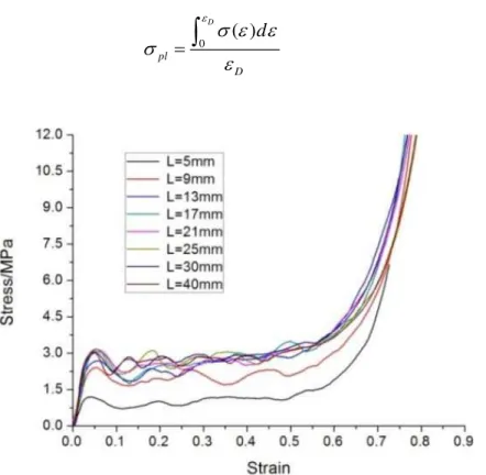
pl, can then be calculated by0
( )
D
pl
D
d
(24)Figure 9: Uniaxial compressive stress–stain curves for foam samples with different sizes.
Figure 10: Stress–strain curve and energy absorption efficiency–strain curve of the foam.
The initial failure stress and the plateau stress are plotted against the foam sample size
L
rela-tive to the cell sized
, as shown in Figure 11. The initial failure stress increases with increasing normalized sample size up to a plateau level atL d
/
7.08
. This testing result closely agrees with the conclusions of Andrews et al. (2001) in terms of the increasing initial failure stress with increas-ingL d
/
6
for the closed-cell foam. The difference is that the growth rate is somewhat faster for this foam. The plateau stress follows a similar pattern, increasing withL d
/
up to a plateau level atL d
/
7.08
. Therefore, it can be clearly concluded that in order to obtain the bulk mechanical properties of this aluminum alloy foam, a block of sizesL d
/
6
is necessary. Thus, the cubic sample with the dimension of 17mm is adopted in the multiaxial tests.3.3 Multiaxial Behavior of the Foam During Quasi-static Tests.
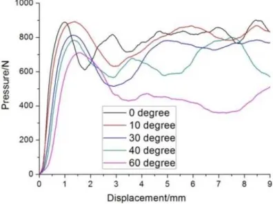
The quasi-static pressure-displacement curves of the foams at different loading angles are summa-rized in Figure 12. For these multiaxial results, the following observation can be made: In the region, the vertical pressure versus displacement curve is initially linear, but becomes non-linear at the following short stages due to the loss of stiffness caused by the progressive crushing of cells. behavior continues until the peak pressure is achieved, after which the load drops. The slope of the curve and the initial peak pressure decreases with the increase of loading angle
, which represents that the stiffness and strength mechanism is strongly sensitive to the stress path (loading angle).Figure 12:Vertical pressure-displacement curves for different loading angles.
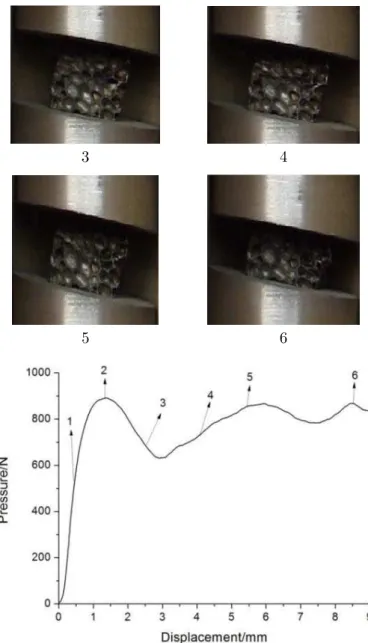
In an effort to show how crushing evolved through the entire process of loading, the defor-mation process of the sample corresponding to points on the curves were captured by camera under the different loading angles. For the cases of small loading angles such as
10
, the whole crushing process of the foam is similar to the results observed in uniaxial compression due to the stress state dominated by compressive stress. First, the peak pressure represents the initial plastic buckling of the weakest layer in the foams. Subsequently, deformation will be localized within this layer until these cells were fully compacted and the next series of cells starts to collapse (as shown in Figure 13).3 4
5 6
Figure 13: Images for deformation process and the associated pressure history for foam sample.
1 2
3 4
5 6
Figure 15: Side view of foam sample.
It is clearly seen that there is no obvious crushing area except for a fracture band across the whole sample. The main reason for this fracture is that shear stress plays important role in defor-mation mode. In other words, as that the shear displacement is more than the normal displacement under this proportional path, the failure mode of the sample in the cases of large loading angles is dominated by shear stress.
For the cases of loading angle
40
, the cell area in the top surface of the sample initially started to plastic collapse, as shown in Figure 16. The deformation process of localized crushed bands from the initial plastic collapse area to the side of the sample, rather than across the whole sample, is observed. Finally, a single crack band further formed along the initial crush bands, and meanwhile the cell layer near the top surface of the sample is successive crushed. It means that two deformation modes competitively exist in the post-peak stage due to the shear stress. Furthermore, the shear stress and the normal stress both play a fairly role in deformation process under this stress path. It is worthwhile to emphasize that the deformation processes captured by images reveal no obvious slippage between the sample and the bevels at the elastic stage for all loading angles. As evidenced by the global images from Figures 13 to 16, that is to say the analysis for the displace-ment boundary (shown in section 2.4) is reliable at the elastic stage.3 4
5 6
Figure 16: Images for deformation process and the associated pressure history for foam sample.
3.4 Multiaxial Behavior of the Foam During Dynamic Tests
Fi-nally, as observed from the plateau level of each curve, the quasi-static curves are all lower than the corresponding dynamic ones, which indicated a significant effect of the strain rate.
Figure 17: Dynamic pressure-displacement curves for different loading angles.
For quantitatively illuminating the enhancement from quasi-static to dynamic results, the ini-tial peak pressure and the plateau pressure will be analyzed in following section. The plateau pres-sure is defined as follows:
max
0
max
( )
spl
p D dD
p
s
(25)Where
s
max is the maximum displacement of the corresponding crushing duration. The peak pres-sure and the plateau prespres-sure at different loading angles for dynamic and quasi-static cases are plot-ted in Figure 18. It is evident that the peak pressure and the plateau pressure of the foams under dynamic conditions is significantly higher than the results under quasi-static conditions. A notable strength enhancement is concluded from the dynamic to the quasi-static results.3.5 Determination of Dynamic Failure Surface
Many works have been performed to study the rate effect in the mechanical behavior of the metallic foams, such as the uniaxial failure stress, the plateau stress, the densification behavior and the en-ergy absorption capacity (Zhao,1997; Deshpande and Fleck, 2000b; Demiray et al., 2006; Yu et al., 2006; Zhou et al., 2012a, 2012b, 2014; Castroa et al., 2013; Alia et al., 2014; Goel et al., 2014; Li et al., 2014; Wang et al., 2014; Kishimoto et al., 2014; Caprino et al., 2015; Storm et al., 2015; Su et al., 2015). Nevertheless, little literature has involved the experimental failure surface, especially the dynamic failure surface which is very important for the engineering applications of the metallic foams. Therefore, the multiaxial failure stresses obtained from quasi-static to dynamic tests are plotted in principal stress plane in order to probe the failure surface of the aluminum alloy foams over a wide range of the strain rates, as shown in Figure 19. It is clearly found that the significant expansion of experimental failure locus from low to high strain rates is almost isotropic, even though the normal stress/shear stress ratio for a given loading angle is same under quasi-static and dynamic loading conditions.
Generally speaking, the mechanisms of rate sensitivity of the metallic foams may be attributed to the effects of intrinsic length scale of the material, the rate sensitivity of base material, the com-pression and flow of gas in cells, micro-structural morphology including the form, shape, size of the individual cell and other effects such as inertia effect, which may cause to different deformation modes of the material at high strain rate cases. On the other hand, the mechanical properties of commercial metallic foams usually have variations of ±5% from the mean value as highly heteroge-neity of materials. Based on aforementioned considerations, we adopt the criterion of a 20% increase in failure stress to define the strain rate sensitivity. It is consistent with the fact that the metallic foams are highly heterogeneous materials with scatter strength of the order of 20% (Deshpande and Fleck, 2000b). It can be found that over the range of the strain rates investigated, the foams exhibit an obviously strain rate dependence in the uniaxial failure stress and the experimental failure sur-face. This multiaxial data can be used to further determinate the rate-dependent constitutive model of the aluminum alloy foams which is very useful for the impact cases. Miller (2000) developed to a continuum plasticity framework for the cellular material and other types of materials exhibiting plastic compressibility base on the Drucker–Prager criterion for soil:
2 0 0
0
e c cf
p
p
d
d
(26)Where
p
is the hydrostatic compressive stress,
cis the uniaxial compressive strength,
e is thevon Mises equivalent stress. The constants
,
andd
0 are related to the uniaxial strength andthe plastic Poisson's ratio. To characterize the rate-dependent failure behavior of the aluminum alloy foams, uniaxial compressive stresses of the foams from low to high strain rates are plotted in Figure 20 (Zhou et al., 2014). Based on the present uniaxial data, the empirical formula can be determined to describe uniaxial compressive strength as function of the strain rates:
(1
p)
cA
Where
A
andp
is material parameters related to the strain rate sensitivity. Based on the fitted uniaxial stress contours shown in Figure 20 (Zhou et al., 2014), the values ofA
andp
can be determined as 1.95 and 0.067.Figure 19: Failure surfaces of the aluminum alloy foams at different strain rates.
Figure 20: Uniaxial failure stressses of the aluminum alloy foams at different strain rates.
4 CONCLUSIONS
Two different types of tests, i.e. uniaxial compression test, multiaxial test, have been conducted on the closed-cell aluminum alloy foams in this paper. Uniaxial compressive tests were first carried out to investigate the anisotropic property of the foam and the size effect of the sample in mechanical behaviors. The foam exhibits isotropic mechanical property. To obtain the bulk mechanical proper-ties of this foam, the sample size L d/ 6 is necessary. Multiaxial tests have been performed on the foam over a wide range of strain rates in order to study multiaxial failure behavior under combined stress paths. The strength and stiffness of the foam are strongly sensitive to stress path (loading angle). Three types of typical deformation pattern of the foam were observed, which corresponds to the different failure mechanisms. A notable enhancement of the initial failure pressure and the plat-eau pressure is clearly found from the quasi-static to the dynamic results. The failure loci of the foams in principal stress plane were determinated experimentally over a wide range of the strain rates. The expansion of the failure locus from the quasi-static to the dynamic conditions is almost isotropic. A modified failure criterion was proposed to predict the failure locus of the metallic foams as a function of strain rate. This rate-dependence failure criterion is capable of giving a good de-scription of the experimental failure stresses for this foam over a wide range of the strain rates. More dynamic data under different multiaxial loading conditions should be collected to further confirm the proposed rate-dependent failure criterion, which is still on the way.
Acknowledgements
This work is supported by the Natural Science Foundation of China (Grant Nos. 11172195). The financial contribu-tions are gratefully acknowledged.
References
Alia, R.A., Cantwell, W.J., Langdon, G.S., Yuen, S.C.K., Nurick, G.N., (2014). The energy-absorbing characteristics of composite tube-reinforced foam structures. Composites Part B: Engineering 61:127–135.
Alvandi-Tabrizi, Y., Whisler, D.A., Kim, H. , Rabiei, A.,(2015). High strain rate behavior of composite metal foams. Materials Science and Engineering A 631:248–257.
Alkhader, M., Vural, M., (2009). The partition of elastic strain energy in solid foams and lattice structures. Acta Materialia 57:2429-2439.
Amsterdam, E., Hosson, J.T.M.D., Onck P.R., (2008). On the plastic collapse stress of open-cell alumi-num foam. Scripta Materialia 59: 653-656.
Andrews, E.W., Gioux, G., Onck, P.R., Gibson, L.J., (2001). Size effects in ductile cellular solids. Part II: Experi-mental results. International Journal of Mechanical Sciences. 43:701–713.
Andrews, E., Sanders, W., Gibson, L.J., (1999). Compressive and tensile behaviour of aluminum foams. Materials Science and Engineering A 270:113–124.
Arcan, M., Hashin, Z., Voloshin, A., (1978). Method to produce uniform plane stress states with applications to
fiber-reinforced materials. Experimental Mechanics 18:141–146.
Caner, F. C., Bazant, Z. P., (2009). Size effect on strength of laminate-foam sandwich plates: Finite element analysis with interface fracture. Composites Part B: Engineering 40:337–348.
Caprino, G., Durante, M., Leone, C., Lopresto, V.,(2015). The effect of shear on the local indentation and failure of sandwich beams with polymeric foam core loaded in flexure. Composites Part B: Engineering 71:45–51.
Castroa, G., Nutt, S.R., Wenchen, X.,(2013). Compression and low-velocity impact behavior of aluminum syntactic foam. Materials Science and Engineering A 578: 222–229.
Chen, C., Fleck, N.A., Lu, T.J., (2001). The mode I crack growth resistance of metallic foams. Journal of the Me-chanics and Physics of Solids 49:231–259.
Combaz, E., Bacciarini, C., Charvet, C.R., Dufour, W., Dauphin, F., (2010) a. Yield surface of polyurethane and aluminium replicated foam. Acta Materialia 58:5168–5183.
Combaz, E., Bacciarini, C., Charvet, C.R., Dufour, W., Mortensen, A., (2011). Multiaxial yield behaviour of Al replicated foam. Journal of the Mechanics and Physics of Solids 59:1777–1793.
Combaz, E., Rossoll, A., Mortensen, A., (2010b). Hole and notch sensitivity of aluminium replicated foam. Acta Materialia 59:572–581.
Demiray, S., Becker, W., Hohe, J., (2006). Analysis of two-and three-dimensional hyperelastic model foams under complex loading conditions. Mechanics of Materials 38, 985–1000.
Deshpande, V.S., Fleck, N.A., (2000) a. Isotropic constitutive models for metallic foams. Journal of the Mechanics and Physics of Solids 48:1253–1283.
Deshpande, V.S., Fleck, N.A., (2000) b. High strain rate compressive behaviour of aluminium alloy foams. Interna-tional Journal of Impact Engineering 24:277–298.
Deshpande, V.S., Fleck, N.A., (2001). Multi-axial yield behaviour of polymer foams. Acta Materialia 49:1856–1866. Doyoyo, M., Wierzbicki, T., (2003). Experimental studies on the yield behaviour of ductile and brittle aluminium foams. International Journal of Plasticity 19:1195–1214.
Doyoyo, M., Mohr, D. (2006). Experimental determination of the mechanical effects of mass density gradient in metallic foams under large multiaxial inelastic deformation. Mechanics of materials, 38(4), 325-339.
Duarte, I., Vesenjak , M., Krstulović-Opara, L., (2014). Variation of quasi-static and dynamic compressive properties in a single aluminium foam block. Materials Science and Engineering A 616:171–182.
Djamaluddin, F., Abdullah, S., Ariffin, A.K., Nopiah, Z.M.,(2015). Multi objective optimization of foam-filled circu-lar tubes for quasi-static and dynamic responses. Latin American Journal of Solids and Structures 12:1126-1143. Gibson, L.J., Ashby, M.F. (1997). Cellular solids, structure and properties, Cambridge University Press.
Gibson, L.J., Ahsby, M.F., Zhang, J., Triantafillou T.C., (1989). Failure surfaces of cellular materials under multiax-ial loads–I. Modelling. International Journal of Mechanical Sciences 31:635–663.
Gioux, G., McCormack, T.M., Gibson, L.J., (2000). Failure of aluminium foams under multiaxial loads. Journal of the Mechanics and Physics of Solids 42:1097–1117.
Goel, M.D., Matsagar, V.A., Gupta, A.K ., (2014). Blast resistance of stiffened sandwich ranels with closed-cell alu-minum foam. Latin American Journal of Solids and Structures 11:2497-2511.
Hangai, Y., Kubota, N., Utsunomiy, T., Kawashima, H., Kuwazuru, O., Yoshikawa, N., (2015). Drop weight impact behavior of functionally graded aluminum foam consisting of A1050 and A6061 aluminum alloys. Materials Science and Engineering A 639:597–603.
Kishimoto, S., Wang,Q., Tanaka, Y., Kagaw, Y., (2014). Compressive mechanical properties of closed-cell aluminum foam–polymer composites. Composites Part B: Engineering 64:43–49.
Jeon, I., Asahina, T., (2005). The effect of structural defects on the compressive behavior of closed-cell Al foam. Acta Materialia 53:3415–3423.
Jeon, I., Katou, K., Sonoda, T., Asahina, T., Kang, K. J., (2009). Cell wall mechanical properties of closed-cell Al foam. Mechanics of Materials 41, 60-73.
Jin, T., Zhou, Z.W., Wang, Z.H., Wu, G.Y., Shu, X.F., (2015). Experimental study on the effects of specimen in-plane size on the mechanical behavior of aluminum hexagonal honeycombs. Materials Science and Engineering A 635:23–35.
Joseph, F. R., Anthony, M. Waas., (2005). Size effects and the shear response of aluminum foam. Mechanics of Ma-terials 37:69-82.
Li, Q.M., Magkiriadis, I., Harrigan, J.J., (2006). Compressive strain at the onset of the densification of cellular solids. Journal of Cellular Plastics 42:371–392.
Li, Z.Q., Zhang, J.J., Fan, J.H., Wang, Z.H., Zhao, L.M., (2014). On crushing response of the three-dimensional closed-cell foam based on Voronoi model. Mechanics of Materials 68:85-94.
Luong, D. D., Pinisetty, D., Gupta, N., (2013). Compressive properties of closed-cell polyvinyl chloride foams at low and high strain rates: Experimental investigation and critical review of state of the art. Composites Part B: Engi-neering 44, 403-416.
Lu, G., Shen, J., Hou, W., Ruan, D., Ong LS., (2008). Dynamic indentation and penetration of aluminium foams. International Journal of Mechanical Sciences 50:932–943.
Mangipudi, K.R., Onck, P.R., (2011). Tensile failure of two-dimensional quasi-brittle foams. Acta Materialia 59:7356-7367.
Marie, E.C., David, C.D., (2013). Anisotropic mechanical properties of amorphous Zr-based foams with aligned, elongated pores. Acta Materialia 61:5937–5948.
McCullough, K.Y.G., Fleck, N.A., Ashby, M.F., (1999). Toughness of aluminium alloy foams. Acta Materialia 47:2323–2330.
Miller, R.E., (2000). A continuum plasticity model for the constitutive and indentation behaviour of foamed metals. International Journal of Mechanical Sciences 42:729–754.
Onck, P.R., Andrews, E.W., Gibson, L.J., (2001). Size effects in ductile cellular solids. Part I: Modeling. Internation-al JournInternation-al of MechanicInternation-al Sciences 43:681–699.
Peroni, L., Avallea, M., Peroni, M., (2008). The mechanical behaviour of aluminium foam structures in different loading conditions. International Journal of Impact Engineering 35: 644–658.
Peronia, L., Scapina, M., Avallea, M., Weiseb, J., Lehmhusc, D., (2012). Dynamic mechanical behavior of syntactic iron foams with glass microspheres. Materials Science and Engineering A 552:364–375.
Pichler, C., Lackner, R., (2013). Sesqui-power scaling of plateau strength of closed-cell foams. Materials Science and Engineering A 580:313–323.
Rakow, J. F., Waas, A. M. (2005). Size effects and the shear response of aluminum foam. Mechanics of Materials 37, 69-82.
Ruan, D., Lu, G., Chen, F.L., Siores, E., (2002). Compressive behaviour of aluminium foams at low and medium strain rates. Composites Structure 57:331–336.
Ruan, D., Lu, G., Ong, L.S., Wang, B., (2007). Triaxial compression of aluminium foams. Composites Science and Technology 67:1218–1234.
Saha, M.C., Mahfuz, H., Chakravarty, U.K., Uddin, M., Kabir, M.E., Jeelani, S., (2005). Effect of density, micro-structure, and strain rate on compression behavior of polymeric foams. Materials Science and Engineering A 406:328– 336.
Storm, J., Abendroth, M., Kuna, M., (2015). Influence of curved struts, anisotropic pores and strut cavities on the effective elastic properties of open-cell foams. Mechanics of Materials 86:1-10.
Su, B.Y., Zhou, Z.W., Wang, Z.H., Li, Z.Q., Shu, X.F., (2014). Effect of defects on creep behavior of cellular materi-als. Materials Letters. 136: 37-40.
Su, B.Y., Zhou, Z.W., Zhang, J.J., Wang, Z.H., Shu, X.F., Li, Z.Q., (2015). A numerical study on the impact behav-ior of foam-cored cylindrical sandwich shells subjected to normal/oblique impact. Latin American Journal of Solids and Structures 12:2045-2060.
Tekoğlu, C., Gibson, L.J., Pardoen, T., Onck, P.R., (2011). Size effects in foams: experiments and modeling. Progress in Materials Science 56:109–138.
Tekoğlu, C., Onck, P.R., (2008). Size effects in two-dimensional Voronoi foams: a comparison between generalized continua and discrete models. Journal of the Mechanics and Physics of Solids 56:3541–3564.
Vesenjak, M., Sulong, M. A., Krstulović-Opara, L., Borovinšek, M., Mathier, V., & Fiedler, T., (2016). Dynamic compression of aluminium foam derived from infiltration casting of salt dough. Mechanics of Materials 93, 96-108. Wang, L., Yang, X., Zhang, J., Zhang, C., He, Li., (2014). The compressive properties of expandable micro-spheres/epoxy foams. Composites Part B: Engineering 56:724-732.
Yu, J.L., Li, J.R., Hu, S.S., (2006). Strain-rate effect and micro-structural optimization of cellular metals. Mechanics of Materials 38:160-170.
Zhao, H., (1997). Testing of polymeric foams at high and medium strain rates. Polymer Testing 16:507–516.
Zhou, J., Shrotriya, P., Soboyejo, W.O., (2004a). Mechanisms and mechanics of compressive deformation in open-cell Al foams. Mechanics of Materials 36:781-97.
Zhou, J., Gaob, Z., Cuitinob, A., Shrotriya, P., (2004b). Effects of heat treatment on the compressive deformation behavior of open cell aluminum foams. Materials Science and Engineering A 386:118-128.
Zhou, Z.W., Wang, Z.H., Zhao, L.M., Shu, X.F., (2012a). Experimental investigation on the yield behavior of Nomex honeycombs under combined shear-compression. Latin American Journal of Solids and Structures 9:515-530.
Zhou, Z.W., Wang, Z.H., Zhao, L.M., Shu, X.F., (2012b). Loading rate effect on yield surface of aluminum alloy foams. Materials Science and Engineering A 543:193-199.