Implicit Pilots for an Efficient Channel Estimation in
Simplified Massive MIMO Schemes with Precoding
Mário Marques da Silva1,2,4, Rui Dinis1,3,4, and João Guerreiro1,2,4
1 Instituto de Telecomunicações, Portugal 2 Universidade Autónoma de Lisboa, Portugal
3 Universidade Nova, Portugal 4 Autónoma TechLab, Portugal
Abstract—This paper proposes a new channel estimation scheme based on implicit pilots, optimized for a simplified massive multiple input, multiple output (MIMO), implemented with precoding, combined with single-carrier with frequency-domain equalization (SC-FDE) modulations. We propose an iterative receiver that considers an iterative detection with interference cancellation and channel estimation. The channel estimates are usually obtained with the help of pilot symbols and/or training sequences multiplexed with data symbols. Since the required overheads in massive MIMO schemes can be too high, leading to spectral degradation, the use of superimposed pilots (i.e., pilots added to data) is an efficient alternative. Three different types of pre-processing algorithms are considered in this paper: Zero Forcing Transmitter (ZFT), Maximum Ratio Transmitter (MRT), and Equal Gain Transmitter (EGT). The main advantage MRT and EGT is that they do not require matrix inversions. Nevertheless, some level of interference is generated in the decoding process. Such interference is mitigated by employing an optimized iterative receiver. By employing the proposed implicit pilots, the performance of MRT and EGT are very close to the matched filter bound just after a few iterations, even when the number of transmit or receiver antennas is not much higher than the number of data streams.
Keywords—Massive MIMO, precoding, Channel Estimation, SC-FDE, 5G, Implicit Pilots, mm-Wave.
I. INTRODUCTION
Massive MIMO (m-MIMO) schemes are a key technique employed in emergent wireless communications that tends to achieve higher network capacity and spectral efficiency [1] [2]. m-MIMO is expected to be utilized in 5G (Fifth Generation) systems, alongside with Millimeter wave (mm-Wave) communications, due to its increased channel coherence bandwidth, as compared to centimeter wave. Moreover, the low wavelength allows the installation of a high number of antenna elements in a reduced area, facilitating the implementation of m-MIMO [3], especially in small cells networks (pico or femto).
Other systems consider the same combination of m-MIMO with mm-Wave, such as IEEE 802.11ad [4], using bands in the vicinity of 40 GHz up to 70 GHz, or even above [3] [5]. Nevertheless, the high path losses, reduced diffraction effects, and more complex power amplification implementations are common limitations experienced in such high frequencies [6]. This is, however, mitigated by the high reflections, which tends to support an increased coverage.
To cope with frequency-selective channels, m-MIMO schemes can be combined with prefix-assisted techniques like OFDM (Orthogonal Frequency Division Multiplexing) or SC-FDE (Single-Carrier with Frequency-Domain Equalization) [7] [8]. Block transmission techniques with a cyclic prefix, long enough to cope with the channel length, are commonly employed to mitigate intersymbol interference, whose effect increases with the increase of the symbols rate [9]. OFDM or Single Carrier (SC) modulations, with Frequency-Domain Equalization (FDE) are among the most used block transmission techniques. However, these techniques need accurate channel estimates. These estimates can be obtained with the help of pilots1 multiplexed with data, either in the
time or in the frequency [10], but this leads to spectral degradation.
Pilots can also be multiplexed with data subcarriers so there is no pilot/data interference, but in the SC-FDE case one needs to create nulls in the apparent channel frequency response seen by the data, leading to performance degradation [11]. As an alternative, we can use superimposed (also known as implicit pilots or pilot embedding), i.e., pilots that are added to data [12] [13]. The major problem associated with superimposed pilots is the interference between data and training signals: on one side, the channel estimates are corrupted by the data signal, leading to irreducible noise floors; on the other hand, the detection performance will be degraded because of the interference from the training block.
An additional problem associated to m-MIMO is that, one needs to employ simple techniques to separate data streams, namely avoiding the matrix inversions inherent to conventional MIMO receivers, to reduce the implementation complexity, as proposed in [14] as a post-processing approach. Improved spectral efficiencies are commonly associated to constellations of higher order, which also require higher powers to face the reduced minimum Euclidean distances. Such modulations tend to correspond to a higher
1 Although “pilots” are commonly associated to training signals
multiplexed in the frequency (as those used in OFDM subcarriers, for channel estimation), while “training sequences” is a term widely employed in training signals multiplexed in time, this paper uses the term “pilots” to refer to any signal used for the purpose of channel estimation.
average power ratio (PAPR), translated in a reduced amplification efficiency [15]. Moreover, the inherent use of OFDM signals, as composed of a sum of many independent and parallel sub-carriers, tend also to present high requirements in terms of PAPR. This can be mitigated by using SC-FDE schemes, instead of OFDM signals, which present lower envelope fluctuations of the signals, translating in low-complexity and more efficient power amplification [9]. A very efficient receiver commonly associated to SC-FDE schemes is the Iterative Block – Decision Feedback Equalization technique (IB-DFE) [15] [16] [17]. Such iterative receiver makes use of feedforward and feedback coefficients to process the signals in the frequency domain, reaching a performance typically much better than that of non-iterative receiver. IB-DFE can be viewed as turbo equalization [20] [21].
The Zero Forcing (ZF) algorithm tends to be complex, because it requires the computation of the pseudo-inverse of the channel matrix, for each frequency component. In this paper, we avoid this complexity by implementing the m-MIMO using MRT and EGT algorithms, using the pre-processing approach, instead of the traditional post-processing, simplifying the receiver, associated an iterative receiver, using SC-FDE transmissions. Note that MRT corresponds to the well-known Maximum Ratio Combiner (MRC) algorithm [23], with the difference of the location where it is implemented: the former uses the pre-processing approach, whereas the latter is employed following the traditional post-processing approach. The same rational applies to EGT versus Equal Gain Combiner (EGC), as described in [23]. Since these algorithms originate a certain level of interference, we include an interference cancellation process in the receiver, whose design is based on the IB-DFE receiver.
In this paper, we propose an iterative receiver that considers an iterative detection with interference cancellation and channel estimation for m-MIMO, using an efficient precoding, applied to broadband mm-Wave communications that can employ highly efficient, low-cost saturated amplifiers. For the sake of comparison, this paper performs a comparison between the implicit pilots, conventional pilots, and ideal channel estimation, under the same transmission and receiver scenarios for m-MIMO.
This paper is organized as follows: section II describes the system characterization associated to generic SC-FDE signals; section III considers the transmitter structure for the proposed m-MIMO using precoding section IV describes the channel estimation using multiplexed or implicit pilots; section V deals with the receiver design for MIMO detection and channel estimation; section VI analyzes the performance results and section VII concludes the paper.
II. SYSTEM CHARACTERIZATION
This paper considers SC-FDE schemes, using Quadrature Phase Shift Keying (QPSK) modulation. The time-domain block signal to be transmitted is
x nn; 0,1,...,N1
, whereN corresponds to the length of the data block. The
frequency-domain block is generated from the time-frequency-domain block as
X kk; 0,1,...,N 1
DFT x n
n; 0,1,...,N1
, i.e., by performing the DFT (Discrete Fourier Transform) of the time-domain block.By assuming that the cyclic prefix is longer than the overall channel impulse response of each channel, after removing the cyclic prefix, the received frequency-domain signal comes
k k k k
Y X H N
(1) where
H kk; 0,1,...,N 1
DFT h n
n; 0,1,...,N1
denotes the channel frequency response for the kth subcarrier (the channel is assumed invariant in the frame) and Nk is the frequency-domain block channel noise for that subcarrier. Moreover, from (1) we obtain the received time-domain signal through
y nn; 0,1,...,N 1
IDFT Y k
k; 0,1,...,N1
. At the output of the FDE we have the samples* 2 k k k k Y H X H
. (2) We assume a frame structure with N subcarriers per block andT
N time-domain blocks, each one corresponding to an “FFT block”.
Assuming the conventional linear FDE for SC schemes, the post-processing comes, * (2) k k k k X Y H (3) where
1 2 (2) k Hk
. As expected, 2 (2) eq k k k k k X X H N (4) Moreover, we define E N k 2/EXk 2 . Nkeq denotes the equivalent noise for detection purposes, with2 2 2 (2) 2 eq k N k k E N H , and with 2 2 2 N E Nk .
III. TRANSMITTER STRUCTURE FOR THE PROPOSED MASSIVE MIMO USING PRECODING
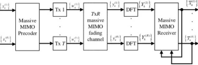
This paper focus on massive MIMO scenario, as depicted in Figure 1, which concerns the transmission between a transmitter with T antennas and a receiver with R antennas.
(1) n w ( )T n w DFT . . . (1) n y (1) k Y Massive MIMO Receiver (1) n x ( )R n x DFT ( )R n y Yk( )R . . . . . . Tx 1 Tx T TxR massive MIMO fading channel Massive MIMO Precoder (1 ) k x ( )R k x
Figure 1 – Block Diagram of SC-FDE m-MIMO using Precoder This system can be employed between a Base Station (BS) and a Mobile Terminal (MT) with R receiving antennas, to send multiple streams of data. This paper focus on the scenario with R data streams, where T≫R. Moreover, the uplink scenario can also be considered by the proposed system, as
long and the MT has enough power processing capability to implement the precoding. Since the proposed pre-processing algorithms based on MRT and EGT are very simple, such uplink scenario can easily be implemented.
Using the matrix-vector representation, we can express (1) for m-MIMO, using the corresponding frequency-domain block as
1
,..., R T
k Yk Yk k k k
Y H W N (5)
where H denotes the R Tk channel matrix for the kth
frequency, with
r t th, element H kr t, .The transmitted symbols Wk Wk 1,...,Wk T T, are those subject to precoding, defined by
k k k
W B X , (6) where B denotes the Tk precoding matrix, and the data R
symbols Xk Xk 1,...,Xk R T.
Depending on the algorithm employed, the precoding matrix k
B can be computed as:
1. Using the Zero-Forcing Transmitter (ZFT)2 algorithm
k B comes:
1 H H k k k k B H H H (7) 2. Using the MRT algorithm Bk comes:/ H k k T
B H (8) where T stands for the number of transmitting antennas.
3. Using the EGT algorithm Bk comes:
exp arg H /
k j k T
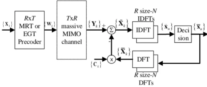
B H . (9) A disadvantage of the ZFT relies on the need to compute the pseudo-inverse of the channel matrix, for each frequency component, which corresponds to a high processing power capability. This paper mitigates this limitation by using the MRT and EGT algorithms. Nevertheless, a certain level of interference is generated, which degrades the performance, especially for moderate values of T R . Such interference can / be mitigated by employing the proposed iterative receiver that performs interference cancellation, as detailed in [23], resulting in an improved performance.
The iterative receiver (interference canceller), depicted in Figure 2, considers
k k k k
X Y C X (10) where the frequency domain estimated data symbols are
1
,..., R T k Xk Xk
X . The interference cancellation matrix k
C can be computed by
k k k
C H B I (11) where I is an R R identity matrix.
2ZFT refers to the ZF algorithm implemented as precoding, at the transmitter side. R size-N DFTs R size-N IDFTs Yk x Ck
Xk DFT + - xn Xk Deci sion IDFT RxT MRT or EGT Precoder xn TxR massive MIMO channel Wk XkFigure 2 – Block Diagram of m-MIMO Chain with Receiver and Interference Cancellation associated to Precoder
This interference canceller is implemented using
0,..., 1
k X XN
X , with X denoting the frequency-domain k
average values conditioned to the FDE output for the previous iteration [7], with Xk DFT
xn . Note that xn can be obtained as defined in [23].For the first iteration there is no information about the transmitted symbols and Xk 0.The signal and system description of the proposed m-MIMO using a post-processing, instead of pre-processing, is described in [23].
IV. CHANNEL ESTIMATION
A. Channel Estimation Using Conventional Pilots
Let us first assume that Xk 0, i.e., there is no data overlapping the training block, as in conventional schemes. In that case, we could estimate the channel frequency response as follows [7]: , * 2 2 r t TS t r k k k TS Y X H (12) 2 TS
stands for the power of the training sequences, i.e., pilots (TS stands for training sequence). Moreover, Yk r stands for signal at the rth received antenna
r1, 2,..,R
, and Xk t TSdenotes the training sequence transmitted by the tth transmit antenna
t1, 2,..,T
. If the training sequences associated to different transmit antennas are orthogonal, i.e., *
0 TS m TS q k k
X X mq, (13) then there is no interference between antennas when estimating the corresponding channels (e.g., by using disjoint sets of subcarriers for different antennas). This leads to
k k k
H H (14) The channel estimation error k is Gaussian-distributed, with zero-mean and
2 2 2 E N k TS (15) with 2
2 E 2 N Nk and with 2 TS 2/ 2
TSX
k
, as defined in [17].Since the channel impulse response is shorter than the cyclic prefix (which is just a fraction of the block duration), we could employ training blocks that are shorter than the standard data blocks. Alternatively, we could use the enhanced channel estimates as [9] [24] [25] ,
,
=DFT
t r t r k n nH
h
w
, (16) where w n 1 if the nth time domain sample is inside the cyclic prefix and 0 otherwise. In this case, the SNR at the channel estimates is improved by a factor T/TG, with T and TGdenoting the duration of the useful part of the block and the cyclic prefix, respectively.
B. Channel Estimation Using Implicit Pilots
Let us consider now the use of superimposed pilots, i.e., 0
k
X for the subcarriers with pilots. In the following we will assume that [21]
2
2 2 E / 2 E / 2 D Xk N xn , (17) where 2 D stands for the power of the data. Moreover, it is assumed that [21]
2
2 2 E TS / 2 E TS / 2 TS Xk N xn . (18)Clearly, we will have interference between data symbols and pilots, which leads to performance degradation. To overcome this problem, we can employ pilots with relatively low power and average the pilots over a large number of blocks so as to obtain accurate channel estimates. This is very effective since the data symbols have usually zero mean and different data blocks are uncorrelated. Naturally, there are limitations on the length of this averaging window, since the channel should be constant within it (not to mention the associated delays). Once we have an accurate channel estimate, we can detect the data symbols, removing first the signal associated to the pilots. Let us assume a frame with NT time-domain blocks, each with N subcarriers. If the cyclic prefix of each FFT block has
/
G G
N NT T samples we will need NG equally spaced frequency-domain pilots for the channel estimation. For pilot spacings in time and frequency NT and NF , respectively, the total number of pilots in the frame is given by
Frame T TS F T N N N N N . (19) This means that we have a pilot multiplicity or redundancy of
Frame TS T R G G F T N N N N N N N N (20) To avoid significant performance degradation due to channel estimation errors, SNR associated to the channel estimation,
given by 2 2
est
SNR NRTS/D, should be much higher than
the SNR for the data 2 2
data
SNR D/N.
For the first iteration, an initial channel estimation is obtained just by correlating the received signal Yk r Rx with the pilots, by using (12) and then (16).
For the second iteration, the data symbols are removed from the received blocks, i.e.
r TS r Rx r D r Rx t r, t
k k k k k k
Y Y Y Y H W
(21) and the channel estimation is improved by using (12) and (16). For the third and further iterations, the pilots are removed from the received blocks, as
r D r Rx r TS r Rx t r, t TS
k k k k k k
Y Y Y Y H X
(22) and the average values of the data symbols will be used as pilots for obtaining the channel frequency response estimate
1 1 * , 2 1 i r D i t i t r D k k k i t k Y W H W (23) where Wk t is taken from Wk Wk 1,...,Wk T T, the matrix of the frequency domain precoded signals generated by
k k k
W B X , as defined by (6), and where B denotes the k
T precoding matrix, as defined by (7), (8) or (9), R
depending on the precoding algorithm. Since using 0 might lead to noise enhancement effects in the channel estimates when Wk i 2is small, we will consider
2 2E Nk / E Wk
(24) If we have moderate to high SNR then
2 2 2 i k TS W (25) and we could use . 0
Finally, HkTS and D k
H , i.e., the channel estimates obtained from the training sequences and from the data aided, can be combined to provide the normalized channel estimates with minimum error variance, as defined by
2 2 , , 2 2 TS D TS D D k TS k TS D k k k D TS H H H H (26) where 2 2 2 , 2 , 2 2 TS D D TS k TS D D TS E (27)
V. RECEIVER DESIGN FOR MIMODETECTION AND CHANNEL ESTIMATION
A. Receiver Structure
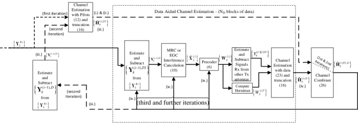
In this section we present a receiver with m-MIMO detection and channel estimation for SC-FDE with superimposed pilots. Without loss of generality it is assumed that there is a pilot for each subcarrier of each block of the frame (and for each transmit antenna), i.e., NF NT 1, leading to
Frame
TS T
N NN and a pilot multiplicity or redundancy of
/ /
Frame
R TS G T G
Channel Estimation with Pilots (12) and truncation (16)
Data Aided Channel Estimation - (ND blocks of data)
MRC or EGC Interference Cancelation (10) Precoder (6)
i k W Estimate and Subtract Signals Rx from other Tx antennas ( ),i TS k H
r i D
k Y
t* k W Compute Hermitian Channel Estimation with data (23) and truncation (16) Channel Combiner (26) ( ),i D k H ( )i TS D, k H (first iteration) (second iteration)
i k X
R x k Y Estimate and Subtract from
R x k Y
( 1),i D
k Y Estimate and Subtract from
R x k Y
( 1),i TS
k Y (second iteration)(third and further iterations)
(i.) & (ii.)
(iii.) (iv.) (iii.) (iv.) (iv.) (iv.) (iii.) ( 1),i TS k Y ( 1),i D k Y
Figure 3 – Block Diagram of m-MIMO Receiver with Interference Canceller and Channel Estimation, using Pre-Processing The principles behind this receiver are the following (see
indexes in the chains of Figure 3):
i. We first obtain the preliminary channel frequency response estimate, as in (12) 1 , * 2 2 r Rx t TS t r k k k TS Y X H
(29)This initial phase of detection and channel estimation is depicted in Figure 3, where different types of dashed lines represent the first and second iteration, while straight lines represent third and further iterations. Note that Hk i t r, denotes the channel estimate between the tth transmit and the rth receive antenna, and the ith iteration.
ii. Then, and as in (16), the channel estimate is
enhanced making the truncation
,
,
, DFT ,t r t r
k l n l n
H h w .
iii. Then we improve the channel estimation with the pilots, as defined by (21), estimate the signal regenerated from the data, subtract it from Yk r Rx and repeat i. and ii., using Yk r TS, instead of Yk r Rx. iv. The pilots / training sequences are removed from the
received frequency domain blocks, leading to [22]
1 Rx 1 t r, t TS
k k k k
Y Y H X
(30) and the blocks of detected samples Xk 1 are generated using the receiver with interference cancellation, as defined in Section IV. Thus, considering SC-FDE signals with interference canceller in the receiver, the decoded symbolscomes
( )i i i i
k k k k
X Y C X (31)
where C is defined in (11). Note that k Xk i 1
denotes the average signal conditioned to the output of the interference canceller, for the previous iteration
i 1
n
x . These average data values are then used to generate the average values of the transmitted symbols Xk 1 (as in ii. to v.) that will be used in the next iteration.
v. For the next iterations, the pilots are removed from
the received blocks, i.e.
r D r Rx r TS r Rx t r, t TS
k k k k k k
Y Y Y Y H X , and the
average values of the data symbols will be used as pilots for obtaining the channel frequency response estimate using data aided Hk i t r D, , as defined by (23) vi. As in ii., we use the approach of (16) to enhance the
channel estimates.
vii. Finally, we combine the channel estimations obtained from the training sequences with those obtained from the data (data aided), to provide the normalized channel estimates with minimum error variance, as defined by (26).
viii. The steps iv. to vii. are repeated for each iteration of the receiver.
VI. PERFORMANCE RESULTS
This section studies the Bit Error Rate (BER) performance obtained with m-MIMO using precoding, after the estimation of the channel parameters, using implicit pilots. SC-FDE transmission technique is considered. The BER is evaluated as a function of Eb/N0, where N0 is the one-sided power
spectral density of the noise and Eb is the energy of the transmitted bits (i.e., the degradation due to the useless power spent on the cyclic prefix is not included).
The BER was evaluated using Monte Carlo simulations, with QPSK modulation and with a block length of N = 256 symbols (similar results were observed for other values of N, provided
that N >> 1). We considered 10000 independent channel realizations for obtaining the average error rates. A Rayleigh
fading channel was considered with 16 uncorrelated equal power paths (it was assumed invariant during the block duration). The duration of the useful part of the blocks (N symbols) is 1μs and the cyclic prefix has duration 0.125μs. The impact of the CP duration in the performance is residual as long as the impulse response presents a high number of separated multipath components (with different delays with regard to the symbol period), which is the case of the current paper. For SC-FDE systems, up to four iterations of the receiver (detection and interference cancellation) was considered. Beyond four iterations, the performance improvement was almost negligible.
Perfect synchronization is assumed, as well as a transmitter with linear power amplification.
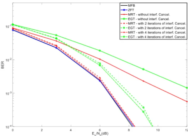
A. Ideal Channel Estimation
Figure 4 considers BER results for massive MIMO with 32 transmitting antennas and 2 receiving antennas (
32 2
), using precoding with ZFT, MRT and EGT, and ideal channel estimation. The Matched Filter Bound (MFB) performance is also shown. Results with and without interference cancellation as shown in Figure 4. In the scenario of Figure 4, the ZFT achieves a performance close to the MFB. Note that a regular SC-FDE receiver, without interference cancellation, is employed in the case of the ZFT. This receiver is used because the ZFT algorithm does not generate interference. It is viewed that, with 4 iterations of the interference cancellation, the performance obtained with the MRT approximates that of the MFB and ZFT, without having to invert matrices. Moreover, in the same scenario, the MRT algorithm achieves a performance better than that of the EGT.Figure 4 - BER results with
32 2
using Ideal Channel Estimation Figure 5 considers BER results for massive MIMO with 32 transmitting antennas and 8 receiving antennas (32 8
), using precoding, and ideal channel estimation. The conclusions that can be extracted from Figure 5 are similar to those obtained from Figure 4. Nevertheless, by increasing the number of receive antennas (which corresponds to an increase in the number of MTs or number of parallel streams of data sent to acertain MT), we are increasing the level of interference. Consequently, the performance results obtained with the MRT and EGT without interference cancellation are worse than those obtained in the
32 2
scenario. Nevertheless, by employing the new proposed interference cancellation, the performance results improve. The performance results obtained with the MRT and with 4 iterations of the interference canceller gets closer to those obtained with the MFB.Figure 5 - BER results with
32 8
using Ideal Channel Estimation Figure 6 considers BER results for massive MIMO with 128 transmitting antennas and 8 receiving antennas (128 8
), using precoding, and ideal channel estimation. As compared to Figure 5, we have increased the number of transmit antennas, while the number of receive antennas was kept unchanged, which resulted in a performance improvement for MRT/EGT, without and with interference cancellation.Figure 6 - BER results with
128 8
using Ideal Channel EstimationB. Channel Estimation Effects
This section presents results using implicit pilots for channel estimation, for m-MIMO using precoding. A comparison is also performed with the results obtained with ideal channel estimation and with the results obtained with conventional pilots.
Figure 7 shows the BER with implicit pilots, considering a single data block, a single iteration of the iterative channel estimator and a pilot power of -12 dB, as compared to the power of the data. Results with ideal channel estimation are also plotted in Figure 7. As can be seen, the results obtained with implicit pilots, using such parameters, are very poor. This occurs for several reasons:
• There is interference between data symbols and pilots, which leads to performance degradation. To overcome this problem, we can employ pilots with relatively low power and average the pilots over a large number of blocks so as to obtain accurate channel estimates. This is very effective since the data symbols have usually zero mean and different data blocks are uncorrelated. Naturally, there are limitations on the length of this averaging window, since the channel should be constant within it (not to mention the associated delays). In the following, results with 5 and 15 blocks are shown.
• A single iteration of the iterative channel estimator is probably not enough to achieve an acceptable estimate of the channel.
• The power of the pilot is, eventually, too low. In the case of implicit pilots, a trade-off of the pilot power needs to be achieved because: (1) the power of the pilot must be sufficiently low such that the interference generated by the pilots over the data symbols is not high and (2) the power of the pilot must be sufficiently high such that the initial channel estimate obtained with the pilots is good enough for the further iterations of the channel estimation to perform well.
Figure 7- BER results with
32 2
using Implicit Pilots with 1 data block, 1 iteration and a Pilot Power of -12 dBFigure 8 shows the BER performance results with implicit pilots, considering 5 data blocks, three iterations of the iterative channel estimator and a pilot power of -6 dB, -3 dB and 1, as compared to the power of the data. Results with ideal channel estimation are also plotted. As can be seen, the results obtained with implicit pilots, using such parameters, are better than those obtained in the scenario of Figure 7 (pilot power of -12 dB and -9 dB). The results obtained with pilot power of -3
dB are slightly better than those of power -6 dB. Except for the ZFT (that performs very poorly), the results obtained with pilot power of 0 dB are very close to those of power -3 dB. Using implicit pilots, the best overall performance is always the MRT, followed by the EGT. It is noted the performances obtained with MRT and EGT and a pilot power of -3 dB and 0 dB, which are very close to the ideal channel estimation counterparts. Finally, it is worth noting that while the ZFT with ideal channel estimation performs almost as good as the MFB, by considering unideal channel estimation, the performance obtained with the ZFT is always poor. Consequently, one can conclude that ZFT is not a good choice, neither because it performs poorly under unideal channel estimation nor because it is very demanding from the processing point of view (it requires computing the pseudo-inverse of the channel matrix, for each frequency component).
Figure 8 - BER results with
32 2
using Implicit Pilots with 5 data blocks, 3 iterations and a Pilot Power of -6 dB, -3 dB and 0 dBFigure 9 shows the BER performance results with implicit pilots, considering 5 data blocks, pilot power of -3 dB, with two versus three iterations of the iterative channel estimator. Results with ideal channel estimation are also plotted. As can be seen, with the exception of the ZFT, the performances obtained with 2 and 3 iterations of the channel estimator are very similar. This occurs for both MRT and EGT. It is also noted that such results are very close to the those obtained with the ideal channel estimation.
Figure 9 - BER results with
32 2
using Implicit Pilots with 5 data blocks, Pilot Power -3 dB, with 2 versus 3 iterations in the Channel Estimator Figure 10 shows the BER performance results with implicit pilots, considering 5 versus 15 data blocks, with a pilot power of 0 dB, and with three iterations of the iterative channel estimator. Results with ideal channel estimation are also plotted. As can be seen, the difference of performance between 5 and 15 blocks is almost imperceptible. Results obtained with ZFT, MRT and EGT with 5 and 15 blocks are very close to the performance obtained with ideal channel estimation.Figure 10 - BER results with
32 2
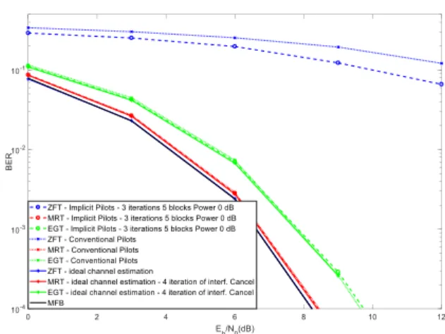
using Implicit Pilots with 5 versus 15 data blocks, 3 iterations and a Pilot Power of 0 dBFigure 11 shows the BER performance results with implicit pilots, considering 5 data blocks, with a pilot power of 0 dB, and with three iterations of the iterative channel estimator. The results of the implicit pilots are compared with those obtained with conventional pilots. Moreover, results with ideal channel estimation are also plotted. As can be seen, in the scenario of Figure 11, the results obtained with the implicit pilots are very similar to those obtained with conventional pilots. An exception is the ZFT, where the conventional pilots achieve a performance worse than those obtained with implicit pilots.
Figure 11 - BER results with
32 2
using Implicit Pilots with 5 data blocks, 3 iterations and a Pilot Power of 0 dB versus Conventional PilotsVII. CONCLUSIONS
The channel estimation for m-MIMO system was considered in this paper, using the SC-FDE transmission technique. m-MIMO using precoding with different algorithms was adopted, facilitating its usage in mm-Wave communications. We considered both conventional multiplexed pilots and implicit pilots for channel estimation purposes. To overcome the difficulties inherent to the interference levels between data and pilots that occurs with implicit pilots (superimposed pilots), we proposed an iterative receiver structure with interference cancellation and channel estimation. The results of implicit pilots were compared against those obtained with conventional pilots and with ideal channel estimation.
It was viewed that by using the proposed MRT and EGT we avoid the need to compute the pseudo-inverse of the channel matrix, for each frequency component, as required for the ZF algorithm. Since with MRT and EGT, a certain level of interference is generated, a novel iterative interference canceller was proposed, which suppresses such interference. With the proposed MRT and EGT, applied to m-MIMO as precoding algorithms, a performance very close to the MFB is achieved, especially with 4 iterations of the interference canceller.
Moreover, our performance results show that the use of implicit pilots, combined with the proposed iterative receiver, allows performances close to those obtained with ideal channel estimation, as well as close to those obtained with conventional pilots. While the ZFT is the scheme that achieves the best overall performance under ideal channel estimation conditions (although demanding high processing to invert matrices), by considering channel estimation (unideal channel estimation), the ZFT degrades heavily. The MRT tends to achieve the best overall performance, followed by the EGT, under unideal channel conditions, using channel estimation either with implicit pilots or with conventional pilots.
ACKNOWLEDGEMENTS
This work was supported by the Portuguese Foundation for the Science and Technology (FCT) under project UID/EEA/50008/2013.
REFERENCES
[1] Rusek, F., Persson, D., Lau, B.K., et al.: ‘Scaling up MIMO: opportunities and challenges with very large arrays’, IEEE Signal Process Mag., 2013, 30, (1), pp. 40–60.
[2] Boccardi, F., Heath, R., Lozano, A., Marzetta, T., and Popovski, P.: ‘Five disruptive technology directions for 5G’, IEEE Commun. Mag., 2014, 52, (2), pp. 74–80.
[3] Rappaport, T.S.; Shu Sun; Mayzus, R.; Hang Zhao; Azar, Y.; Wang, K.; Wong, G.N.; Schulz, J.K.; Samimi, M.; Gutierrez, F., ”Millimeter Wave Mobile Communications for 5G Cellular: It Will Work!,” IEEE Access, vol.1, no., pp.335,349, 2013.
[4] IEEE 802.11 Task Group AD, PHY/MAC Complete Proposal Specification, IEEE 802.11-10/0433r2, May 2010.
[5] S. Nie, G. MacCartney, S. sun, T. Rappaport, ”28 GHz and 73 GHz Signal Outage Study for Millimeter Wave Cellular and Backhaul Communications”, IEEE ICC’2014, Sydney, Australia, Jun. 2014.
[6] Rangan, S.; Rappaport, T.S.; Erkip, E.,”Millimeter-Wave Cellular Wireless Networks: Potentials and Challenges,” Proceedings of the IEEE , vol.102, no.3, pp.366,385, March 2014.
[7] M. Marques da Silva, R. Dinis, “Iterative Frequency-Domain Detection and Channel Estimation for Space-Time Block Codes” European Transactions on Telecommunications, John Wiley & Sons, Ltd., DOI: 10.1002/ett.1484, http://dx.doi.org/10.1002/ett.1484, Vol. 22, Issue 7, November 2011, pp. 339-351.
[8] M. Marques da Silva, A. Correia, R. Dinis, N. Souto, J. C. Silva, “Transmission Techniques for 4G Systems”, CRC Press Auerbach Publications, ISBN: 9781466512337, FL, USA, 2012 (http://www.crcpress.com/product/isbn/ 9781466512337).
[9] A.Gusmão, R.Dinis, J.Conceição and N.Esteves, “Comparison of Two Modulation Choices for Broadband Wireless Communications”, IEEE VTC’2000 (Spring), Tokyo, Japan, May 2000.
[10] Hoher P, Kaiser S, Robertson P. Pilot-symbol-aided channel estimation in time and frequency. IEEE Communication Theory Mini-Conference, 1997; 90–96.
[11] Lam C, Falconer D, Danilo-Lemoine F, Dinis R. Channel estimation for SC-FDE systems using frequency domain multiplexed pilots. IEEE 64th Vehicular Technology Conference, Montreal, Canada, 25–28 September 2006; 1–5.
[12] Orozco-Lugo A, Lara M, McLernon D. Channel estimation using implicit training. IEEE Transactions on Signal Proceesing 2004; 52(1): 240–254.
[13] Dinis R, Lam C, Falconer D. Joint frequency-domain equalization and channel estimation using superimposed pilots. IEEE Wireless Communications and Networking Conference, Las Vegas, USA, March 2008. [14] D. Borges, P. Montezuma, A. Ferreira and Rui Dinis, “Two Low Complexity MRC and EGC Based Receivers for SC-FDE Modulations with Massive MIMO Schemes”, Journal of Signal Processing Systems, Springer, 2017.
[15] Y. Li, K. Han, C. Dong, “A Multi-Band Low-Noise Transmitter with Digital Carrier Leakage Suppression and Linearity Enhancement”, IEEE Transactions on Circuits and Systems I, Vol. 60, Issue 5, May 2013.
[16] N.Benvenuto, R.Dinis, D.Falconer and S.Tomasin, "Single Carrier Modulation with Non Linear Frequency Domain Equalization: An Idea Whose Time Has Come – Again", IEEE Proceedings, Vol. 98, No. 1, page 69-96, Jan. 2010.
[17] R. Dinis, A. Gusmão, and N. Esteves, “On Broadband Block Transmission over Strongly Frequency-Selective Fading Channels”, Wireless 2003, Calgary, Canada, July 2003.
[18] R. Dinis, R. Kalbasi, D. Falconer and A. Banihashemi, “Iterative Layered Space-Time Receivers for Single-Carrier Transmission over Severe Time-Dispersive Channels”, IEEE Comm. Letters, Vol. 8, No. 9, pp. 579–581, Sep. 2004.
[19] M. Marques da Silva, A. Correia, R. Dinis, N. Souto, J. Silva – “Transmission Techniques for Emergent Multicast and Broadcast Systems” – CRC Press Auerbach Publications, 1st edition, June 2010, New York - USA, ISBN: 9781439815939;
[20] M. Tuchler, R. Koetter and A. Singer, “Turbo Equalization: Principles and New Results”, IEEE Trans. on Comm., Vol. 50, May 2002.
[21] M. Marques da Silva, F. A. Monteiro, "MIMO Processing for 4G and Beyond: Fundamentals and Evolution", CRC Press Auerbach Publications: ISBN: 9781466598072, FL, USA, June 2014
(http://www.crcpress.com/product/isbn/9781466598072).
[22] M. Marques da Silva, R. Dinis, A. Correia, “Iterative Frequency-Domain Receivers for STBC Schemes” – 2009 IEEE 70th Vehicular Technology Conference 2009 (VTC2009 - Fall), Anchorage, USA, September 2009. [23] M. Marques da Silva, R. Dinis, “A Simplified Massive MIMO Implemented with Pre or Post-Processing”, Physical Communications, Elsevier, Physical Communication-Elsevier Vol. 1, Nº 1, pp. 1-12, September, 2017, http://dx.doi.org/10.1016/j.phycom.2017.06.002.
[24] J. van de Beek et al., “On Channel Estimation in OFDM Systems”, Proceedings of IEEE Vehicular Technology Conference 1995 (VTC’95). [25] O. Edfors et al., “Analysis of DFT-Based Channel Estimators for OFDM”, Wireless Personal Communications, Volume 12, Number 1 / November, 2004, Springer Netherlands, 55-70.