Experimental Investigation on Laminated
Composite Leaf springs Subjected to Cyclic
Loading
S.Rajesh1 and G.B.Bhaskar2 1, 2
Department of Mechanical Engineering, Tagore Engineering College, Chennai 600 127, Tamilnadu, India
1
Abstract – An automobile industry have an interest in replacement of conventional leaf spring with composite leaf spring to get better performance with less weight.This paper deals with by replacing the conventional leaf spring with composite leaf spring. The dimensions of an existing conventional steel leaf spring of a light commercial vehicle were taken to fabricate the special die which is further used to manufacture the composite leaf spring. A single leaf with constant cross sectional area similar to that of conventional leaf spring(CLS) in each case such as bidirectional glass fiber reinforced plastic (GFRP), bidirectional carbon fiber reinforced plastic (CFRP), bidirectional carbon-glass reinforced plastic (C-GFRP) and bidirectional glass-carbon reinforced plastic (G-CFRP) were fabricated by hand layup technique and tested by universal testing machine. By using universal testing machine, load per deflection and maximum load that a leaf spring can withstand were measured. The cyclic loading with specific duration was given to the above mentioned composite leaf springs by using a laboratory designed loading set up through milling machine. From the experimented results it was observed that if conventional leaf springs are replaced by composite leaf springs an appropriate amount of weight reduction and there by improved vehicle performance could be achieved.
Keywords − Composite leaf spring, cyclic loading, flexural strength, Composite materials, Weight reduction. I. INTRODUCTION
Now-a-days the main focus of automobile industry is weight reduction. The automobile industry have shown increased interest for innovations, any modification, or implementation to reduce weight .This is done because of good characteristics given by the composite materials such as damping quality, corrosion resistance high strength to weight ratio etc. Weight can be reduced by introduce of better materials, better manufacturing process and optimization of design. So the composite are used as a material in place of conventional leaf spring. By using the composite materials in leaf spring it reduces the weight by 70%.This helps the vehicle with increasing fuel efficiency and riding qualities to be improved. Several researchers are devoted in the application of composite materials in automobile.
An author showed that increase in stiffness , natural frequency and reduced in stress , weight in composite leaf spring[1-5].Researchers have presented a genetic algorithms for optimal design of composite leaf spring .They found that huge weight was reduced in existing spring weight on optimization using genetic algorithms[6].An author described the design and manufactured of a functional composite spring for a solar powered light vehicle .Many testing was carried out during actual driving condition. They found that by placing of rubber pads on inside surfaces of the blades to cushion bottoming of the spring. It will reduces the impact load transferred to the chasis while suspension reaches the full deflection [7].For the freight rail application the researchers shows the paper in the design evolution process of a composite leaf spring. They described the three design of eye end attachment for a composite leaf spring [8].Author demonstrated for the application of light and heavy trucks composites elliptical spring meet the requirements with substantial weight saving. Adequate works have been carried out in the past two decades on design ,analysis and optimisation on composite leaf spring[9-11]. C.Subramanian et al fabricated the discontinuous fiber reinforced thermoplastic composite leaf spring by injection moulding and investigated the short term flexural creep performance.HRZ model was used for the creep performance evaluation. Results shows that HRZ model was found to be useful for predicting the short term creep performance[12]
The results shows that soderberg’s approach shows a maximum value of life cycles compared to the others [14].The author concluded by comparing steel and composite leaf spring under static loading condition by modelling and analysis. From the result it was found that mono composite leaf spring was so effective than steel leaf spring [15].
In this present work, three –leaf steel springs used in Tata ace mini truck is replaced with the composite leaf spring, that is made of bidirectional glass fiber reinforced plastic (GFRP), bidirectional carbon fiber reinforced plastic (CFRP), bidirectional carbon-glass reinforced plastic (C-GRP), and bidirectional glass-carbon reinforced plastic (G-CRP). The dimensions of center leaf for both steel leaf spring and composite leaf spring are considered to be same. The primary objective is to compare the load, deflection and weight saving of the composite leaf spring. Further the composite leaf springs are tested for its left over strength, with the introduction of cyclic loading. For this analysis, a cam like arrangements has been designed and fabricated to expose cyclic loading for the leaf springs through milling machine.
II. MATERIAL PREPARATION
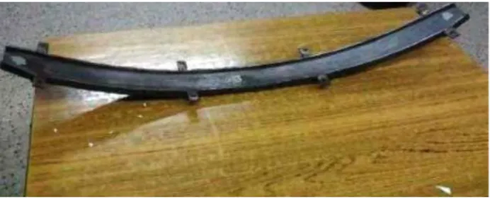
The dimensions of an existing conventional middle steel leaf spring of a Tata ace mini truck were taken and accordingly die is fabricated as shown in the Figure 1. By using the hand layup method, the GFRP laminates, CFRP laminates were made as per the following procedures. The glass fiber of 600gsm of bidirectional are taken and cut into 18 layers of size 900mm x 60mm. Then the resin combination of LY556 epoxy resin and HY951 hardener is mixed in the ratio of 10: 1 by weight. Wax coating was applied on the surface of the die to get good surface finish and also its helps during removal of the leaf from the die. Layers of the fabric mat are stacked by one over the other until the required thickness has been reached. In between the layers, resin mixture was poured and rolled out by using rollers to remove the entrapped air bubbles. Care was taken to ensure complete wetting of fibers and removal of en trapped air and excess resin. 18 layers of glass fiber mats were placed over another with the resin mixture on the special die. A wax coated steel plate of similar dimension of leaf spring was placed on the top of the laminate with same counter weight, so as to ensure the uniform distribution of resin mixture and to get good surface finish of the composite leaf spring.
Fig 1. Die used for composite leaf spring fabrication
III. EXPERIMENTAL TECHNIQUES
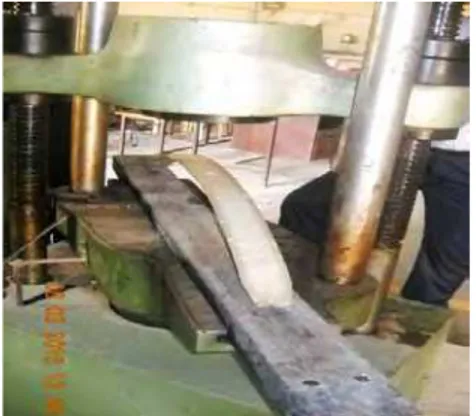
In this present study, the composite leaf spring deflection test is done by using 40 tons capacity of universal testing machine. Deflection for various loads, maximum load, and maximum deflection for mono glass fiber leaf spring, mono carbon fiber leaf spring, mono carbon- glass fiber leaf spring, and mono glass-carbon fiber leaf spring were measured by using universal testing machine. The spring is loaded from zero to the prescribed maximum deflection and back to zero. The load is applied at the Center of the spring. The vertical deflection of the spring Center is recorded in the load interval of 100N, for mono leaf spring as shown in the Figure 3. The deflection against loading of the various types of springs and weight of the springs are shown in the Table 1.
Fig. 3. Testing of composite leaf spring using Universal Testing Machine
TABLE I
Weight of the mono leaf springs
Further, the composite leaf springs are tested for its left over strength, with the introduction of cyclic loading. For this analysis, a cam like arrangements has been designed and fabricated to expose cyclic loading for the leaf springs through milling machine. The maximum deflection among the composite leaf spring is fabricated and approximately taken as 60mm with reference to the Table 2.
TABLE 2
Deflection test for various leaf spring
Load in N
Deflection in mm
Conventional Leaf
Glass fiber Leaf
Carbon fiber
leaf
Carbon - glass leaf
Glass - carbon leaf
100 6 9 7 8 7
200 9 18 15 20 14
300 14 31 29 32 23
400 18 42 40 41 30
500 24 55 53 50 41
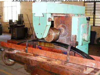
Hence initial cyclic loading of 1/3rd total deflection for specific duration was given to the composite leaf springs through the laboratory designed cam setup that is shown in the figure 4.
Leaf Weight in kg
GFRP 0.690
CFRP 0.720
G- 0.782
C- 0.740
Fig. 4. Cam arrangement set up for cyclic loading in milling machine
The cyclic loading frequency was fixed as 63 cycles per minute. By increasing the exposure time, the number of cycles of loading was increased. As initial trial, each category of specimens are given 3780 cycles of loading and is eventually tested for its load bearing capacity against deflection using universal testing machine as shown in Table 3.
TABLE 3
Deflection at 3780 cycles of loading
Load in N Deflection in mm
Glass fiber leaf Carbon fiber leaf Carbon - glass leaf Glass - carbon leaf
100 9 7 8 7
200 17 15 18 14
300 26 23 20 21
400 34 31 27 26
500 41 39 36 33
TABLE 4
Deflection at 7560 cycles of loading
Load in N Deflection in mm
Glass fiber leaf Carbon fiber leaf Carbon - glass leaf Glass - carbon leaf
100 8 6 7 7
200 16 15 18 14
300 25 20 20 19
400 32 28 26 25
500 39 37 34 31
TABLE 5
Deflection at 11340 cycles of loading
Load in N Deflection in mm
Glass fiber leaf Carbon fiber leaf Carbon - glass leaf Glass - carbon leaf
100 8 6 6 5
200 15 14 16 14
300 24 19 20 18
400 30 25 25 23
500 37 35 32 30
Similarly, by increasing the exposure time, the cyclic loading was increased to 7560 cycles as shown in the Table 4, and 11340 cycles and tested accordingly as above shown in the Table 5.
IV. RESULTS AND DISCUSSION
maximum load to obtain the load-deflection curve. The load-deflection curves for various mono leaf springs are shown in the Figure 5.
100 200 300 400 500
0 10 20 30 40 50 60
D
ef
lect
io
n
(
m
m
)
Load (N)
Conventional leaf
Glass fiber leaf Carbon fiber leaf Carbon - Glass leaf Glass - Carbon leaf
Fig. 5. Load Vs Deflection curve
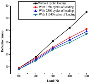
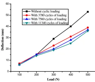
From the above graph, by comparing the steel leaf spring and composite leaf spring, it was observed that 62.5% of loads are beared by composite leaf spring. But at the same time, 71% of weight is reduced by the composite leaf spring. Hence the composite leaf springs are further tested for its load bearing strength against cyclic loading. For this analysis, a cam like arrangement has been designed and fabricated to expose the cyclic loading for the various composite leaf springs through milling machine. As the initial trial, each category of specimen i.e. various composite leaf spring are given 3780 cycles of loading with a constant deflection of 20mm, using milling machine and eventually tested for the load bearing capacity. Similarly by increasing the exposure time, the cyclic loading was increased to 7560 cycles and 11340 cycles and load carrying capacity test was repeated as above. The load deflection curve for the four types of composite leaf springs namely GFRP, CFRP, C-GFRP and G-CFRP are shown in the Figure 6, Figure 7, Figure 8 and Figure 9 respectively.
100 200 300 400 500
10 20 30 40 50 60
D
ef
lect
io
n
(
m
m
)
Load (N)
Without cyclic loading With 3780 cycles of loading With 7560 cycles of loading With 11340 cycles of loading
100 200 300 400 500 0
10 20 30 40 50 60
D
ef
lect
io
n
(
m
m
)
Load (N)
Without cyclic loading With 3780 cycles of loading With 7560 cycles of loading With 11340 cycles of loading
Fig.7. The deflection test for mono carbon leaf spring
100 200 300 400 500
0 10 20 30 40 50
D
ef
lect
io
n(
m
m
)
Load (N)
Without cyclic loading With 3780 cycles of loading With 7560 cycles of loading With 11340 cycles of loading
Fig. 8. The deflection test for mono Carbon–Glass leaf spring
5 10 15 20 25 30 35 40 45
D
ef
lect
io
n
(
m
m
)
From these graphs it was observed that the all four types of laminated composite leaf springs have the load bearing capacity of 500N.
It is well understood that for specific amount of load bearing capacity, the composite leaf springs produces low order of deflection. This can be revealed that the composite leaf springs can take more amount of load than the conventional steel leaf spring for the constant specified deflection. The reason for this increasing load bearing capacity of the composite springs may be due to toughening of reinforcement fibers that are taking place in the laminates with the application of cyclic loading, up to certain limit. Also among the composite leaf springs, the glass – carbon hybrid composite leaf spring can take more amount of load than others as shown in the fig. 6 to fig. 9. Hence it can be concluded that, the composite leaf spring would be better replacement material for the conventional steel leaf springs towards lesser deflection and higher load bearing capacity.
V. CONCLUSION
The fabrication of mono composite leaf spring was done by using hand layup method. The deflection test was carried out for mono composite leaf spring of all categories by using the universal testing machine. A cam like arrangement has been designed and fabricated to expose the cyclic loading for the leaf spring, through milling machine. After applying the cyclic loading such as 3780 cycles, 7560 cycles and 11340 cycles using milling machine, the deflection test was conducted. From the results, it is found that load bearing capacity is increased after applying the cyclic load in all types of composite leaf springs. The composite leaf springs can take more amount of load than the conventional leaf spring for constant specified deflection. Also among the composite leaf springs, the glass – carbon hybrid composite leaf spring can take up more amount of load than others. The composite mono leaf spring reduces the weight by 71% for glass/epoxy, 70% by carbon/epoxy, 67% for carbon-glass/epoxy and 68% for glass-carbon/ epoxy over the conventional leaf spring. If these kind of composite leaf springs are replaced in the automobiles, an improved vehicle performance will be obtained with appropriate load bearing properties due to the lower weight.
REFERENCES
[1] Senthilkumar.M, Vijayarangan.S, “Static analysis and fatigue life prediction of steel and composite leaf spring for light passenger vehicles”, Journal of scientific and industrial research, pp. 128-134, 2006.
[2] Shokreih.M, Davood Rezzaei, “Analysis and optimization of a composite leaf spring”, International journal of Composite structures, pp. 317-325, 2003.
[3] Siva Shankar.G, Vijayarangan.S, “Mono composite leaf spring light weight vehicle –Design, end joint analysis and testing”, International journal of material science, Vol 12, 2006.
[4] Senthilkumar.M, Vijayarangan.S,” Analytical and experimental studies on fatigue life prediction of steel and composite multi-leaf spring for light passenger vehicles using life data analysis”, International Journal of material science, Vol 13, 2007.
[5] Pankaj Saini. Ashish Goel. Dushyant Kumar. “Design and analysis of composite leaf spring for light vehicles”.International Journal of Innovative Research in Science, Engineering and Technology,Vol 2, Issue5, May 2013.
[6] Rajendra.L, Vijayarangan.S, “Optimal design of a composite leaf spring using genetic algorithms”, International journal of composite and structures, pp.1121-1129, 2001.
[7] Erol Sancaktar. Mathieu Gratton . “Design, analysis and optimization of composite leafs for light vehicle applications”, International Journal of Composite Structures, pp. 195-204. 1999.
[8] J. P. Hou, J.Y.Cherruault, I.Nairne, G. Jeronimidis, R. M. Mayer, “Evaluation of eye end design of composite leaf spring for heavy axle loads”, International journal of composite and structures, pp.351-358, 2007.
[9] Mahdi.E, Alkoles, O.M.S, Hamouda, A.M.S, Sahari, B.B, Yonus.R, Goudah, G, “Light composite elliptic springs for vehicle suspension”, International journal of composite structures. pp. 24-28, 2006.
[10] Goudah, Mahdi.E, Abu Talib.A.R, Mokhtar A.S, and Yunus.R “Automobile compression composite elliptic spring”, International journal of Engineering and Technology , Vol .3, pp 139-147 .2006.
[11] Abdul Rahim Abu Talib, Aidy Ali, Goudah.G, Nur Azida Che Lah, A.F.Golestaneh, “Developing a composite based elliptic spring for automotive applications”, International journal of Materials and Design , pp 475-484. 2010.
[12] C.Subramanian, S.Senthilvelan, “Short term flexural creep behaviour and model analysis of a glass fiber reinforced thermoplastic composite leaf spring. Journal of Applied Polymer Science, PP 3679- 3686.
[13] Ravikumar.V, Lalitha Narayana.R, Ch. Srinivas “Analysis of natural composite leaf spring” InternationalJournal of Latest trends in Engineering and Technology, Vol 3. Issue 1, 2013.
[14] U.S.Ramakanth. K.Sowjanya. “Design and analysis of automotive multi –leaf spring using composite materials” International Journal of Mechanical Production Engineering Research and Development, Vol. 3, pp 155-162, 2013.