Abstract
In this paper, the behavior of the intertwined shear and patch loading mechanisms in transversally stiffened steel plate girders is described. The phenomenological insight depicted in this paper shows the influence of the web thickness and the flange yield strength as well as the influence of the transverse stiffeners on the stress distribution, the critical loads and on the equilibrium path of this particular type of loading. A previously validated numerical model is used systematically as a simulation tool. Stress-, strain-, force- and displacement fields are exploited for the sake of infer-ring and idealizing the most valuable features of the depicted mechanical model.
Keywords
Patch loading, shear buckling, steel plate girders, plate buckling.
Mechanical Behavior of the Shear-Patch
Loading Interaction on Transversally
Stiffened Steel Plate Girders
1 INTRODUCTION
Steel plate girders have been studied profusely in last decades. The usage of such structures in the civil engineering world is vast: numerous steel and composite bridges as well as a great number of buildings worldwide are nowadays totally or partially assembled with steel girders. Steel plate gird-ers may be designed with symmetric or unsymmetric I-sections or box girdgird-ers.
In bridges, I-shaped steel girders are routinely assembled with slender plates for the webs
(rela-tively high values of hw/tw) and with stocky flanges (low values bf/tf). This combination leads to a
high flexural capacity for a relatively low weight, which is of an utmost importance in the optimal design of steel structures. There are, however, issues concerning the stability of the plates assem-bling the girders. Occasionally, these elements must be stiffened both transversally and longitudi-nally by welding additional plates that enhance considerably the overall and local behavior of these elements. From the design perspective, girders assembled with stocky web plates may lead to less stiffening (reducing the labor cost and welding but increasing the weight and cost of the steel
struc-Rolando Chacón
C/Jordi Girona 1-3 Campus Nord UPC. Universitat Politècnica de Cata-lunya. Barcelona, Spain
Latin American Journal of Solids and Structures 11 (2014) 1721-1743
ture) whereas slender web plates may lead to lighter structures that must adequately be stiffened for the sake of accomplishing all ultimate and serviceability limit states of the design. Construction-al guides covering the vast majority of topics deConstruction-aling with stability and plate girders have been
presented by Dowling et al. (1992), Galambos (1992), Dubas and Gehri (1986) and Beg et al.
(2010). Among the stability checks, shear buckling and patch loading have been identified as major verifications to be considered in most design codes (EN1993-1-5, 2005; AASHTO, 2009). Research in both topics has been considerably active in both cases. As a result, the vast majority of verifica-tions found in current design guidelines are based upon the results obtained by numerous research-ers.
The basis of the shear buckling phenomenon have been depicted in the USA by Basler (1960)
and in Europe by Porter et al. (1975), Rockey and Skaloud (1972) and Höglund (1971). The main
conclusions presented by these researchers are nowadays implemented in both European and North, Central and South American guidelines. As a result, the shear buckling mechanical behavior is well-known for girders with largely spaced and closely spaced transverse stiffeners (see sub-section 2.1). In addition, a significant amount of papers dealing with this subject have been published and with the advent of numerical methods, and thus, the state-of-the-art of the field has increased considera-bly. Recent research concerning shear buckling includes more sophisticated topics such as i) the
behavior of hybrid steel plate girders subjected to shear by Barker et al. (2002) and by Azizinamini
et al. (2007), ii) the behavior of stainless steel plate girders by Real et al. (2007), iii) the behavior of
tapered steel girders subjected to shear by Bedynek et al. (2013) or iv) the behavior of sinusoidally
corrugated steel plate girders by Eldib (2009).
Similarly, the basis of the patch loading phenomenon have primarily been established in Europe by Roberts and Rockey (1979), Markovic and Haydn (1992), Lagerqvist (1995), Graciano (2003) and in the USA by Elgaaly (1983) and by Duerr (2003). The main conclusions presented by these researchers are nowadays implemented in both European and North-, Central- and South American guidelines. Research concerning more sophisticated topics such as i) the behavior of hybrid steel
girders subjected to patch loading by Chacón et al. (2011) or ii) the behavior of steel girders
sub-jected to eccentric patch loading by Šćepanović et al. (2009) is also available. For the patch loading
case, however, the mechanical behavior of girders with largely spaced transverse stiffeners is well known whereas for closely spaced transverse stiffeners, research has been active only recently. The behavior of steel plate girders with closely spaced transverse stiffeners has been studied to a lesser extent than for girders with moderately- to largely spaced elements. One of the reasons of this lack of research may be that it has been historically assumed that girders with closely spaced transverse stiffeners are rather infrequent in bridge design.
The definition of the distance between transverse stiffeners as large or close is particularly cru-cial for the definition of the patch loading resistance. Largely spaced transverse stiffeners do not contribute to the resistance to patch loading (see sub-section 2.2) whereas closely spaced elements allow a considerable redistribution of stresses within the loaded and adjacent panels (see sub-section
2.3). Previous works presented by Chacón et al. (2013a,2013b) show that for girders with ratios
a/hw=1,0 (a relatively frequent proportion in bridge design), their resistance to patch loading is
Latin American Journal of Solids and Structures 11 (2014) 1721-1743
In this paper, the previous study is generalized to a set of variations of the geometrical
propor-tions (web slenderness hw/tw and transverse stiffeners thickness ts) such as for some cases,
shear-patch loading interaction is observed on the directly loaded and on the adjacent panels (DLP and AP, respectively). The study is performed on the basis of a vast parametric study developed by the author using a commercial FE-package (Abaqus Simulia, 2013). The numerical simulations are per-formed by following the EN1993-1-5-C (2005) recommendations concerning the designer-assumed initial conditions on plate buckling problems. A phenomenological insight of the mechanical behav-ior shows the potential stress redistribution on the loaded and over the adjacent panels. The study is limited to transversally stiffened elements with no longitudinally welded additional plates.
2 STEEL PLATE GIRDERS SUBJECTED TO SHEAR OR PATCH LOADING
Steel plate girders are generally designed for resisting high flexural loads. At particular cross-sections along the girders, high shear forces and/or concentrated forces may be applied. The former case is expected to occur at support sections near the bearings. The latter case is usually found during construction process of bridges (bridge launching in particular) when unstiffened
cross-sections bear significant concentrated loads over short distances ss. Figure 1 displays the main
vari-ables governing the behavior of both types of loadings. In particular, the web slenderness (hw/tw)
and the aspect ratio (a/hw) are the primary variables though additional features such as the steel
yield strengths (fyf, fyw and fys) as well as the loading length ss may also play a considerable role.
Qualitative and descriptive structural behavior for each case may be depicted via the equilibrium path. Sub-sections 2.1 to 2.3 describe succinctly the mechanisms depicted largely by several re-searchers.
ts,fys
a
ss
tw,fyw
tf,fyf
bf
h
w
Theoretical ly
ts,fys
a
ss
tw,fyw
tf,fyf
bf
h
w
Theoretical ly
(b)
(c) Loaded panel Adjacent panel
c-c c-c c
c ts,fys
a
(a)
tw,fyw
tf,fyf
h
w
d-d d
Latin American Journal of Solids and Structures 11 (2014) 1721-1743
Figure 1: Representation of steel girders subjected to (a) shear, (b) patch loading a>ly and (c) patch loading a<ly.
2.1 Shear
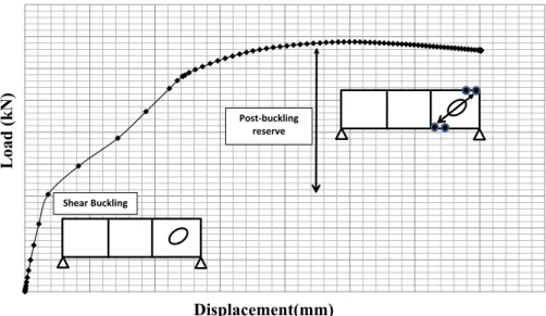
Figure 1(a) shows a doubly symmetric I-girder loaded on stiffened cross-sections. Both lateral pan-els are expected to bear high shear loads. These shear forces may generate an instability-related failure mode (shear buckling of such panels). The equilibrium path (load vs. out-of-plane displace-ment) of a typical incremental monotonic loading for such cases is displayed in Figure 2. Initially, a
linear relationship between P-δ governs the relationship. When critical stresses are reached, shear
buckling occurs due to increased compressive principal stresses at the center of the lateral panel. The out-of-plane displacement increases considerably (and non-linearly) and the panel is no longer able to resist compressive stresses. Subsequently, a post-critical mechanism involving tensile forces of the web and a formation of plastic hinges on the flange-to-stiffener juncture is formed. The total resistance involves the critical and the post-critical resistance. The design shear resistance given in different guidelines worldwide is based upon the aforementioned observations.
Figure 2: Equilibrium path of a steel girder subjected to shear.
2.2 Patch loading on girders with largely spaced stiffeners
Figure 1(b) shows a doubly symmetric I-girder subjected to a concentrated load on a loaded panel with largely spaced transverse stiffener. The typical failure mode of such element is web folding
over a theoretical distance (labeled in EN1993-1-5 as ly, the theoretical, effectively loaded length).
The equilibrium path (load vs. out-of-plane displacement) of a typical incremental monotonic
load-ing for such cases is displayed in Figure 3. Initially, a linear relationship between P-δ governs the
relationship. The web folds following an intertwined mechanism that involves plate instability and the formation of yield lines within the web.
Load
(k
N
)
Displacement(mm)
Shear Buckling
Latin American Journal of Solids and Structures 11 (2014) 1721-1743
Figure 3: Equilibrium path of a steel girder subjected to patch loading with largely spaced transverse stiffeners.
2.3 Patch loading on girders with closely spaced stiffeners
Figure 1(c) shows a doubly symmetric I-girder subjected to a concentrated load on a loaded panel with closely spaced transverse stiffener. The typical failure mode of such element with rigid stiffen-ers and moderately slender web is: web folding over the geometrical distance “a” as well as the for-mation of plastic hinges in the flange-to-stiffeners juncture. The equilibrium path (load vs. out-of-plane displacement) of a typical incremental monotonic loading for such cases is displayed in Figure
4. Initially, a linear relationship between P-δ governs the relationship. The web folds at F1 following
an intertwined mechanism that involves plate instability and the formation of yield lines within the web. The load increases a post-F1 reserve until these yield lines anchor in the flange-to-stiffener
juncture and four plastic hinges form hogging and sagging regions of the flange (F2).
Figure 4: Equilibrium path of a steel girder subjected to patch loading with largely spaced transverse stiffeners.
Load
(k
N
)
Displacement(mm)
Web folding
Load
(k
N
)
Displacement(mm) Web folding ly=a
Four plastic hinges Post‐F1 reserve
F1
Latin American Journal of Solids and Structures 11 (2014) 1721-1743
3 NUMERICAL MODEL
The numerical model implemented in the multi-purpose FE-based software Abaqus-Simulia (2013) was used as a simulation tool. The model was previously validated for patch loading and shear
sep-arately by comparing the numerical results with values obtained experimentally (Chacón et al.
2013a, Chacón et al. 2011 and Bedynek et al. 2013). Two types of procedures were performed,
ei-genvalue extractions for obtaining the elastic critical loads of the girders and incremental nonlinear analyses for obtaining the equilibrium path. Details concerning both cases are succinctly described in the following.
The main characteristics of the model are listed herein:
• Full linear integration, four-noded quadrilateral S4 elements from Abaqus libraries.
• Elastic-perfectly plastic material with no strain hardening.
• Structured meshes developed with an advanced front algorithm (size=10 millimeters).
• Geometrical nonlinearity.
3.1 Eigenvalue extraction
Abaqus contains capabilities for estimating the elastic buckling loads of structural systems by means of Eigenvalue extraction. The Eigenvalue buckling analysis is performed with Abaqus first storing the stiffness matrix at the state corresponding to the base state loading of the structure, then applying a small perturbation. The initial stress matrix resulting from the load is calculated, and then an Eigenvalue calculation (subspace method) is performed to determine a multiplier to the load at which the structure reaches instability. As a result, several Eigenmodes can be shaped with-in the with-initially straight plates. Each eigenvalue represents the amount of total energy of the system. Abaqus displays the results ranging from lower energy to greater energy with the corresponding buckling shape associated.
3.2 Nonlinear analyses
Latin American Journal of Solids and Structures 11 (2014) 1721-1743
4 PARAMETRIC STUDY
A total amount of 108 girders were simulated with the numerical model. The girders consisted of simply supported, initially straight, three-paneled specimens. The geometrical proportions were chosen inasmuch as a shear-patch loading interaction was observed for some cases (Table 1). For this purpose, the following variations and conditions were established:
• Closely spaced transverse stiffeners a<ly.
• Varying transverse stiffener relative rigidity ts/tw.
• Varying web slenderness hw/tw.
• Varying yield strength of the flange fyf.
• The numbering of the girders follow the fyf-tw-ts order (e.g., 235-3-10)
Table 1: Geometry of the numerically simulated prototypes. Set of variations
The analysis was performed for each girder following the procedure depicted in Figure 5. A numeri-cal simulation aimed at extracting the eigenvalues was performed on 36 initially straight girders
(since this procedure is defined over elastic prototypes, no variation of fyf was implemented for such
case). With the extracted eigenmodes, a linear combination of patch loading- and shear-related was subsequently introduced as the initial geometric imperfection for the nonlinear incremental proce-dure. The 108 girders were not, thus, initially straight but slightly perturbed. In all cases, the mag-nitude of the perturbation was scaled as 80% of the web thickness for the primary mode (patch loading) and 0,7·80% for the secondary mode (shear buckling). These magnitudes were chosen ac-cording to the recommendations suggested in EN1993-1-5-Annex C, concerning the use of finite elements in steel plated structures.
ss (mm) bs=bf (mm) a=hw (mm) tf (mm) fyw (N/mm2) fyf (N/mm2) tw (mm) ts (mm)
3 8
4 10
235
6 20
187,5 375 750 50 235 355
8 30
460
10 40
12 50
1 x 1 x 1 x 1 x 1 x 3 x 6 x 6
Latin American Journal of Solids and Structures 11 (2014) 1721-1743
Figure 5:Procedure for the development of the numerical simulations.
5 RESULTS
5.1 Eigenvalue extraction
Elastic critical buckling loads associated with 6 eigenmodes for 36 prototypes are displayed in Table 2. Remarkable results are highlighted within the table. Three different types of results are worth pointing out.
• For a given eigenmode (vertically highlighted border in table 2), the elastic critical
buck-ling load increases slightly with the stiffener thickness. Figure 6(a) displays the increasing
trend. The trend seems to be different for stiffeners with low values of ts than for
stiffen-ers with ts >20 mm, whose trend seems to be linear.
• For a given eigenmode, the elastic critical buckling load increases considerably with the
web thickness. Figure 6(b) displays the (expected) exponentially increasing trend. The elastic critical buckling loads for eigenmode 1 are highlighted in table 2 for different
val-ues of tw.
Figure 6:Elastic critical buckling load as a function of (a) ts and (b) tw. Increment=0
Initially straight three‐paneled
steel girder
Increment ‐‐‐> Web folding
Web folding+Shear buckling
M3=shear patch loading
Buckling analysis Nonlinear incremental analysis
M1=Eigenmode associated with
patch loading
Linear combination of modes
630 640 650 660 670 680 690 700 710 720 730
0 10 20 30 40 50 60
El
a
sti
c
cr
iti
ca
l
b
u
c
k
li
n
g
l
o
a
d
(k
N
)
ts (mm)
0 500 1000 1500 2000 2500 3000 3500 4000 4500
0 2 4 6 8 10 12 14
(k
N
)
Latin American Journal of Solids and Structures 11 (2014) 1721-1743
Table 2: Geometry of the numerically simulated prototypes. Set of variations.
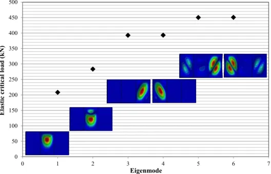
• The elastic buckling load increases for each mode (horizontally highlighted border in
ta-ble 2). Figure 7 displays the values and the modes for the highlighted girder. On the one hand, it is observed that modes 1-2 are both patch loading-related but differ slightly in magnitude. On the other hand, it is noticeable that 3-4 as well as 5-6 modes are symmet-rical and shear buckling-related (being practically identical in magnitude).
1 2 3 4 5 6
235-3-8 3 8 250 2,67 94,3 128,2 172,0 172,1 198,2 198,4
235-3-10 3 10 250 3,33 95,5 129,7 175,8 175,9 202,7 202,9
235-3-20 3 20 250 6,67 98,6 133,5 183,7 183,8 209,5 209,7
235-3-30 3 30 250 10,00 101,6 136,3 186,6 186,7 209,8 210,0
235-3-40 3 40 250 13,33 104,8 139,4 188,9 189,0 213,3 213,5
235-3-50 3 50 250 16,67 108,0 142,9 191,6 191,8 216,0 216,2
235-4-8 4 8 187,5 2,00 208,3 283,5 392,8 393,2 450,3 450,7
235-4-10 4 10 187,5 2,50 211,5 287,9 403,5 403,9 464,3 464,8
235-4-20 4 20 187,5 5,00 218,5 296,8 425,5 426,0 488,7 489,2
235-4-30 4 30 187,5 7,50 223,9 302,0 433,1 433,6 494,0 494,5
235-4-40 4 40 187,5 10,00 229,6 307,6 438,0 438,5 496,7 497,2
235-4-50 4 50 187,5 12,50 235,2 313,6 443,1 443,6 500,7 501,2
235-6-8 6 8 125 1,33 635,1 870,8 1236,4 1237,9 1389,2 1392,8
235-6-10 6 10 125 1,67 650,5 889,7 1286,6 1288,3 1462,4 1465,9
235-6-20 6 20 125 3,33 679,1 927,1 1386,0 1388,0 1591,9 1594,2
235-6-30 6 30 125 5,00 693,0 942,1 1418,1 1420,3 1621,4 1623,8
235-6-40 6 40 125 6,67 706,1 955,2 1435,8 1438,0 1633,3 1635,7
235-6-50 6 50 125 8,33 718,9 968,6 1450,5 1452,7 1644,1 1646,4
235-8-8 8 8 93,75 1,00 1397,3 1939,2 2729,3 2733,8 2994,4 2999,7
235-8-10 8 10 93,75 1,25 1437,3 1981,0 2883,8 2888,4 3217,9 3230,6
235-8-20 8 20 93,75 2,50 1524,2 2089,5 3186,4 3192,2 3647,3 3654,7
235-8-30 8 30 93,75 3,75 1555,8 2126,9 3281,1 3287,4 3751,7 3758,5
235-8-40 8 40 93,75 5,00 1581,3 2153,5 3329,6 3336,2 3792,2 3799,0
235-8-50 8 50 93,75 6,25 1604,8 2178,5 3365,4 3371,8 3820,4 3826,8
235-10-8 10 8 75 0,80 2583,8 3627,9 4889,5 4898,1 5013,2 5022,4
235-10-10 10 10 75 1,00 2652,3 3692,4 5312,0 5321,9 5815,2 5832,1
235-10-20 10 20 75 2,00 2848,9 3918,7 6041,4 6055,0 6865,7 6892,6
235-10-30 10 30 75 3,00 2916,8 4003,7 6266,0 6281,5 7151,5 7168,4
235-10-40 10 40 75 4,00 2962,4 4054,4 6376,9 6393,2 7262,6 7277,3
235-10-50 10 50 75 5,00 3001,6 4097,4 6452,7 6469,1 7330,1 7344,1
235-12-8 12 8 62,5 0,67 4283,0 6002,7 6025,3 6089,6 6721,1 6735,5
235-12-10 12 10 62,5 0,83 4378,1 6153,6 8577,4 8592,2 9016,9 9025,3
235-12-20 12 20 62,5 1,67 4731,8 6529,4 10125,0 10153,8 11395,5 11471,5
235-12-30 12 30 62,5 2,50 4867,9 6701,2 10587,0 10622,1 12020,6 12077,6
235-12-40 12 40 62,5 3,33 4946,6 6793,9 10809,1 10847,1 12258,3 12313,1
235-12-50 12 50 62,5 4,17 5008,5 6864,9 10954,0 10992,7 12393,3 12446,7
Elastic critical buckling load for each mode (kN) ts/tw
Latin American Journal of Solids and Structures 11 (2014) 1721-1743
Figure 7: Elastic critical buckling loads and modes for a given prototype.
• One magnitude to bear in mind is the M3/M1 ratio for buckling loads. If this ratio is
slow, the girder is more likely to present an intertwined shear-patch loading mechanism. Figure 8 displays these magnitudes as a function of the stiffness-to-web thickness for
dif-ferent values of tw. For the vast majority of cases, this ratio approaches 2,0. Noticeably,
though, girders with relatively flexible stiffeners present lower ratios, which may lead to higher shear-patch loading interaction. In sub-section 5.2, further exploitation of such re-sults is addressed.
Figure 8: Elastic critical buckling loads and modes for a given prototype.
0 50 100 150 200 250 300 350 400 450 500
0 1 2 3 4 5 6 7
El
a
sti
c c
ri
ti
cal
l
o
a
d
(
k
N
)
Eigenmode
1,30 1,50 1,70 1,90 2,10 2,30 2,50
0 5 10 15 20
El
a
sti
c
cr
iti
ca
l
b
u
ck
li
n
g
l
o
a
d
(k
N
)
t
s/t
wLatin American Journal of Solids and Structures 11 (2014) 1721-1743 5.2 Nonlinear response
The nonlinear response of 108 prototypes with varying web thickness, web slenderness and flange yield strength is studied via four characteristics. Figure 9 displays the location of key points whose stress or displacement values are extracted from:
• The equilibrium path: a P-δ plot in which P is the total vertical reaction force and δ is
the out-of-plane displacement in key points of the directly loaded panel (DLP, point i)
and the adjacent panels (AP, point j). In all plots, F1, the post-F1 reserve (labeled as ΔFf
in the literature) and F2 are identified.
• The evolution of the principal stresses in the AP (point j).
• The evolution of the vertical stresses in stiffeners (ST) at key points (point k).
• The evolution of the longitudinal stresses in the flanges (FL) of the DLP at key points
(where plastic hinges form, i.e., points l)
• The evolution of the deformed state throughout the equilibrium path.
Figure 9:Key lastic critical buckling loads and modes for a given prototype.
Moreover, table 3 displays key values for all studied girders such as:
• Geometrical proportions of the web and the stiffeners (web slenderness hw/tw ranging from
62,50 to 250 and stiffeners rigidity ts/tw ranging from 0,80 to 16,67).
• Elastic critical buckling loads associated to patch loading in DLP (M1) and to shear
buck-ling of the AP (M3).
• Identified value of F1 (web folding at DLP). This value is identified in all plots as the
point at which the slope of the P-δ changes its slope. Visual inspections as well as the first
numerical derivative in all P-δ plots are used in this identification.
• The ratios between the web folding F1 load and the aforementioned elastic critical loads.
Noticeably, these ratios range from 10 to 0,57 for M1 and from 6,19 to 0,26 for M3.
Gener-ally, the more slender the girder, the higher the ratio.
• The ultimate load capacity of the girders F2 and the post-F1 reserve ΔFf=F2-F1.
• The ratio ΔFf/ F2. For a given girder with comparable geometry, this ratio increases with
the ts/tw rigidity and with the flange yield strength fyf but decreases with the web
slender-ness hw/tw.
A systematic assessment of the aforementioned results is presented in the following.
Point i (DLP)
Latin American Journal of Solids and Structures 11 (2014) 1721-1743
Table 3:Results obtained. Fcr,num,M1 Fcr,num,M3 F1 F2 ΔFf
(kN) (kN) (kN) (kN) (kN)
235-3-8 250 2,67 94,3 172,02 815,19 8,64 4,74 1113,58 298,39 0,27 11,81 6,47
235-3-10 250 3,33 95,5 175,78 828,49 8,68 4,71 1149,33 320,84 0,28 12,04 6,54
235-3-20 250 6,67 98,6 183,69 895,46 9,08 4,87 1320,81 425,35 0,32 13,39 7,19
235-3-30 250 10,00 101,6 186,57 1022,61 10,07 5,48 1549,37 526,76 0,34 15,25 8,30
235-3-40 250 13,33 104,8 188,87 1075,29 10,26 5,69 1705,52 630,23 0,37 16,28 9,03
235-3-50 250 16,67 108,0 191,58 1106,00 10,24 5,77 1726,16 620,16 0,36 15,99 9,01
355-3-8 250 2,67 94,3 172,02 815,19 8,64 4,74 1224,88 409,69 0,33 12,99 7,12
355-3-10 250 3,33 95,5 175,78 828,49 8,68 4,71 1295,64 467,15 0,36 13,57 7,37
355-3-20 250 6,67 98,6 183,69 895,46 9,08 4,87 1523,99 628,53 0,41 15,45 8,30
355-3-30 250 10,00 101,6 186,57 1023,15 10,07 5,48 1793,11 769,96 0,43 17,65 9,61
355-3-40 250 13,33 104,8 188,87 1076,35 10,27 5,70 2211,82 1135,47 0,51 21,11 11,71
355-3-50 250 16,67 108,0 191,58 1185,32 10,98 6,19 2683,58 1498,26 0,56 24,86 14,01
460-3-8 250 2,67 94,3 172,02 815,19 8,64 4,74 1257,19 442,00 0,35 13,33 7,31
460-3-10 250 3,33 95,5 175,78 828,49 8,68 4,71 1384,60 556,11 0,40 14,51 7,88
460-3-20 250 6,67 98,6 183,69 895,46 9,08 4,87 1683,96 788,50 0,47 17,07 9,17
460-3-30 250 10,00 101,6 186,57 1023,15 10,07 5,48 1989,15 966,00 0,49 19,58 10,66
460-3-40 250 13,33 104,8 188,87 1076,35 10,27 5,70 2437,41 1361,06 0,56 23,26 12,91
460-3-50 250 16,67 108,0 191,58 1185,32 10,98 6,19 2859,02 1673,70 0,59 26,48 14,92
235-4-8 187,5 2,00 208,3 392,81 1241,03 5,96 3,16 1383,25 142,22 0,10 6,64 3,52
235-4-10 187,5 2,50 211,5 403,52 1257,63 5,95 3,12 1416,07 158,44 0,11 6,70 3,51
235-4-20 187,5 5,00 218,5 425,54 1339,94 6,13 3,15 1584,64 244,70 0,15 7,25 3,72
235-4-30 187,5 7,50 223,9 433,07 1401,00 6,26 3,24 1752,80 351,80 0,20 7,83 4,05
235-4-40 187,5 10,00 229,6 437,98 1477,44 6,44 3,37 1793,98 316,54 0,18 7,81 4,10
235-4-50 187,5 12,50 235,2 443,07 1171,61 4,98 2,64 1792,66 621,05 0,35 7,62 4,05
355-4-8 187,5 2,00 208,3 392,81 1240,76 5,96 3,16 1494,96 254,20 0,17 7,18 3,81
355-4-10 187,5 2,50 211,5 403,52 1253,51 5,93 3,11 1498,45 244,94 0,16 7,09 3,71
355-4-20 187,5 5,00 218,5 425,54 1343,59 6,15 3,16 1778,72 435,13 0,24 8,14 4,18
355-4-30 187,5 7,50 223,9 433,07 1407,03 6,28 3,25 2032,91 625,88 0,31 9,08 4,69
355-4-40 187,5 10,00 229,6 437,98 1485,41 6,47 3,39 2446,81 961,40 0,39 10,66 5,59
355-4-50 187,5 12,50 235,2 443,07 1172,16 4,98 2,65 2612,89 1440,73 0,55 11,11 5,90
460-4-8 187,5 2,00 208,3 392,81 1240,76 5,96 3,16 1532,53 291,77 0,19 7,36 3,90
460-4-10 187,5 2,50 211,5 403,52 1253,51 5,93 3,11 1508,56 255,05 0,17 7,13 3,74
460-4-20 187,5 5,00 218,5 425,54 1343,58 6,15 3,16 1924,83 581,25 0,30 8,81 4,52
460-4-30 187,5 7,50 223,9 433,07 1407,05 6,28 3,25 2220,89 813,84 0,37 9,92 5,13
460-4-40 187,5 10,00 229,6 437,98 1485,51 6,47 3,39 2655,97 1170,46 0,44 11,57 6,06
460-4-50 187,5 12,50 235,2 443,07 1355,00 5,76 3,06 3087,02 1732,02 0,56 13,12 6,97
235-6-8 125 1,33 635,1 1236,38 1217,47 1,92 0,98 1988,24 770,77 0,39 3,13 1,61
235-6-10 125 1,67 650,5 1286,65 1223,18 1,88 0,95 1995,32 772,14 0,39 3,07 1,55
235-6-20 125 3,33 679,1 1386,00 1238,76 1,82 0,89 2033,90 795,14 0,39 2,99 1,47
235-6-30 125 5,00 693,0 1418,13 1336,53 1,93 0,94 2060,46 723,93 0,35 2,97 1,45
235-6-40 125 6,67 706,1 1435,78 1366,56 1,94 0,95 2080,19 713,63 0,34 2,95 1,45
235-6-50 125 8,33 718,9 1450,48 1394,60 1,94 0,96 2091,01 696,41 0,33 2,91 1,44
355-6-8 125 1,33 635,1 1236,38 1217,47 1,92 0,98 2164,17 946,70 0,44 3,41 1,75
355-6-10 125 1,67 650,5 1286,65 1223,18 1,88 0,95 2218,41 995,23 0,45 3,41 1,72
355-6-20 125 3,33 679,1 1386,00 1238,76 1,82 0,89 2393,70 1154,94 0,48 3,52 1,73
355-6-30 125 5,00 693,0 1418,13 1336,53 1,93 0,94 2570,52 1233,99 0,48 3,71 1,81
355-6-40 125 6,67 706,1 1435,78 1366,56 1,94 0,95 2709,89 1343,33 0,50 3,84 1,89
355-6-50 125 8,33 718,9 1450,48 1394,60 1,94 0,96 2774,55 1379,95 0,50 3,86 1,91
460-6-8 125 1,33 635,1 1236,38 1217,47 1,92 0,98 2226,75 1009,28 0,45 3,51 1,80
460-6-10 125 1,67 650,5 1286,65 1223,18 1,88 0,95 2313,16 1089,98 0,47 3,56 1,80
460-6-20 125 3,33 679,1 1386,00 1238,76 1,82 0,89 2459,49 1220,73 0,50 3,62 1,77
460-6-30 125 5,00 693,0 1418,13 1336,53 1,93 0,94 2744,17 1407,64 0,51 3,96 1,94
460-6-40 125 6,67 706,1 1435,78 1366,56 1,94 0,95 3093,36 1726,80 0,56 4,38 2,15
460-6-50 125 8,33 718,9 1450,48 1511,00 2,10 1,04 3376,56 1865,56 0,55 4,70 2,33
ΔFf / F2F2/FM1 F2/FM3
Latin American Journal of Solids and Structures 11 (2014) 1721-1743
Table 3 (cont.):Results obtained. Fcr,num,M1 Fcr,num,M3 F1 F2 ΔFf
(kN) (kN) (kN) (kN) (kN)
235-8-8 93,75 1,00 1397,32 2729,25 1652,44 1,18 0,61 2303,70 651,26 0,28 1,65 0,84
235-8-10 93,75 1,25 1437,33 2883,80 1661,41 1,16 0,58 2315,63 654,22 0,28 1,61 0,80
235-8-20 93,75 2,50 1524,23 3186,35 1680,19 1,10 0,53 2359,33 679,14 0,29 1,55 0,74
235-8-30 93,75 3,75 1555,80 3281,06 1694,07 1,09 0,52 2392,58 698,51 0,29 1,54 0,73
235-8-40 93,75 5,00 1581,33 3329,65 1710,42 1,08 0,51 2417,22 706,80 0,29 1,53 0,73
235-8-50 93,75 6,25 1604,81 3365,37 1896,77 1,18 0,56 2440,75 543,98 0,22 1,52 0,73
355-8-8 93,75 1,00 1397,32 2729,25 1652,45 1,18 0,61 2816,00 1163,55 0,41 2,02 1,03
355-8-10 93,75 1,25 1437,33 2883,80 1661,43 1,16 0,58 2881,47 1220,04 0,42 2,00 1,00
355-8-20 93,75 2,50 1524,23 3186,35 1680,22 1,10 0,53 2951,31 1271,09 0,43 1,94 0,93
355-8-30 93,75 3,75 1555,80 3281,06 1694,10 1,09 0,52 3008,47 1314,37 0,44 1,93 0,92
355-8-40 93,75 5,00 1581,33 3329,65 1710,46 1,08 0,51 3061,78 1351,32 0,44 1,94 0,92
355-8-50 93,75 6,25 1604,81 3365,37 1898,77 1,18 0,56 3101,48 1202,71 0,39 1,93 0,92
460-8-8 93,75 1,00 1397,32 2729,25 1652,45 1,18 0,61 2923,35 1270,90 0,43 2,09 1,07
460-8-10 93,75 1,25 1437,33 2883,80 1661,43 1,16 0,58 2953,93 1292,50 0,44 2,06 1,02
460-8-20 93,75 2,50 1524,23 3186,35 1680,22 1,10 0,53 3179,05 1498,83 0,47 2,09 1,00
460-8-30 93,75 3,75 1555,80 3281,06 1694,10 1,09 0,52 3390,90 1696,80 0,50 2,18 1,03
460-8-40 93,75 5,00 1581,33 3329,65 1710,46 1,08 0,51 3541,22 1830,76 0,52 2,24 1,06
460-8-50 93,75 6,25 1604,81 3365,37 1898,77 1,18 0,56 3631,13 1732,36 0,48 2,26 1,08
235-10-8 75,00 0,80 2583,84 4889,53 2248,72 0,87 0,46 2666,76 418,04 0,16 1,03 0,55
235-10-10 75,00 1,00 2652,33 5312,04 2257,98 0,85 0,43 2680,88 422,90 0,16 1,01 0,50
235-10-20 75,00 2,00 2848,85 6041,39 2283,57 0,80 0,38 2726,68 443,11 0,16 0,96 0,45
235-10-30 75,00 3,00 2916,84 6265,97 2305,90 0,79 0,37 2768,46 462,56 0,17 0,95 0,44
235-10-40 75,00 4,00 2962,41 6376,92 2333,08 0,79 0,37 2803,68 470,60 0,17 0,95 0,44
235-10-50 75,00 5,00 3001,57 6452,72 2360,29 0,79 0,37 2830,99 470,70 0,17 0,94 0,44
355-10-8 75,00 0,80 2583,84 4889,53 2255,30 0,87 0,46 3210,15 954,85 0,30 1,24 0,66
355-10-10 75,00 1,00 2652,33 5312,04 2264,84 0,85 0,43 3266,80 1001,96 0,31 1,23 0,61
355-10-20 75,00 2,00 2848,85 6041,39 2291,17 0,80 0,38 3332,18 1041,01 0,31 1,17 0,55
355-10-30 75,00 3,00 2916,84 6265,97 2314,23 0,79 0,37 3385,87 1071,64 0,32 1,16 0,54
355-10-40 75,00 4,00 2962,41 6376,92 2342,29 0,79 0,37 3441,83 1099,54 0,32 1,16 0,54
355-10-50 75,00 5,00 3001,57 6452,72 2370,38 0,79 0,37 3481,04 1110,66 0,32 1,16 0,54
460-10-8 75,00 0,80 2583,84 4889,53 2255,30 0,87 0,46 3462,98 1207,68 0,35 1,34 0,71
460-10-10 75,00 1,00 2652,33 5312,04 2264,84 0,85 0,43 3649,89 1385,05 0,38 1,38 0,69
460-10-20 75,00 2,00 2848,85 6041,39 2291,17 0,80 0,38 3779,70 1488,53 0,39 1,33 0,63
460-10-30 75,00 3,00 2916,84 6265,97 2314,23 0,79 0,37 3854,58 1540,35 0,40 1,32 0,62
460-10-40 75,00 4,00 2962,41 6376,92 2342,29 0,79 0,37 3932,61 1590,32 0,40 1,33 0,62
460-10-50 75,00 5,00 3001,57 6452,72 2370,38 0,79 0,37 4007,38 1637,00 0,41 1,34 0,62
235-12-8 62,50 0,67 4283,02 6025,29 2707,41 0,63 0,45 3084,56 377,15 0,12 0,72 0,51
235-12-10 62,50 0,83 4378,08 8577,42 2715,84 0,62 0,32 3100,07 384,23 0,12 0,71 0,36
235-12-20 62,50 1,67 4731,82 10125,00 2743,75 0,58 0,27 3148,24 404,49 0,13 0,67 0,31
235-12-30 62,50 2,50 4867,95 10586,95 2763,50 0,57 0,26 3190,48 426,98 0,13 0,66 0,30
235-12-40 62,50 3,33 4946,55 10809,14 2786,58 0,56 0,26 3228,79 442,21 0,14 0,65 0,30
235-12-50 62,50 4,17 5008,50 10953,98 2809,91 0,56 0,26 3256,26 446,35 0,14 0,65 0,30
355-12-8 62,50 0,67 4283,02 6025,29 2722,60 0,64 0,45 3611,34 888,74 0,25 0,84 0,60
355-12-10 62,50 0,83 4378,08 8577,42 2731,53 0,62 0,32 3655,13 923,60 0,25 0,83 0,43
355-12-20 62,50 1,67 4731,82 10125,00 2760,82 0,58 0,27 3726,40 965,58 0,26 0,79 0,37
355-12-30 62,50 2,50 4867,95 10586,95 2781,60 0,57 0,26 3783,96 1002,36 0,26 0,78 0,36
355-12-40 62,50 3,33 4946,55 10809,14 2805,76 0,57 0,26 3838,44 1032,68 0,27 0,78 0,36
355-12-50 62,50 4,17 5008,50 10953,98 2830,15 0,57 0,26 3884,57 1054,42 0,27 0,78 0,35
460-12-8 62,50 0,67 4283,02 6025,29 2722,74 0,64 0,45 3910,97 1188,23 0,30 0,91 0,65
460-12-10 62,50 0,83 4378,08 8577,42 2731,68 0,62 0,32 4079,12 1347,44 0,33 0,93 0,48
460-12-20 62,50 1,67 4731,82 10125,00 2761,00 0,58 0,27 4201,46 1440,46 0,34 0,89 0,41
460-12-30 62,50 2,50 4867,95 10586,95 2781,79 0,57 0,26 4270,31 1488,52 0,35 0,88 0,40
460-12-40 62,50 3,33 4946,55 10809,14 2805,98 0,57 0,26 4342,64 1536,66 0,35 0,88 0,40
460-12-50 62,50 4,17 5008,50 10953,98 2830,40 0,57 0,26 4416,96 1586,56 0,36 0,88 0,40
F2/FM3
ΔFf / F2F2/FM1
hw/tw ts/tw F1/FM1F1/FM3
Latin American Journal of Solids and Structures 11 (2014) 1721-1743
5.2.1 Influence of the web slenderness on the observed mechanism
The web slenderness determines the susceptibility of the panels to undergo local buckling on the
DLP and/or shear buckling on the AP. A sample of P-δ plots are presented in figure 10 for girders
with two different web slenderness (hw/tw=250 (a,b) and hw/tw=62,50 (c,d)). The main difference
for each pair of girders is the transverse stiffeners rigidity. Points A to E display sequentially lateral views of the deformed state of the elements.
• For slender elements (a,b), the post-F1 capacity as well as the ultimate load F2 differ
con-siderably both quantitatively and qualitatively. On the other hand, flexible transverse stiff-eners neither provide sufficient anchoring capacity for the yield lines at DLP nor for the tension field action at AP. According to the displayed renders, for both flexible and rigid transverse stiffeners a shear-patch loading interaction is observed for both DLP and AP.
• For stocky elements (c,d), the post-F1 capacities are similar but slight differences are
ob-served for the ultimate load F2. No shear-patch loading interaction is observed in this case.
The collapse mechanism is solely associated to yield lines and plastic hinges at DLP.
(a) Girder 235-3-8 (b) Girder 235-3-50
(a) Girder 460-12-8 (b) Girder 460-12-50
Figure 10: Sample of P-δ plots for very slender (a,b) and very stocky (c,d) girders.
0 200 400 600 800 1000 1200 1400 1600 1800 2000
0 5 10 15 20 25 30 35 40 45 50
Loa d ( k N ) Displacement(mm) A B C D E 0 200 400 600 800 1000 1200 1400 1600 1800 2000
0 5 10 15 20 25 30 35 40 45 50
Loa d ( k N ) Displacement(mm) A
B C D E
0 500 1000 1500 2000 2500 3000 3500 4000 4500 5000
0 5 10 15 20 25 30 35 40 45 50
Load (k N ) Displacement(mm) A
B C D E
0 500 1000 1500 2000 2500 3000 3500 4000 4500 5000
0 5 10 15 20 25 30 35 40 45 50
Loa d ( k N ) Displacement(mm) A
Latin American Journal of Solids and Structures 11 (2014) 1721-1743
A close inspection in all simulated girders show that shear-patch loading interaction is only
ob-served in prototypes with high web slenderness (hw/tw=250 and hw/tw=187,5). For all other
proto-types, the primary failure mechanism is associated with web folding at DLP and the formation of plastic hinges on the flange (or severe buckling of the transverse stiffeners, if flexible).
Figure 11 (a) displays the ratio between F1 and the numerically obtained elastic critical buckling
loads for both patch loading and shear modes. Figure 11 (b) displays a similar plot but in this case,
the ultimate load F2 is plotted. The plots should be read as follows, for ratios F1/Fcr or F2/Fcr
larg-er than 1,0, the theoretical buckling loads occur before the F1 –F2 loads are reached (obviously, if
F1/Fcr>1,0; F2/Fcr>1,0 as well). Figure 11(a) shows that slender girders (those in which
shear-patch loading interaction is observed) present a F1/Fcr ratio such as shear buckling occurs before
the F1 load is reached. As the applied load increases up to F2, buckling waves form in the adjacent
panel simultaneously to the formation of plastic hinges in the DLP. Figure 11(b) confirms that for
those specimens, the elastic shear buckling load occur largely before the ultimate load is reached.
Figure 11: Ratios F1/Fcr (a) and F2/Fcr (b).
Figure 12 displays isometric views of the failure modes in prototypes with rigid stiffeners
(ts=50mm), fixed fyf =235 N/mm2 and varying web slenderness. Noticeably, the shear associated
waves on AP are observable for only slender girders (and slightly for the girder with tw=6mm, in
which the ratio F2/Fcr>1,0. In all cases, the DLP is severely damaged and the primary failure mode
is associated to this particular phenomenon.
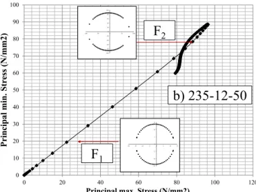
Figure 13 shows a plot displaying the evolution of the maximum and minimum principal stresses at point j of the AP. This point (located on the neutral axis) is expected to undergo pure shear and consequently, the associated Mohr’s circle is centered in the origin.
Figure 13(a) displays the evolution of the principal stresses in a slender prototype. Initially, a
linear relationship between minimum and maximum principal stresses is observed (up to F1). The
associated Mohr’s circle is centered in the origin. As the load increases, the minimum principal stress vanishes (since the web buckles and is unable to carry compressive stresses) and the tension field action develops. The associated Mohr’s circle moves rightwards with no noticeable compres-sive stresses.
0
1 2 3 4 5 6 7
8
9 10 11 12
0 50 100 150 200 250 300
F1
/F
c
r
hw/tw
F1/Fcr,M1
F1/Fcr,M3
0 5 10 15 20 25 30
0 50 100 150 200 250 300
F2
/F
c
r
hw/tw
F2/Fcr,M1
Latin American Journal of Solids and Structures 11 (2014) 1721-1743
Figure 13(b) displays the evolution of the principal stresses in a stocky. A linear relationship
be-tween minimum and maximum principal stresses is observed up to F2. The associated Mohr’s circle
is centered in the origin during loading. Since the web does not undergo shear buckling, the pure shear stress state is maintained.
tw=3mm tw=4mm tw=6mm
tw=8mm tw=10mm tw=12mm
Figure 12: Failure modes observed for girders of the series 235-i-50 with i=[3,4,6,8,10,12].
Figure 13a. 0
5 10 15 20 25 30 35
0 50 100 150 200 250 300
P
ri
n
ci
p
al
mi
n
.
S
tr
es
s
(N
/m
m2)
Principal max. Stress (N/mm2)
F
2 -15-10 -5 0 5 10 15
-20 -15 -10 -5 0 5 10 15
-150 -100 -50 0 50 100 150
0 50 100 150 200 250 300
Latin American Journal of Solids and Structures 11 (2014) 1721-1743
Figure 13: Principal stresses evolution for two girders at point j a) 235-3-50 b) 235-12-50.
5.2.2 Influence of the transverse stiffeners on the ultimate load
Figure 14 displays the maximum load capacity F2 for all girders as a function of the transverse
stiffener thickness ts. The plots are separated for different web slenderness and varying flange yield
strength. From these plots, a set of conclusions can be pointed out:
• For slender girders (in which noticeable shear-patch loading interaction is observed), the
transverse stiffener rigidity plays a considerable role. The higher the value of ts, the higher
the ultimate load capacity. For some cases, the ultimate load capacity for a girder with rig-id stiffeners double the capacity of the girder with flexible members.
• For stocky girders, the transverse stiffener rigidity plays a less considerable role. High
val-ues of ts lead to higher values of ultimate load capacity the observed increments do not
sur-pass 30% between flexible and rigid stiffeners.
0 10 20 30 40 50 60 70 80 90 100
0 20 40 60 80 100 120
P ri n ci p al mi n . S tr es s (N /m m2)
Principal max. Stress (N/mm2)
F
2F
1 -15 -10 -5 0 5 10 15-20 -15 -10 -5 0 5 10 15 -100 -80 -60 -40 -20 0 20 40 60 80 100
-100 -50 0 50 100
b) 235-12-50
0 500 1000 1500 2000 2500 3000 35000 20 40 60
M a x im u m l o a d (k N )
ts(mm)
S460 S355 S235
hw/tw=250
0 500 1000 1500 2000 2500 3000 3500
0 20 40 60
M a x im u m l o a d (k N ) t (mm) S460 S355 S235
Latin American Journal of Solids and Structures 11 (2014) 1721-1743
Figure 14: F2 vs. ts.
The primary role played by the transverse stiffeners is related to the anchoring capacity provided to the web panel. Rigid elements allow to the web panel to fully develop the DLP four hinge mecha-nism and (for some cases) the tension field action at AP. Flexible elements buckle prematurely at both DLP and AP and are unable to provide a sufficiently rigid line. Figure 15 illustrates these observations for slender webs (noticeable shear-patch loading interaction) and for stocky web panels (failure at DLP as primary mode). In design, stiffeners are used to provided rigid non-deformable lines. It is, thus, rather infrequent to provide flexible stiffeners to plated structures.
460-3-8 460-3-50
0 500 1000 1500 2000 2500 3000 3500 4000
0 20 40 60
M a x im u m l o a d (k N ) t (mm) S460 S355 S235
hw/tw=125
0 500 1000 1500 2000 2500 3000 3500 4000
0 20 40 60
M a x im u m l o a d (k N )
ts(mm) S460
S355
S235 hw/tw=93,75
0 500 1000 1500 2000 2500 3000 3500 4000 4500 5000
0 20 40 60
M a x im u m l o a d (k N )
ts(mm) S460
S355
S235 hw/tw=75
0 500 1000 1500 2000 2500 3000 3500 4000 4500 5000
0 20 40 60
M a x im u m l o a d (k N )
ts(mm)
S460 S355 S235
Latin American Journal of Solids and Structures 11 (2014) 1721-1743
460-12-8 460-12-50
5.2.3 Influence of the flange yield strength on the ultimate load capacity
Figure 15 shows P-δ plots for slender girders (a) and stocky girders (b) with varying values of fyf. .
In both cases, the girders are assembled with rigid transverse stiffeners (ts=50 mm). The following
remarks are worth pointing out:
• All plots present an initial linear relationship.
• For both cases (slender and stocky specimens), the loss of linearity (F1) occurs at the same
point for all values of fyf.
• For slender girders, increasing the value of fyf increases the value of F2 but this increment
is not proportional. It is observed that the existing difference between S235 and S355 is far greater than the observed difference between S355 and S460. This behavior is due to the se-vere shear-patch loading interaction existing in this particular girder that undermines the development of the four plastic hinges at the DLP.
• For stocky girders, increasing the value of fyf increases the value of F2 quite proportionally.
Latin American Journal of Solids and Structures 11 (2014) 1721-1743
Figure 16:P-δ plots for hw/tw=250 (a) and hw/tw=62,50 (b).
It is confirmed that the flange yield strength plays a primary role in the post-F1 capacity (ΔFf) but
this capacity may not be fully achieved in very slender specimens where shear-patch loading inter-action occurs. The mechanical observations suggest that four plastic hinges form in the flange at the DLP. Two hinges form at the flange-to-stiffener juncture and two other precisely below the applied load (forming both hogging and sagging zones).
It is worth pointing out that one key aspect that defines the value of ΔFf is the flange yield
reserve at F1. At this value, due to bending, both top and bottom flanges are longitudinally stressed
a certain value σF1. The flange yield strength reserve is then defined as (1-σF1/fyf)· fyf, where σF1 is
the flange longitudinal stress at F1 at the location of each plastic hinge. If σF1 approaches zero, the
flange yield reserve is practically equal to fyf. If σF1 approaches fyf, the flange yield reserve is
practi-cally equal to zero. Previous works presented by Chacón et al (2013a, 2013b) show further details
concerning this topic from the design perspective and design formulae are provided.
Finally, figure 16 displays the ratio ΔFf/F2, which quantifies the percentage of the total load
bearing capacity provided by the flanges. The results are plotted against the flange yield strength for different values of web slenderness and fixed transverse stiffener rigidity. From this plot, several conclusions are pointed out:
• The flange relative contribution increases with the web slenderness. Slender web panels
develop post-critical resistance mechanisms that anchor in the flanges, which provide con-siderable additional bearing load. Stocky web panels provide a concon-siderable contribution to the ultimate load, and the anchoring mechanisms that form present a relatively low contri-bution.
• For slender girders, as the flange relative contribution is high, increasing the flange yield
strength leads to an increase of the ratio ΔFf/F2. This trend is, however, limited in
speci-mens with high shear-patch loading interaction.
0 500 1000 1500 2000 2500 3000 3500 4000 4500 5000
0 10 20 30 40 50
Loa
d
(
k
N
)
Out-of-plane displacement point i (mm) S235
S355
S460
0 500 1000 1500 2000 2500 3000 3500 4000 4500 5000
0 10 20 30 40 50
Loa
d
(
k
N
)
Out-of-plane displacement point i (mm) S235
S355
Latin American Journal of Solids and Structures 11 (2014) 1721-1743
• For girders with moderate slenderness and low web slenderness, the ΔFf/F2-fyf trend is
linear and full development of the flange capacity is developed.
Figure 16:ΔFf / F2 vs. fyf.
6 CONCLUSIONS
The mechanical behavior of steel plate girders subjected to patch loading with susceptibility to
shear buckling is studied throughout a numerical parametric study. P-δ plots, ultimate load
capaci-ties and visual renders are systematically used for the sake of studying the overall behavior of the girders when subjected to a monotonic increasing loading process up to failure. From the presented observations several remarks are worth pointing out.
• The susceptibility to shear-patch loading interaction in transversely stiffened steel plate
girders loaded over unstiffened sections is defined by the web slenderness. This susceptibil-ity may be quantified by using the ratios between elastic critical buckling loads as well as
the ratios between F1 (the load at which the loaded panel fails) and the adjacent panel
elas-tic crielas-tical buckling loads.
• The girders with no susceptibility to shear-patch loading interaction fail following a four
hinges mechanisms at the directly loaded panel (DLP) and severe web folding whereas gird-ers in which the interaction has been observed fail with an intertwined mechanism of four-hinges at the DLP with severe web folding as well as the formation of the tension field ac-tion on the adjacent panels (AP).
• Flexible stiffeners do not provide sufficient rigidity to the web panels for developing
an-choring capacities either for patch loading at DLP or shear buckling at AP. Increasing the stiffener thickness leads to higher ultimate loads with a particular high gain in slender gird-ers.
• The flange yield strength plays a primary role in the development of post-F1 capacity. The
flange contribution is particularly high in slender web panels whereas relatively low for
0,00 0,10 0,20 0,30 0,40 0,50 0,60 0,70
200 250 300 350 400 450 500
Δ
Ff
/ F
2
fyf
hw/tw=250 hw/tw=187,5 hw/tw=125 hw/tw=93,75 hw/tw=75 hw/tw=62,5
Latin American Journal of Solids and Structures 11 (2014) 1721-1743
stocky panels, in which the web provides a considerable contribution to the ultimate load
capacity of the girders.
References
AASHTO (USA) (2009). LFRD Bridge Specification Abaqus-Simulia v. 6.10 (2013). Dassault Systèmes.
Azizinamini A., Hash J., Yakel A., Farimani R. (2007). Shear capacity of hybrid plate girders. Journal of Bridge Engineering. Vol. 12 (5) 535-543.
Barker M., Hurst A., White D. (2002).Tension Field Action in Hybrid Steel Girders. Engineering Journal, AISC, Vol. 39(1) 52-62.
Basler, K.(1961). Strength of Plate Girders in Shear. Journal of Structural Division, ASCE, 87(7), 151-180.
Bedynek A. ,Real E. ,Mirambell E. (2013). Tapered plate girders under shear: Tests and numerical research. Engi-neering Structures, Vol.46 (1) 350–358.
Beg D., Kuhlmann U., Davaine L., Braun B. (2012). Design of Plated Structures: Eurocode 3: Design of Steel Struc-tures, Part 1-5: Ernst & Sohn (Berlin).
Chacón R., Mirambell E., Real E. (2013a). Transversally stiffened plate girders subjected to patch loading. Part 1. Preliminary study. Journal of Constructional Steel Research, Vol 80 (1) 483-491.
Chacón R., Mirambell E., Real E. (2013b). Transversally stiffened plate girders subjected to patch loading. Part 2. Additional numerical study and design proposal. Journal of Constructional Steel Research, Vol 80 (1) 492-504. Chacón R., Mirambell E., Real E. (2010). Hybrid steel plate girders subjected to patch loading, Part 2: Design pro-posal. Journal of Constructional Steel Research, Vol 66 (5) 709-715.
Dowling P., Harding J., Bjorhovde R., (1992). Constructional Steel Design. An international guide, Elsevier applied science (London and New York).
Dubas P., Gehri E. (1986). Behaviour and design of steel plated structures, ECCS-CECM-EKS (Zurich).
Duerr D. Beam web strength under pairs of concentrated compression loads. (2003). Practice periodical on structural design and construction, Vol 8(1), 25-30
Elgaaly M. (1983). Web design under Compressive Edge loads. Engineering Journal. Vol. 20(4) 153-171
Eldib M. (2009). Shear buckling strength and design of curved corrugated steel webs for bridges. Journal of Con-structional Steel Research. Vol. 65(12), 2129-2139.
EN1993-1-5. Eurocode 3. Design of steel structures – Part 1-5: Plated structural elements CEN. 2006
Galambos T. (1998). Guide to Stability design criteria for metal structures, John Wiley and sons (New York). Graciano C., (2003). Ultimate resistance of longitudinally stiffened webs subjected to patch loading. Thin-Walled Structures. Vol. 41(6), 529-541
Höglund, T. (1971). Simply supported long thin plate I-girders without web stiffeners subjected to distributed trans-verse load. IABSE Colloquium London, Reports of the Working Comissions, Vol 11, 85-97.
Lagerqvist O., Johansson B. (1996). Resistance of I-girders to concentrated loads. Journal of Constructional Steel Research, Vol. 39 (1), 87 – 119
Markovic N. Hajdin N. (1992). A contribution to the analysis of the behaviour of plate girders subjected to patch loading. Journal of Constructional Steel Research. Vol. 21,163 – 173
Latin American Journal of Solids and Structures 11 (2014) 1721-1743 Real E., Estrada I., Mirambell E.(2007). Shear response of stainless steel plate girders. Engineering Structures. Vol. 29(7), 1626-1640.
Roberts T., Rockey K. (1979). A mechanism solution for predicting the collapse loads of slender plate girders when subjected to in-plane patch loading. Proceedings of the Institution of Civil Engineers, Part 2, 67, pp. 155 – 175. Rockey, K., Skaloud, M. (1972). The Ultimate Load Behaviour of Plated Girders Loaded in Shear. The Structural Engineer, Vol. 50 (1), 29-47
Šćepanović B., Gil-Martín L., Hernandez-Montes E., Aschheim M., D. Lučić D. Ultimate strength of I-girders under


![Figure 12: Failure modes observed for girders of the series 235-i-50 with i=[3,4,6,8,10,12]](https://thumb-eu.123doks.com/thumbv2/123dok_br/18885120.423647/16.807.162.691.213.556/figure-failure-modes-observed-girders-series-i-i.webp)