R
e
v
isã
o
*e-mail: [email protected]
ELECTROCHEMISTRY AND GREEN CHEMICAL PROCESSES: ELECTROCHEMICAL OZONE PRODUCTION
Leonardo M. da Silva e Mário H. P. Santana
Departamento de Química, Faculdade de Filosofia Ciências e Letras de Ribeirão Preto, Universidade de São Paulo, Av. Bandeirantes 3900, 14040-901 Ribeirão Preto - SP
Julien F. C. Boodts*
Instituto de Química, Universidade Federal de Uberlândia, Campus Santa Mônica, Av. João Naves de Ávila 2160, 38400-902 Uberlândia - MG
Recebido em 25/11/02; aceito em 1/4/03
After an introductory discussion emphasising the importance of electrochemistry for the so-called Green Chemical Processes, the article presents a short discussion of the classical ozone generation technologies. Next a revision of the electrochemical ozone production technology focusing on such aspects as: fundamentals, latest advances, advantages and limitations of this technology is presented. Recent results about fundamentals of electrochemical ozone production obtained in our laboratory, using different electrode materials (e.g. boron doped diamond electrodes, lead dioxide and DSA-based electrodes) also are presented. Different chemical processes of interest to the solution of environmental problems involving ozone are discussed.
Keywords: ozone; electrochemistry; environment; green processes.
INTRODUCTION
Modern chemistry plays a key role in the improvement of quality of life around the world. However, these advances frequently came with an increase in contamination of the environment by toxic substances. Nowadays steps are being taken, mainly due to increasing economic, social, legal, and environmental pressures, to avoid further degradation. Therefore, the use of the so-called Green Chemical Processes where the “best available technology” not entailing excessive cost and aspiring to “performance without pollution” can be used in industrial processes is stimulated1. We are now seeing
momentum building around the green theme, where green products, processes, and technologies are deemed good for mankind. In this context, catalysis has and will continue to impact the discovery and development of environmentally attractive technologies and products2.
As discussed in some contributions published in the IUPAC special topic issue, entirely dedicated to Electrochemistry and Interfacial Chemistry for the Environment3-9, electrochemical
technology has an important role to play as part of an integrated approach to the avoidance and monitoring of pollution, process efficiency, cleaner processing, and modern techniques for electrical energy storage and conversion.
A fundamental reason for the importance of the electrochemical technology to minimise environmental problems is that it uses electricity as energy source. Of course, one must remember that when generated burning fossil components (e.g. coal, oil) a certain degree of environment contamination takes place mainly as CO2 injected in the atmosphere. However, with respect to this issue, Brazil presents a more favourable situation since most of its electrical energy is generated in hydroelectric plants (although even this technology is not totally environmentally friendly).
Electrochemical technology can be used directly in several applications involving the removal and degradation of potential solid
and liquid pollutants from industrial wastes in water, soil and atmosphere10. Besides, this technology can also be used in the
generation of very active oxidant species with proven efficiency in several green processes.
An environmental friendly oxidant should posses the following features11: (i) reactive with compounds to be treated; (ii) neither
produce nor leave undesirable by-products during the course of the reaction and (iii) readily available. A number of chemical oxidants are currently being used either as disinfectants for potable or swimming pool waters, or for the destruction of organic and inorganic chemical species found in wastewater. The most commonly used oxidants for the above purposes are: ozone, hydrogen peroxide, chlorine, chlorine dioxide, sodium and calcium hypochlorite, and potassium permanganate.
The benefits of generating oxidants electrochemically include11:
(i) close control of product yield and purity through control of applied current; (ii) elimination or minimisation of chemical by-product generation during oxidant synthesis; (iii) transport and storage of toxic and hazardous oxidants can be eliminated by producing them on site at an amount proportional to the waste concentration and (iv) electrochemical processes could have an economic advantage over traditional routes for oxidant generation, especially in small scale uses. In particular, applications involving ozone have a number of advantages: it is a very strong oxidant (Eo = 1.51V(vs. RHE)); its
decomposition leads to environmental friendly products (O2); its instability (t½ = 20-90 min, depending on environment) requires it to be produced “on spot” reducing expenses and danger with transportation and storage. Ozone finds application in fields such as: water treatment, combustion of resistant organics, clean-up of effluents, bleaching of wood pulp2,10,11.
Chlorine has long been used in the disinfection of water. It now seems that chlorinated hydrocarbons formed during the treatment may posses some carcinogenic action12. For this reason chlorine is
being replaced by ozone or hydrogen peroxide, whose production must thus be increased and improved. In the particular case of pulp and paper bleaching13, there is an increasing demand for alternatives
dioxide by ozone as a bleaching agent permitted the development of the so-called totally chlorine free (TCF) bleaching technology14,
reducing significantly the pollution burden and potential health hazard of chlorine derivatives of this industrial activity.
Several aspects related to ozone production and its applications were discussed in the 80’s by Rice and Netzer15. Nowadays, ozone
being an environmentally clean reagent with proven efficiency for several processes of technological importance, a crescent interest in electrochemical ozone production is observed16-44.
The objective of this article is to revise and discuss fundamentals aspects as well applications of ozone production, giving especial attention to its electrochemical production. Green Chemical Proces-ses where ozone can be employed are also discussed.
Ozone
According to Rideal45, reports about ozone can be traced back to
1785 when van Marum, a Dutch physicist, found electric discharge in the air results in a characteristic ozone odour. In 1801 the same odour was observed during water electrolysis45. However, ozone
discovery was only officially announced by Schönbein46, at the
Academy of Munich, in 1840. The name “ozone” was derived by Schönbein from the Greek word “ozein”, meaning “to smell”.
In 1845 de la Rive and Marignac47 obtained ozone by submitting
pure dry oxygen to an electric spark. Later, investigations conduced by Hunt48 on the oxidant properties of ozone permitted the author to
postulate the ozone molecule is tri-atomic oxygen. Figure 1 shows the structure of the ozone molecule described by Bailey49 as a
resonance hybrid of the four canonical forms.
As shown in Figure 1 ozone, O3, is a triangular shaped molecule. Under ambient conditions it is an unstable gas possessing a very strong oxidation power and a characteristic sweet odour which is detectable in air (e.g. near copier machines) by most people at a concentration as low as 0.01ppm50. Under normal conditions of
temperature and pressure O3 is moderately soluble in water (about 13 times higher than O2). Its decomposition rate, producing O2, strongly depends on the purity of the solvent phase, decreasing in the presence of impurities51. Ozone is the second most powerful
oxidant molecule, exceeded in its oxidising power only by fluorine. Since ozone is a non-polluting oxidant (ozone is reduced to oxygen during oxidation of organics), its use far exceeds that of fluorine. In the mid 70’s, ozone received a considerable amount of attention after it was shown that hydroxyl radicals are formed in ozonated water in the presence of either ultraviolet light, UV, or hydrogen peroxide11.
These hydroxyl radicals are oxidising agents52 far more powerful
than ozone itself.
Ozone production using electric discharge and UV-absorption
Ozone production by the corona discharge technology
The most important progress in ozone production was obtained by von Siemens53 in 1857, when he developed an ozone generator
tube based on the corona discharge process. Such process is based on the application of an alternating voltage between two electrodes
with dry air or oxygen passing in between. As a result of the electrical discharge, oxygen molecules decompose in O• which combines with
O2 resulting in O3-formation. In the prototype developed by von Siemens about 3-8% of oxygen was converted to ozone. This type of ozone generator has subsequently served as a prototype for the majority of electric discharge generators54.
Advances in the corona technology were obtained as a result of the investigation of the influence of the gas phase (oxygen) temperature on ozone yield54. This study revealed an increase in O
3
-concentration with decreasing temperature.
O3 production in the corona technology can be described by next mechanism55:
e-1 + O 2 → 2O
• + e-1 (1)
O• + O
2 + M → O3 + M* (2)
where M represents a molecule of an activated inert gas (e.g. N2) serving the propose of removing the excess energy acquired during ozone molecule formation.
As shown by the above mechanism the reaction initiates when free electrons, having high energy (e-1), collide with an oxygen
molecule resulting in its dissociation. In the next step ozone is formed by a third order collision. As a result of energy absorption during collision the inert gas molecule turns into an excited molecule, M*. The importance for O3 production of the activated inert gas inside the corona device was verified by Popovich et al.56. Cromwell and
Manley57 and Rosen58 showed O
3 production increases about 2-7%
by adding 5 to 8 vol% of N2 to the gas phase.
Simultaneously with ozone production a parallel route for ozone decomposition takes place when atomic oxygen or energised electrons react with an ozone molecule according to the following mechanism55:
O• + O
3 → 2O2 (3)
e-1 + O
3 → O2 + O
• + e-1 (4)
So, according to the above mechanisms, corona efficiency for O3 production is the result of competition between steps (1)-(2) and (3)-(4). Literature data54 show experimental factors affecting the
corona efficiency for O3 production are: temperature of the entering gas, oxygen content, presence of contaminants in the gas phase, ozone concentration, electric power and the gas flow.
The output from a modern corona-discharge system has been report to vary from 2 wt% for air as the input gas to 7 wt% for oxygen as the input gas59. This low O
3-concentration is the main
drawback presented by the corona technology. The specific energy consumption of classical ozonizers reported in the literature16 is
around 14 Wh g-1 for air and 6 Wh g-1 for oxygen feed. However, a
more recent study60 reports a value of 5 Wh g-1 for air.
Literature data61 show the use of corona technology in reactor
systems for ozonation of organics in water can be optimised by: (i) reducing the amount of energy input and (ii) increasing the mass transfer rate of ozone gas into the aqueous phase. While the former depends on geometry of the corona, the latter depends on the mixing characteristics of the gas-liquid contactor used, the kinetics of ozone decay in water, and the number and size of bubbles produced. Optimisation of these parameters for different ozonation systems has been reported in the last ten years60-64. Suarasan et al.60 presented an
AC corona ozonation system using multi-point high-voltage electrodes as a means for direct ozonation of liquids. Shin et al.61
proposed an ozonation system which produces micro-bubbles having an average bubble diameter of 1.34-5.0x10⁻² mm. An increase of up
to 40% in mass transfer rate was observed by these authors. The production of active species such as OH•, H
2O2, and O3 in water and
aqueous solution has also been studied using the so-called pulsed-streamer corona discharge62. A combination of air stripping and pulsed
corona has also been tested63. Goheen et al.64 report ozone generation
in devices where a DC corona discharge is created between an electrode and the surface of a liquid.
Attempts have also been made to use advanced oxidation pro-cesses (AOP’s)65, such as the combination of ultraviolet (UV) light
or hydrogen peroxide (H2O2) with standard corona ozonation systems, in order to increase the amount of hydroxyl radical (OH•), thus
reducing the O3-demand.
Photochemical ozone production
When irradiated by UV-light the O2-molecule absorbs electro-magnetic energy and can dissociate in two oxygen atoms. The oxygen atom can then combine with a neighbour O2 molecule producing a ozone molecule, O3.
Theoretically, the quantum yield of ozone production by irradiation of light at wavelengths, λ, shorter than 242 nm is 2.0, since each photon absorbed by an oxygen molecule will produce two oxygen atoms, each of which, in principle, can produce one ozone molecule66:
O2 + hν → 2O• (5)
O• + O
2 → O3 (6)
However, the experimentally observed quantum yield is always lower than 2.0, in part, due to the reaction66:
O3 + O• → 2O
2 (7)
and, in part, to the photolysis of ozone by electromagnetic energy absorption67:
O3 + hν → O2 + O•(1D) 200 ≤ λ ≤ 308 nm (8)
where O•(1D) represents the excited electronic state of the oxygen
atom called singlet.
The photochemical process requiring the least amount of energy will produce oxygen atoms in their lower energy statefollowing next process68:
O2 (3Σ– g) → 2O
•(1P) ∆H = 118 Kcal mol-1 (9)
where O2 (3Σ–
g) represents the ground state of the oxygen molecule
and O•(1P) represents the electronic state of oxygen atom called triplet.
The energy involved in the above mentioned process corresponds to a wavelength of 242 nm. In practice it is very difficult to produce light of the appropriate wavelength (λ ≅ 242 nm) to produce ozone from oxygen without the simultaneous presence of the longer and shorter wavelengths where ozone photolyses takes place (200 ≤ λ ≤ 308 nm) (see eq.8). Therefore, the experimentally observed quantum yield of ozone production is a balance between the yield of production (see steps 5 and 6) and the photolysis yield (see step 8). This balance obviously depends on the ratio of producing to ozone-consuming wavelengths present.
As already mentioned for the corona technology (see previous discussion), another factor affecting quantum yield of ozone formation is the presence of an inert body. Such process is represented as follows:
O• + O
2 + M → O3 + M* (10)
where M is any inert body present, such as: reactor wall, a nitrogen
molecule or a molecule of carbon dioxide. M acts removing the energy excess acquired during ozone molecule formation resulting in an excited inert body, M*. Literature data show69 the relative yields of
ozone production at 185 nm, using as UV-source a low pressure mercury lamp at 1 atm total pressure and 0.25 atm of oxygen pressure, varies according to the inert gas used (e.g. CO2, N2, Ar) presenting values in the 0.5-1.0 interval. Calculations69 show the ozone
production rate achieved using a low-pressure mercury lamp (λ = 185 nm), considering 37% of the available UV-radiation is absorbed by oxygen to produce ozone, is 0.72 g kWh-1. This production rate
can be improved if the photochemical reactor wall is made of, or is coated with, a reflective material, such as polished aluminium.
Compared with the corona process (discussed in the previous section) photochemical ozone production is not a very efficient means of producing large amounts of ozone. However, UV-light is very suitable for producing ozone in small amounts e.g. for laboratories proposes, odour elimination, etc. A great attractive of photochemical ozone production is reproducibility due to the easy control of the rate of ozone production by controlling lamp source power.
Hybrid ozonation systems based on the combination of corona discharge technology combined with the simultaneous exposure of wastewater to UV-radiation has been developed for a variety of purposes, for instance, the destruction of polychlorinated biphenyls (PCB)70 and phenol61.
Ozone production from water electrolysis
The low ozone concentration available using electric discharge in the gaseous phase (corona process) or UV-light absorption (photochemical process) technologies restricts ozone application in several Green Chemical Processes where a higher O3-concetration is necessary11,71 (e.g. decomposition of resistant organic pollutants). To
circumvent this difficulty various electrochemical processes for ozone production from water electrolysis were and are being investigated11,
originating the electrochemical technology called here electrochemical ozone production, EOP. The EOP-technology can generate far higher ozone concentrations than available conventionally40, making possible the combustion of several resistant
organic pollutants.
Stucki et al.34 showed an electrochemical reactor for EOP can
furnish optimum current yields in the order of 20% with a specific power consumption in the order of 65 Wh g-1. Considering the
technology available in the 80’s, Foller and Goodwin72 concluded at
that time EOP has “economic advantages” for ozone production rates less than 6.8 kg day-1. Great advances have been made in EOP in the
90’s using air depolarised cathodes in the electrochemical reactor40.
Nowadays the rigid environmental legislation requiring the adoption of Green Chemical Processes has changed this unilateral point of view and strongly disregards economical aspects as a major limitation for the implantation of this technology which can significantly contribute to environment conservation.
Fundamentals of electrochemical ozone production
During electrolytic decomposition of water ozone is formed in the anodic compartment of the electrolytic cell according to the following half cell reaction71:
O3 + 6H+ + 6e- → 3H
2O E
o = 1.51V(vs. RHE) (11)
Oxidation of evolved oxygen could also possibly produce ozone according to:
O3 + 2H+ + 2e- → H
2O + O2 E
However, up-to-now from a practical point of view only the process represented by eq.11 has been considered in the literature4,16,17,34,71.
The oxygen evolution reaction, OER, always occurs simultaneously during EOP since it occurs preferentially over EOP due to its lower standard potential71:
O2 + 4H+ + 4e- → 2H
2O E
o = 1.23 V(vs. RHE) (13)
As discussed recently by Da Silva et al.4,43, although OER is a
parallel reaction, this apparently “undesirable” process is necessary for EOP. Such argument is based on kinetic considerations since the partial coverage by adsorbed O2-molecule of the electrode surface acting as an intermediate for EOP directly affects the current efficiency of EOP (fraction of the current leading to ozone production). So, optimisation of EOP performance by a given electrode/electrolyte combination, is governed by partial inhibition of the OER and the formation of a more adequate O2 and O•-coverage of the electrode
surface4,43.
Three basic requirements for EOP are: (i) electrode material should present good conductance and a high anodic overpotential for OER; (ii) anions and cations from electrolyte should not engage in competitive reactions with OER/EOP and hydrogen evolution reaction, HER, respectively, and (iii) to avoid/minimise electrode wear, electrode material should present its highest oxidation state or be kinetically resistant to further oxidation.
The above considerations strongly restring candidates for electrode material and electrolyte. Literature data4,11,15-44 show most
EOP investigations made use of Pt, glassy carbon, boron doped-diamond, PbO2 and PbO2/Ebonex (Ebonex is a commercial material based on titanium suboxides) as electrode materials and H2SO4, HClO4 or H3PO4 solutions as electrolyte.
Different electrode mechanisms to describe the OER/EOP pro-cesses, taking into account different intermediates, can be found in the literature30,36,73. However, these mechanisms do not permit a direct
correlation between kinetic, surface adsorbed species and current efficiency for EOP. Recently Da Silva et al.4 proposed the following
electrode mechanism for OER/EOP processes at inert electrodes (e.g. β-PbO2), which permits a correlation between current efficiency for EOP and surface coverage by oxygen intermediates.
Kinetic studies based on Tafel slope determination, b(≡ (ME/ Mlog j)
T) support primary water discharge (step (a)) as rate determining (rds) for the OER/EOP processes4,43,74-76. In the above mechanism
EOP occurs at high overpotentials (E > 1.51 V(vs. RHE)), via steps (g) and (h), simultaneously with OER via step (f), respectively. Initially the electrochemical reaction proceeds via “electrochemical steps” (steps (a) and (b)) where the anodic current is sustained by the oxidation of the adsorbed water molecule, with concomitant release of two H+ ions, resulting in an electrode surface covered by O• having
a very low interfacial pH. Continuation of the electrode process proceeds via “chemical steps”, which control the efficiency with respect to EOP and OER processes by means of a combination of the adsorbed intermediate species on the electrode surface (for more details see refs. 4 and 43). As demonstrated by Da Silva et al.4 the
current efficiencies with respect to OER , ΦOER, and EOP, ΦEOP, pro-cesses are a function of the θ and β coverage according to:
ΦOER = [1-β]×[1-θ] (14)
ΦEOP = [θ+β(1-θ)] (15)
Theoretical calculations4 show maximum Φ
EOP is obtained for θ
and β-values tending towards unity. Under these conditions ozone formation (steps (g) and (h)) is favoured over oxygen evolution (step (f)). Accordingly, under these conditions OER is minimum, serving only as a source of adsorbed O2-species necessary for ozone formation at the electrode surface.
Eqs.14 and 15 clearly show that any experimental conditions optimising the partial coverages θ and β result in a direct improvement of the electrode performance for EOP.
Advances achieved in the electrochemical ozone production in the last decades
Since the discovery of ozone by electrolysis of sulphuric acid solutions in 1840 by Schönbein46 approximately 25 publications have
appeared until the 80’s dealing with its electrolytic generation. During this long period technological progresses and profit prevailed over environmental concerns, causing an inhibition of the research involving EOP due to the costs related with this technology. However, as shown by the literature4,15-44 in the last decade rigid environmental
legislation requiring as soon as possible the adoption of Green Chemical Processes has re-opened this prominent technological field. Initially the first systematic studies involving ozone production from water electrolysis were conduced using platinum as electrode material and sulphuric acid solutions as supporting electrolyte. The use of a noble metal such as platinum in EOP studies is due to its high overpotential for the OER associated with its inertia during electrolysis even under drastic conditions of current density and interfacial potential.
The platinum/sulphuric acid system was exploited in two different ways: (i) using sulphuric acid solutions77,78 and current densities
ranging between 50-100A cm-2Φ
EOP-values of up to 27% were
obtained at 0 oC; (ii) employing eutectic electrolyte compositions
and very low temperatures (<< 0 oC) Φ
EOP-values of up to 32% were
reported79,80. Literature data81,82 also report the use of a platinum anode/
perchloric acid combination showing a ΦEOP yield of 36% at -40 oC.
A significant advance in the EOP technology came with the use of PbO2 as anode. The studies were conduced by three different groups of researchers: Semchenko et al.83-85; Fritz et al.86 and Foller and
Tobias17,18,39,40,72.
For several reasons PbO2 in its two crystallographic forms (α and β) is a very convenient electrode material for EOP: (i) it is rather cheap; (ii) supports high current densities without considerable wear; Mechanism for oxygen/ozone production at inert electrodes
Electrochemical steps: Kinetic control (H2O)ads → (OH•)
ads + H
+ + e- rds (a)
(OH•) ads → (O
•) ads + H
+ + e- (b)
Chemical steps: Efficiency control (O•)
ads → [1-θ](O •)
ads + θ(O •)*
ads, (0 < θ < 1) (c)
[1-θ](2O•)
ads→ [1-θ](O2)ads (d)
[1-θ](O2)ads → [1-β]×[1-θ](O2)ads + β[1-θ](O2)*ads (0 < β < 1) (e)
Oxygen evolution:
[1-β]×[1-θ](O2)ads→ O2↑ (f)
Ozone formation: θ(O•)*
ads + β[1-θ](O2)*ads → [θ+β(1-θ)](O3)ads (g)
[θ+β(1-θ)](O3)ads→ O3↑ (h)
(iii) presents ΦEOP-values higher than those obtained at Pt electrodes for the same conditions of electrolyte and temperature.
Initially Semchenko et al.83-85 studied the electrolysis of
phos-phoric and perchloric acid reporting ΦEOP-values of 13% (10-15 oC)
and 32% (-15 oC), respectively. These authors observed an increase
in ΦEOP as a result of adding small quantities of fluoride ion to the electrolyte. Problems related with PbO2 wear during EOP were observed by Semchenko et al.83-85 at that time. Foller and Tobias17
proposed PbO2 wear is a result of a chemical/electrochemical dissolution mechanism operating under strong acid conditions. This inconvenient process was overcome by Kötz and Stucki16,34 a few
years later. These authors observed that the introduction of a solid polymer electrolyte membrane (spe) separating anode from cathode avoids the use of conventional acid electrolytes thus reducing significantly PbO2 wear.
In the 70’s, Fritz et al.86 investigated phosphoric acid-based
electrolyte systems reporting ΦEOP-values of up to 13% at ambient temperatures. These authors also observed PbO2 wear is suppressed in neutral buffered electrolyte.
Considerable advances in the EOP technology were obtained by Foller and Tobias17,18,40 investigating the influence of the addition of
several different fluoro-anions to the electrolyte (e.g. F-, BF 4
-, PF 6
-).
These authors reported ΦEOP-values of up to 53%, at β-PbO2 electrodes at 0 oC, in 7.3 mol dm-3 HPF
6. Fundamental studies conduced by
Foller and Tobias17 using as anode Pt and PbO
2 and different
fluoro-anions containing electrolytes, revealed a correlation between anion surface adsorption and ΦEOP. Studies37,38 of EOP conduced in the 90’s
show the introduction of different ions, including fluoride anion, as doping agent into the PbO2 coating also affects the ΦEOP.
The use of glassy carbon as electrode material for EOP was investigated by Foller and Tobias72. These authors found pressed
carbon black rapidly degrades while exhibiting CO2 evolution as side reaction. Conventional graphite also undergoes wear during EOP as a result of c-axis swelling provoked by anion intercalation between its planes.
Advances in the fundamentals of EOP were recently achieved in our laboratory by Da Silva et al.4 when these authors showed that
besides the nature of the electrode material, electrode morphology (e.g. porosity, roughness) also strongly influences EOP kinetics and ΦEOP. On β-PbO2 electrodes, depending on electrode morphology, BF4- can both act increasing or inhibiting EOP. Advances on the
kinetics for EOP were also achieved4,36,73. The electrode mechanism
recently proposed by Da Silva et al.4 for OER/EOP processes at inert
electrodes permits an adequate theoretical interpretation of the influence on ΦEOP of the stability of intermediate oxygenated species adsorbed on the electrode surface (see previous discussion). In a recent study conduced by Da Silva et al.43, involving the determination of
the activation energy for both the OER and EOP processes it was shown that the presence of fluoro-anions in the electrolyte affects EOP indirectly by inhibiting the OER process in the high overpotential domain.
EOP studies at boron doped-diamond electrodes, BDDE, were also reported in the literature27,33. This material presents a very high
overpotential for OER associated with a high corrosion resistance. Considerable ΦEOP-values in acid medium were found. A revision about conductive diamond electrodes and its application to electrochemical processes was recently published by Pleskov87.
Factors affecting ΦΦΦΦΦEOP
The main factors affecting EOP are: (i) chemical nature of the electrode material; (ii) electrode morphology; (iii) chemical nature of the electrolyte; (iv) current density; and (v) temperature of the
electrolyte. Therefore, to clarify the influence of these parameters on ΦEOP we here present some contributions from our laboratory obtained in the last two years.
EOP current efficiency data presented in the following discussions were calculated according to the following equation4,43:
ΦEOP/% = [(A.Vo.z.F)/(ε.l.IT)].100 (16)
where: A = Absorbance at 254 nm; Vo= volumetric flow rate of (N2 + O2 + O3) (dm3 s-1); z = number of electrons (n = 6); ε= ozone
absorptivity88 at 254 nm (3024 cm-1 mol-1 dm3); l = optical path (10
cm); IT = total current (EOP + OER) (Ampere); ΦEOP = current efficiency for EOP (%); F = Faraday’s constant (96485 C mol-1).
Influence of the chemical nature of the electrode material on overpotential for OER/EOP processes
It was observed4,43,75,76 in several studies that depending on
electrode material (e.g. DSA (IrO
2+Ta2O5; IrO2+Nb2O5), BDD and
β-PbO2), using the same conditions of current density, electrode potential and electrolyte, ΦEOP-values strongly vary covering the 2-17% range. Figure 2 shows polarisation curves, E vs. j, for different electrode materials, recorded in the same base supporting electrolyte of 3.0 mol dm-3 H
2SO4 at 0 oC.
As illustrated in Figure 2 the onset of the OER strongly depends on the chemical nature of the electrode material. Contrary to the Ti/ [IrO2(0.5)+Ta2O5(0.5)] electrode, where the OER initiates at relatively low overpotential, at β-PbO2 and BDD electrodes the OER initiates far from its standard potential of 1.23V(vs. RHE). Such behaviour presented by the Ti/[IrO2(0.5)+Ta2O5(0.5)] electrode is due to the good electrocatalytic activity presented by IrO2 (active component) for the OER process in acid medium89.
Literature data89 show conductive metallic oxides such as IrO 2,
RuO2 are good catalysts for OER. As a result these oxides don’t present good performance for EOP. Also, the existence of higher soluble oxidation states of these oxides leads, at the high overpotentials required for EOP, to accelerated electrode wear due to electrode corrosion90. With electrode materials such as BDDE and
β-PbO2, which are considered “inert”, the electrode materials simply acts as an electron sink during an anodic process and no considerable wear4,43 is observed even under drastic conditions of electrode
Figure 2. Polarisation curves, E vs. j, recorded under quasi-stationary conditions for different electrode materials: (A) Ti/[IrO2(0.5)+Ta2O5(0.5)]; (B) β-PbO2; (C) BDD. Electrolyte: 3.0 mol dm -3 H
potential (~3.0V (vs. RHE)) and current density (~1A cm-2). Also,
the absence of superior oxidation states (e.g. PbO2 and BDDE) strongly reduces the electrocatalytic activity for OER increasing therefore indirectly the efficiency for EOP.
Influence of the electrode morphology and chemical nature of the electrolyte on ΦEOP
The influence of electrode morphology (roughness/porosity) on ΦEOP was recently investigated by Da Silva et al.4. Table 1 shows
surface parameters as function of electrode preparation which were obtained following the methodology recently proposed by Da Silva et al.91.
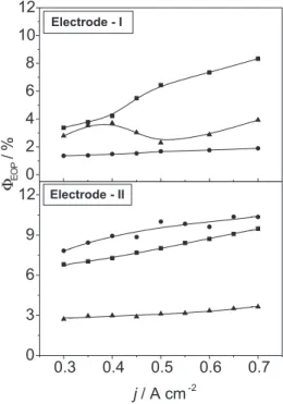
CI, CE, and CT are the internal, external and total differential capacities, respectively. CI and CE respectively represent the contribution to the total film surface of the more internal (more difficult-to-access) and the more external (easy accessible) surfaces. ϕ is an intensive parameter defined as CI/CT, called the morphology factor91. Figure 3 exemplifies the influence of current density and
electrode morphology on ΦEOP, for different electrolytes, at 0 oC.
As shown by Figure 3, with the exception of the BSE (both electrodes) and BSE + 0.03 mol dm-3 F- (at Electrode-I), significant
improvements in current efficiency are observed in the presence of
fluoro-anions. Once a minimum ΦEOP value is reached, gain in O3 -production by further increasing the current density is only of minor importance. According to eq.15 such behaviour indicates a constant coverage by intermediates leading to EOP.
For the same electrolyte comparing the ΦEOP -values at the two electrodes (see Fig.3), with the exception of BSE where approximately the same ΦEOP-values are obtained, significant differences are observed in the presence of 0.03 mol dm-3 F- and 0.10 mol dm-3 BF
4
-. Since for
the BSE ΦEOP -values are not significantly affected by the electrode morphology, the effect observed in the presence of fluoro-anions cannot be explained by the change in surface area of the two electrode (see Table 1). An even more intriguing result is the effect of BF4
-which, using the BSE as a reference, can act depending on electrode morphology as a promoter (Electrode-II) or inhibitor (Electrode-I) of the EOP process.
Influence of current density and temperature on ΦEOP
The influence of the temperature on ΦEOP depends on electrode material and nature of the electrolyte. Representative j vs. ΦEOP cur-ves for temperatures between 0 and 40 oC are shown in Figure 4 for
BSE containing 0.10 mol dm-3 HBF
4 at electrode-II. One can
obser-ve that ΦEOP-valuesdecrease with increasing temperature. This behaviour is normally found in investigations using temperature values ≥ 0 oC and can be understood considering the increase in the
anodic potential with decreasing temperature combined with a lower O3 decomposition rate when the temperature is decreased4,34.
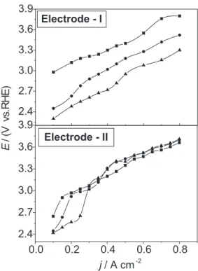
Influence of electrode morphology and electrolyte on the polarisation curves obtained point-by-point
Figure 5 shows representative polarisation curves, at 0 oC, for
the different electrolytes investigated. All potentials were corrected for ohmic drop.
As shown in Figure 5 the influence of the fluoro-anions on the E vs. j profiles reveals to be dependent on electrode morphology. While in the case of the more compact coating (Electrode-I) the fluoro-anions cause an expressive effect on η over the complete current interval investigated, for the less compact coating (Electrode-II) the influence of the fluoro-anions is mainly verified at j ≤ 0.3 A cm-2.
The above results clearly establish a dependency between electrode morphology and ΦEOP emphasising the need for a detailed investigation of the electrode preparation parameters in order to optimise ΦEOP and reach a better understanding of the fundamental aspects involved.
Table 1. Surface parameters as function of electrode preparation
β-PbO2 CT CE CI
Electrode* mF cm-2 mF cm-2 mF cm-2 ϕ
I 58 15 43 0.74
II 100 22 78 0.78
*β-PbO2 depositionwas done at constant anodic current: j = 5 mA cm-2 (Electrode-I) or 20 mA cm-2 (Electrode-II) using a 40 min
depo-sition time.
Figure 3. Influence of current density, j, on ozone efficiency, ΦEOP, for different electrolytes and electrode morphology (Electrodes I and II). () BSE, 3.0 mol dm -3 H
2SO4; () BSE + 0.10 mol dm -3 HBF
4; () BSE + 0.03 mol dm -3
NaF. T = 0 °C
Figure 4. Influence of temperature on the ΦEOP vs. j behaviour. Electrode-II. Electrolyte: 3.0 mol dm-3 H
2SO4 containing 0.10 mol dm -3 HBF
Status of the ozonation systems development
Among the various electrochemical EOP technologies, the solid polymer electrolyte, SPE, technology is particularly interesting16,22,26,
since it can operate in electrolyte-free water and hence allows in situ ozonation in water/effluent streams. This system, also called Membrel process, is an example of the way EOP can be commercially relevant, with Japanese, French and Swiss companies offering products based on this approach40.
In the SPE technology, porous electrodes are pressed onto a proton-exchange membrane (PEM) and pure water is electrolysed to produce a mixture of O2 and O3 on the backside of the anode and H216,34,92 or H
2O2
93 on the cathode. Lead dioxide, PbO
2, has been used
as anode and the most widely employed PEM is Nafion 16,22,26,34.
Other membranes such as BAM and DAIS 94-96 have been studied
because of high Nafion price. These membranes are perfluorinated sulphonic acid polymers, which perform as a separator and a solid electrolyte due to the highly acidic environment produced by the sulphonic acid groups. Thus, PEM exhibits excellent electrochemical and mechanical stability, high protonic conductivity, an appropriate electric conductivity and low gas permeability97.
The SPE technology has the advantage of directly dissolving a high concentration of O3 into water, and thus, to some extent, eliminates problems of contacting gas-phase ozone into wastewater (a usual problem for corona ozonizers)40. A further advantage is that
SPE cells can operate at several amps per square centimetre with typical thickness of a few millimetres. Thus a low ohmic drop is observed across the membrane resulting in lower electrical energy consumption97. An especially attractive feature and a major advantage
of the SPE technology is the possibility to operate at room temperature with high current efficiency for EOP. In fact, Stucki et al.16,34 observed
ΦEOP-values of about 18% at 30 ºC. Similar results were obtained by
Zhou et al.26. In another investigation, Beaufils et al.92 reported Φ
EOP of 7% at 30 ºC. According to the authors, for similar experimental conditions (anolyte temperature, anode composition and current density), the cell configuration strongly influences EOP. This is certainly due to the rate of heat removal by different SPE cell designs, which affects the local anode temperature and consequently the rate of thermal O3 decomposition.
With respect to corrosion stability of PbO2, two properties of the membrane cell design seem to be decisive. The electrolyte is convection-free thus preventing mechanical wear of the anode coating. Foller and Tobias17 proposed a chemical dissolution mechanism of
PbO2 when an interlayer having a very high proton activity builds up near the anode surface. In the case of the SPE cell, the absence of concentration gradients at the anode surface reduces drastically this dissolution. The small amount of PbO2 that does dissolve is re-deposited immediately onto the surface because of unfavourable transport conditions for its removal from the electrode (absence of convection)17. Therefore, it was possible to operate SPE cells
continually at 1 A cm-2 for more than 3 years34.
Ozone reactors based on the SPE technology permit a wide variety of cell design configuration (water flux, current density, temperature) capable to promote high ΦEOPand low electrical consumption compared to other electrochemical processes. Based on the significant advantages of the SPE technology, our laboratory initiated an investigation of these parameters in an ozone reactor.
Applications of Ozone in Green Chemical Processes
The removal of organics from wastewaters and effluents has become an increasingly important issue because of steadily increasing industrial activities. Important sources of contamination are the pulp and paper mill industry, the petrochemical industry, the food-processing industry, and runoff from urban areas.
The first studies involving reactions between organics and ozone were conducted by Schönbein46, Baumer98 and von Gorup-Besanez99.
Wood, straw, corks, starch, humus, natural rubber, fats, alcohol, albumin, all are acted on by ozone. The bleaching effect produced by ozone on indigo was used by Schönbein46 as a base of a method
to quantitatively determine ozone concentrations. Ozone also has been applied as a selective disinfectant in brewing and cider manufacturing and additional uses include the production of oils, greases, dyes and soap100. Details on the treatment of
municipal/in-dustrial effluents are also available100.
Traditionally, chlorine dioxide, ClO2, has been a widely used and efficient bleaching agent of the wood pulp industry, causing, however, severe aggression to the environment14,16. Since the 80’s, in
Norway100, paper bleaching technology based on ozone has been
developed to the commercial demonstration stage.
During degradation of organics only extended ozonation would lead to “full mineralization”, i.e., to CO2, H2O, NO3-, etc. For physical,
technical or economical reasons, in practice, ozonation processes are stopped long before total mineralization. The rate expression for the removal of any organic pollutant is given by61,101:
–d[X]/dt = kobs . [O3(aq)] . [X] (17) where X is the organic pollutant, kobs (= nk) is the product of the actual rate constant and the stoichiometric factor, n, reflecting oxidation of daughter products (see scheme below).
Figure 5. Dependence of the E vs. j profiles on electrolyte composition and electrode morphology (Electrodes I and II). E-values corrected for ohmic drop. Data points were taken point-by-point under galvanostatic polarisation. () BSE, 3.0 mol dm -3 H
2SO4; () BSE + 0.10 mol dm -3
HBF4; () BSE + 0.03 mol dm
Slow ozone reactions (kobs < 100 mol-1 s-1) are generally related
to direct O3-reaction and depend on dissolved ozone concentration. These ozonations are usually not carried out with air-fed corona sources. When reaction rates are the rate limiting process, high available ozone concentration from EOP can be especially beneficial. Nevertheless, oxidations with ozone are often rapid and do not impose limitations on current commercial processes40. The ozonation of
phenol, chlorophenols, cresols, cyanide ion, sulphide ion, mercaptans and many amines present kobs≥ 104 mol-1 s-1. High electrochemical
ozone concentration can also be of benefit in these cases, due to the possibility of using improved mass transfer rates, which means decrease capital costs.
In water, the direct reaction of dissolved ozone can hardly be separated from other reactions that arise from decomposition of aqueous ozone to secondary oxidants that are much more reactive than ozone itself101. Of all the secondary oxidants, the hydroxyl
radi-cal (OH•) plays a key role. These radicals can easily oxidise all types
of organic contaminants and many inorganic solutes by a radical-type reaction. These radicals are immediately consumed on their formation and exhibit little substrate selectivity61,102. Even organic
substances that are known to be non-reactive with ozone or other oxidants, can be attacked by OH•.
In order to enhance the ozonation efficiency, efforts have been undertaken to increase the rate of its dissociation in aqueous solutions61. Advanced oxidation processes (AOP’s) have been
developed using UV-light or H2O2, in addition to ozone, in order to accelerate its decomposition rate in water thus increasing the production of hydroxyl radicals (once ozone enters water, it becomes highly unstable and rapidly decomposes through a complex series of reactions initiated by OH--anions59).
CONCLUSIONS
This article shows EOP is a environmental friendly technology with potential application in several Green Chemical Processes. Fun-damental investigations of new electrode materials, having a higher overpotential for the OER, are highly desirable for the further advances in the EOP technology. Also, supporting electrolytes containing fluoro-anions surely improve the efficiency of the electrode process for O3-production including reducing energy consumption. Papers dealing with cell technology has appeared in the literature and show good performance for EOP. As seen here, there is no doubt that advances in electrochemical ozone generation technology allied with its favourable oxidant properties, certainly will stimulate even more its use in many different processes. Contrary to the corona technology, the electrochemical technology can generate higher O3 concentrations, which are essential in “slow” oxidative reactions. Although operational costs of the corona technology is still lower than EOP, new technologies based on SPE cells are promising as an ozone source for many applications. As mentioned to reach a better understanding of EOP more detailed investigations are still necessary of such issues as electrode preparation parameters and anion adsorption phenomenon at the anode surface.
ACKNOWLEDGEMENTS
L. M. Da Silva and M. H. P. Santana wish to thank the Ph.D. fellowships received from the FAPESP Foundation. J. F. C. Boodts wishes to thanks a Visiting Researcher Fellowship granted by the CNPq.
REFERENCES
1. Walsh, F. C.; Pure Appl. Chem.2001, 73, 1819.
2. Armor, J. N.; Appl. Catal., A1999, 189, 153.
3. Vastag, G.; Szöcs, E.; Shaban, A.; Kálman, E.; Pure Appl. Chem.2001, 73, 1861.
4. Da Silva, L. M.; De Faria, L. A.; Boodts, J. F. C.; Pure Appl. Chem.2001, 73, 1871.
5. Mackenzie, K. J.; Marken, F.; Pure Appl. Chem.2001, 73, 1885. 6. Rusling, J. F.; Pure Appl. Chem.2001, 73, 1895.
7. Sánchez-Sánchez, C. M.; Montiel, V.; Tryk, D. A.; Aldaz, A.; Fujishima, A.; Pure Appl. Chem.2001, 73, 1917.
8. Lorimer, J. P.; Mason, T. J.; Plates, M.; Phull, S. S.; Walton, D. J.; Pure Appl. Chem.2001, 73, 1957.
9. Brett, C. M. A.; Pure Appl. Chem.2001, 73, 1969. 10. Trasatti, S.; Int. Hydrogen Energy 1995, 20, 835.
11. Tatapudi, P.; Fenton, J. M. In Environmental Oriented Electrochemistry; Sequeira, C. A. C., ed.; Elsevier: Amsterdam, 1994, p. 103.
12. Hileman, B.; C and EN1992, 13, 7.
13. Lipsztajn, M. In Electrochemical Engineering in the Chor-Alkali and Chlorate Industries; Hine, F.; Darlington, W. B.; White, R. E., eds.; The Electrochemical Society: Pennington, 1998, vol. 88, p. 177.
14. Meng, M. X; Hsieh, J. S.; Tappi J. 2000, 83, 67.
15. Hill, A. G.; Rice, R. G. In Handbook of Ozone Technology and Applications; Rice, R. G.; Netzer, A., eds.; Ann Arbor Science: Michigan, 1982, vol. 1, p. 15.
16. Stucki, S.; Theis, G.; Kötz, R.; Devantay, H.; Christen, H.; J. Electrochem. Soc.1985, 132, 367.
17. Foller, P. C.; Tobias, W.; J. Electrochem. Soc. 1982, 129, 506. 18. Foller, P. C.; Goodwin, M. L.; Ozone: Sci. Eng. 1984, 6, 29.
19. Ota, K.; Kaida, H.; Kamiya, N.; Denki Kagaku Oyobi Kogyo Butsuri Kagaku1987, 55, 465.
20. Shepelin, V. A.; Babak, A. A.; Potatova, G. F.; Kasatkin, E. V.; Roginskaya, Y. E.; Elektrokhimiya1990, 26, 1142.
21. Wen, T. C.; Chang, C. C.; J. Chin. Inst. Chem. Eng. 1992, 23, 397. 22. Tatapudi, P.; Pallav, J. M.; J. Electrochem. Soc. 1993, 140, 3527. 23. Wen, T. C.; Chang, C. C.; J. Electrochem. Soc. 1993, 140, 2764. 24. Feng, J.; Johnson, D. C.; Lowery, S. N.; Carey, J. J.; J. Electrochem. Soc.
1994, 141, 2708.
25. Potapova, G. F.; Kasatkin, E. V.; Nikitin, V. P.; Shestakova, O. V.; Blinov, A. V.; Mazanko, A. F.; Sorokin, A. I.; Asaturov, S. A.; Bashk. Khim. Zh. 1995, 2, 65.
26. Zhou, Y.; Wu, B.; Gao, R.; Zhang, H.; Jiang, W.; Yingyong Huaxue1996, 13, 95.
27. Perret, A.; Haenni, W.; Niedermann, P.; Skinner, N.; Comminellis, C.; Gandi, D.; Proc. - Electrochem. Soc. 1997, 97.
28. Kim, J. K.; Choi, B. S.; Hwahak Konghak1997, 35, 218.
29. Chernik, A. A.; Drozdovich, V. B.; Zharskii, I. M.; Russ. J. Electrochem. 1997, 33, 259.
30. Chernik, A. A.; Drozdovich, V. B.; Zharskii, I. M.; Russ. J. Electrochem. 1997, 33, 264.
31. Fateev, V. N.; Akel’kina, S. V.; Velichenko, A. B.; Girenko, D. V.; Russ. J. Electrochem. 1998, 34, 815.
32. Babak, A. A.; Amadelli, R.; Fateev, V. N.; Russ. J. Electrochem. 1998, 34, 149.
33. Katsuki, N.; Takahashi, E.; Toyoda, M.; Kurosu, T.; Lida, M.; Wakita, S.; Nishiki, Y.; Shimamune, T.; J. Electrochem. Soc. 1998, 145, 2358. 34. Stucki, S.; Baumann, H.; Christen, H. J.; Kötz, R.; J. Appl. Electrochem.
1987, 17, 773.
35. Kötz, R.; Stucki, S.; J. Electroanal. Chem. 1987, 228, 407.
36. Babak, A. A.; Amadelli, R.; De Battisti, A.; Fateev, V. N.; Electrochim. Acta 1994, 39, 1597.
37. Velichenko, A. B.; Girenko, D. V.; Kovalyov, S. V.; Gnatenko, A. N.; Amadelli, R.; Danilov, F. I.; J. Electroanal. Chem. 1998, 454, 203. 38. Amadelli, R.; Armelao, L.; Velichenko, A. B.; Nikolenko, N. V.; Girenko,
D. V.; Kovalyov, S. V.; Danilov, F. I.; Electrochim. Acta1999, 45, 713. 39. Foller, P. C.; Tobias, W.; J. Phys. Chem. 1981, 85, 3238.
40. Foller, P. C.; Kelsall, G. H.; J. Appl. Electrochem. 1993, 23, 996. 41. Beaufils, Y.; Bowen, P.; Wenzed, C.; Comninellis, C.; Proc. - Electrochem.
Soc. 1998, 97.
42. Amadelli, R.; De Battisti, A.; Girenko, D. V.; Kovalyov, S. V.; Velichenko, A. B.; Electrochim. Acta2000, 46, 341.
43. Da Silva, L. M.; De Faria, L. A.; Boodts, J. F. C.; Electrochim. Acta2003, 48, 699.
44. Graves, J. E.; Pletcher, D.; Clarke, R. L.; Walsh, F. C.; J. Appl. Electrochem. 1992, 22, 200.
45. Rideal, E. K.; Ozone, Constable and Co: London, 1920.
46. Schönbein, C. F.; Comptes Rendus Hebd. Seances Acad. Sci.1840, 10, 706. 47. de la Rive; Marignac, P.; Comptes Rendus Hebd. Seances Acad. Sci.1845,
48. Hunt, T. J.; J. Am. Sci. 1848, 6, 171
49. Bailey, P. S.; Ozonation in Organic Chemistry, Academic Press: New York, 1978, vol. 1, p. 8.
50. Kirk, R. E.; Othmer, D. F.; Encyclopaedia of Chemical Technology, John Wiley and Sons: New York, 1981, vol. 16, p. 683.
51. Hill, A. G.; Rice, R. G. In ref. 15, p. 1.
52. Glaze, W. H.; Kang, J.; Chapin, D. H.; Ozone: Sci. Eng.1987, 9, 335. 53. von Siemens, W.; Poggendorff’s Ann. 1857, 102, 120.
54. Carlins, J. J.; Clark, R. G. Inref. 15, p. 41.
55. Bensen, S. W. In Ozone Chemistry and Technology; Advances in Chemistry Series No.21, American Chemical Society: Washington, 1959, p. 405. 56. Popovich, M. P.; Zhitnev, Y. N.; Filippov, Y. V.; Russ. J. Phys. Chem. 1971,
45, 2.
57. Cromwell, W. E.; Manley, T. C. In ref. 15, p. 304.
58. Rosen, H. M.; Ozone in Water and Wastewater Treatment, Ann Arbor Science: Michigan, 1972, p. 101.
59. Pontius, F. W.; Water Quality and Treatment, 4th ed., McGraw-Hill: New York, 1993.
60. Suarasan, I.; Ghizdavu, L.; Budu, S.; Dascalescu, L.; J. Electrostat.2002, 54, 207.
61. Shin, W. T.; Mirmiran, A.; Yiacoumi, S.; Tsouris, C.; Sep. Purif. Technol. 1999, 15, 271.
62. Sun, B.; Sato, M.; Harano, A.; Clements, J. S.; J. Electrostat.1998, 43, 115.
63. Lubucki, P.; Jayaram, S.; Cross, J. D.; Conference Record of ICDL, Rome, Italy, 1996, p. 427.
64. Goheen, S. C.; Mong, G. M.; Pillay, G.; Camaioni, D. M.; First International Conference on Advanced Oxidation Technology for Water and Remediation, London, Ont, 1994, p. 83.
65. Masten, S. J.; Davies, S. H. R.; Environ. Sci. Technol.1994, 28, 180. 66. Groth, W.; Z. Phys. Chem1937, 37, 307.
67. Wulf, O. R.; Melvin, E. H.; Phys. Rev.1931, 38, 330.
68. Volman, D. H.; Advances in Photochemistry, Interscience Publishers: New York, 1963, vol. 1, p. 43.
69. DuRon, B. Inref. 15, p. 77.
70. Prengle, H. W. In Proc. International Ozone Association, Cincinnati, 1977. 71. Foller, P. C. Inref. 15, p. 85.
72. Foller, P. C.; Goodwin, M. L.; Chem. Eng. Prog.1985, 81, 49. 73. Wabner, D.W.; Grambow, C.; J. Electroanal. Chem. 1985, 195, 95. 74. Da Silva, L. M.; Franco, D. V.; Boodts, J. F. C.; Electrochim. Acta,
submitted.
75. Santana, M. H. P.; Boodts, J. F. C.; unpublished work.
76. Da Silva, L. M.; Boodts, J. F. C.; unpublished work. 77. McLeod, J. R.; J. Chem. Soc. 1886, 49, 591.
78. Fischer, F.; Massennez, K.; Z. Anorg. Chem. 1907, 52, 202. 79. Briner, E.; Haefeli, R.; Paillard, H.; Helv. Chim. Acta1937, 20, 1510. 80. Seader, J. D.; Tobias, C. W.; Ind. Eng. Chem. 1952, 44, 2207.
81. Putnam, G. L.; Moulton, R. W.; Fillmore, W. W.; Clark, L.; J. Electrochem. Soc. 1948, 93, 211.
82. Lash, E. I.; Hornbeck, R. D.; Putnam, G. L.; Boelter, E. D.; J. Electrochem. Soc. 1951, 98, 134.
83. Semchenko, D. P.; Lyubushkina, E. T.; Lyubushkin, V.; Élektrokhimiya 1973, 9, 1744.
84. Semchenko, D. P.; Lyubushkina, E. T.; Lyubushkin; V.; Tovarnye Znaki 1974, 51, 225.
85. Semchenko, D. P.; Lyubushkina, E. T.; Lyubushkin, V.; Tekn. Nauk1975, 3, 98.
86. Fritz, H. P.; Thanos, J.; Wabner, D. W.; Z. Naturforsch1979, 34, 1617. 87. Pleskov, Y. V.; Russ. Chem. Rev.1999, 68, 381.
88. Leitzke, O. In Internationales Symposium Ozon und Wasser; Berlin, 1977, p. 164.
89. Trasatti, S. In Electrodes of Conductive Metallic Oxides; Trasatti, S., ed., Elsevier: Amsterdam, 1981, Parts A and B.
90. Da Silva, L. M.; De Faria, L. A.; Boodts, J. F. C.; J. Electroanal. Chem. 2002, 532, 141.
91. Da Silva, L. M.; De Faria, L. A.; Boodts, J. F. C.; Electrochim. Acta. 2001, 47, 395.
92. Beaufils, Y.; Comninellis, C.; Bowen, P. In Proc. ICHEME Symposium Series, 1999, p. 191.
93. Tatapudi, P.; Fenton, J. M.; J. Electrochem. Soc. 1994, 141, 1174. 94. Beattie, P. D.; Francesco, P. O.; Basura, V. I.; Zychowska, K.; Ding, J.;
Chuy, C.; Schmeisser, J.; Holdcroft, S.; J. Electroanal. Chem. 2001, 503, 45.
95. Beattie, P. D.; Basura, V. I.; Holdcroft, S.; J. Electroanal. Chem. 1999, 468, 180.
96. Basura, V. I.; Chuy, C.; Beattie, P. D.; Holdcroft, S.; J. Electroanal. Chem. 2001, 501, 77.
97. Michas, A.; Millet, P.; J. Membr. Sci. 1991, 61, 157.
98. Wetherill, C. M. In Ozone and Antozone, Annual Report of the Board of Regents of the Smithsonian Institution; U.S. Government Printing Office, Washington, 1865, p. 167.
99. von Gorup-Besanez, E.; Justus Liebig’s Ann. Chem. 1859, 110, 86. 100. Hill, A. G.; Rice, R. G. In ref. 15, p. 9.