Abstract
A combined plate element is presented for the analysis of transverse and longitudinal vibrations of a thin plate which carries a load moving along an arbitrary trajectory with variable velocity. Depending on the acceleration of the point load on its trajectory on the plate surface, the combined element, which is a combination of the 24 DOF plate element and an equivalent mass element, represents transverse (z) inertia, Coriolis and centripetal and longitudinal (x, y) inertia effects of the moving load. In order to obtain the combined element, mass, damping and stiffness matrices of the equivalent mass element repre-senting the mass are first derived by using the relations between nodal forces, nodal deflections and deflection-shape functions of the plate element and the inertia and other forces of the moving mass according to the global coordinates on the plate and local coordinates on the plate element. Then, the obtained property matrices of the equivalent
mass element and property matrices of the plate element were added
together in order to obtain the combined plate element. For verifica-tion, the suggested technique was applied on a simply supported beam-plate under a moving load, and agreements were obtained with existing literature. In addition, intensive analysis and simulations were conducted at different dimensionless mass rates (mass of the load/mass of the plate) and angular velocities for a circular motion on a CCCC plate, and the results are provided. Furthermore, analysis results are provided for moving force condition which neglects the inertia, Coriolis and centripetal effects of the load, and it was shown that the moving mass assumption generated very different results with moving load assumption especially at high mass ratio and velocity values. Analysis results made it clear that the dynamic behaviour of the plate was differently affected by an orbiting mass depending on its mass ratio, orbiting radius and angular velocity
Keywords
Orbiting mass; combined plate element; plate vibrations; moving load.
A new FEM procedure for transverse and longitudinal vibration
analysis of thin rectangular plates subjected to a variable velocity
moving load along an arbitrary trajectory
İsmail Esen
Karabük University, Balıklar Kayası Mevkii, 78050, Karabük, Turkey
Corresponding author: [email protected]
http://dx.doi.org/10.1590/1679-78251525
Latin A m erican Journal of Solids and Structures 12 (2015) 808-830 1 INTRODUCTION
Vibration of solids and structures under moving loads is a significant problem for civil and machine constructions and has been studied by several researchers. One of the important studies in this area, Nikkhoo et al. (2012), examined the dynamic behavior of a thin plate excited by a moving mass using the Eigen function expansion method, whereas some researchers investigated the dynamic behavior of a Mindlin plate (Gbadeyan and Oni, 1995; Faria and Oguamanam, 2004; Gbadeyan and Dada, 2006; Amiri et al., 2013). Among the important FEM studies, Wu (2007) presented a moving load element taking into consideration the effects of the load for the dynamic analysis of inclined plates under moving loads. In another study, Wu (2005) used scale beams and scaling laws for the analyses of a rectangular plate under the effect of a line load. Some researchers (Eftekhari and Jafari, 2012) presented a method which is the combination of differential Quadrature (DQ) method and integral Quadrature (IQ) method of the Ritz method for a vibration problem of the plates sub-jected to masses that travel with acceleration. Representing the moving mass with all effects in a new finite element formulation, Esen (2013) presented a method that can be used in the analysis of transverse vibrations of thin rectangular plates under the effect of constant-velocity-moving loads. In a similar fashion, the same topic was studied semi-analytically by Sharbati and Szyszkowski (2011), using a composite beam element. Similar to the mesh refinement method provided in Faria and Oguamanam (2004), dynamic behaviors of angled stratified composite plates were examined with FEM in Ghafoori and Asghari (2010). Nowadays the importance of dynamic behavior of struc-tures subjected to accelerated loads is increasing, and some researchers (Lee, 1996; Wang, 2009; Mamandi et al., 2010; Esen, 2011) studied the dynamic behavior of composite and uniform beams under accelerated loads. Using the FEM, some researchers (Wu et al., 2001; Gerdemeli et al., 2011) have modelled the moving mass problem for beams. The separation phenomenon which can occur at some values of travelling velocities and system parameters during their travel can cause fundamen-tal change in the dynamic behavior of structures (Lee, 1998). As for different engineering applica-tions of moving mass structure problems, (Meirovitch, 1967; Yoshida and Weaver, 1971; Bathe, 1982; Reddy, 1984; Yang, 1986; Taheri, 1987; Bachmann, 1995; Kadivar and Mohebpour, 1998; Fryba, 1999; Wilson, 2002; Clough and Penzien, 2003; Szilard, 2004; Mohebpour et al., 2011; Oni and Awodola, 2011; Awodola, 2014) can be considered important and valuable references for analyt-ical and FEM solutions and analysis of dynamic systems.
over-Latin A m erican Journal of Solids and Structures 12 (2015) 808-830
come, which sometimes urges researchers to neglect the inertia effects of the mass and the damping in the system, and in some cases, moreover, it causes simplification of the geometry and prevents the acquisition of the real behavior of the designed system. Further studies are necessary to analyze the dynamic behavior of structural systems without neglecting all inertia effects and damping in the system in moving mass-structure systems and taking into consideration variable-velocity accelerat-ing and decelerataccelerat-ing situations of the mass as well as its motion on different trajectories on struc-tural systems. The new method suggested by this study which does not require the limitations men-tioned above has the advantage of being used by adapting to the classical finite elements method; in addition, it meets an important need by modelling the transverse and longitudinal dynamic behav-ior of thin plates subjected to moving loads and under variable geometry and boundary conditions, along with the damping effects of the system and convective acceleration components of the varia-ble velocity mass as well as variavaria-ble mass travel orbits.
In this paper, the discreet governing equation of motion of a thin rectangular plate on which a mass travels with variable velocity in arbitrary orbit was obtained by combining the mass, stiffness and damping matrices of the mass with the property matrices of the plate. Property matrices of the accelerated mass were calculated through the time-dependent second-order total differential of the deflection function at variable mass contact point and the nodal forces and deflections of the plate element which the moving mass applies. Inertia effects were taken into consideration in the evalua-tion of in-plane and out of plane dynamic responses of the plate. Using the method recommended in this study, the dynamic response of the systems under moving loads with mass motions on orbiting path which can be found in rotating machines and similar systems as well as on rectilinear path which can be found in slab type bridges and similar structural systems can be analyzed.
2 PROBLEM DEFINITION
In the formulation the following assumptions will be adopted (Fig. 1)
The mass inertia is considered.
The mass is always in contact with the plate.
The plate is thin and small displacements in the plate occurred according to Kirchhoff theory.
The plate is of constant thickness and constant mass of unit area.
The trajectory of the mass is defined by time-dependent xp t and yp t coordinates.
Under the above assumptions and neglecting damping, the equation of motion for constant mass velocity can be written as follows:
2 2
4
2 2
d ( , , )
( ( )) ( ( ))
d
p p
p p p
w x y t w
D w m g x x t y y t
t t (1)
In Eq. (1), D is the bending rigidity, D Eh3 12 1 v2 , where E, υ, and h represent Young's modulus ”f elasticity, P”iss”“’s ratio and thickness respectively and μ is the mass of unit area of the plate. And w w x y t, , is the vertical deflecti”“ ”f the plate’s mid-surface at point with
co-ordinates x and y at time t, while x xp t and y yp t represent the Dirac-delta
func-( ) ( )
( ) ( )
( )
Latin A m erican Journal of Solids and Structures 12 (2015) 808-830
tions in x and y directions, respectively. The symbols mp and g are the moving mass and gravita-tional acceleration, respectively.
Assuming that xp and yp coordinates, which define the mass motion on the plate, are function
of time and the acceleration (d2 , , d2
p p
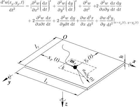
w x y t t ) on the right side of Eq. (1) is calculated from the second-order total differential of plate deflection function (Fryba, 1999):
2 2
2 2 2 2 2
2 2 2 2
2 2 2 2
( ), ( )
2 2
d ( , , ) d d d d
[ +2
d d d d
d
d d d d
2 2 + ]
d d d d p p
p p
x x t y y t
w x y t w x w y w w x y
t t x y t t
t x y t
w x w y w x w y
x t t y t t x t y t
(2)
y
x
z
l
p
(t)
x
l
O
h
y
p(t)
m
pk
v (t )
m, m
a
x y
Figure 1:A moving mass travelling along an arbitrary trajectory on the surface of a rectangular plate and the kth plate element on which the moving mass applies.
The solution of the motion equation given in Eq. (1) can be obtained for any prescribed initial and boundary conditions by using analytical methods given in the literature, i.e. in Bachmann (1995); Nikkhoo and Fayaz (2012). In this study, including damping, the more accurate dynamic behaviour of the mass-plate system can be determined with the method which will be explained below. The finite element formulation of the system is obtained, evaluating the contact forces be-tween the mass and the plate on the right hand side of the Eq. (1)
2.1 Finite element formulation of a mass that moves along an arbitrary path on a plate with variable velocity
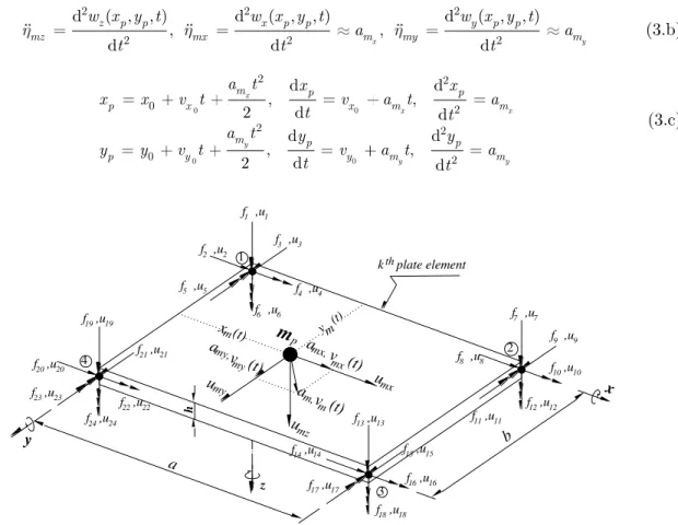
According to the local x, y, z coordinates of the plate element seen in Figure 2 and the positions
m
x t and ym t of the mass on the plate element, the in-plane forces (Fx and Fy) and
out-of-plane force (Fz) on p, which is the contact point induced by mp due to the vibration and curvature
of the plate element are as given in Gbadeyan and Oni (1995), respectively:
( ( ))
( ( ))
( ( )) ( ( ))
x p mx p
y p my p
z p p mz p p
F m x x t
F m y y t
F m g m x x t y y t
(3.a)
( )
Latin A m erican Journal of Solids and Structures 12 (2015) 808-830
with,
2 2 2
2 2 2
d ( , , ) d ( , , ) d ( , , )
, ,
d d x d y
z p p x p p y p p
mz mx m my m
w x y t w x y t w x y t
a a
t t t (3.b)
0 0 0 0 2 2 0 2 2 2 0 2 d d , ,
2 d d
d d
, ,
2 d d
x
x x
y
y y
m p p
p x x m m
m p p
p y y m m
a t x x
x x v t v a t a
t t
a t y y
y y v t v a t a
t t
(3.c)
v (t)
m
x y z 1 2 3 4 a b m x (t) hf ,u1 1
y m (t)
amx,
f ,u3 3
f ,u4 4 f ,u5 5
f ,u2 2
f ,u7 7
f ,u8 8
f ,u9 9
f ,u10 10
f ,u13 13
f ,u14 14
f ,u16 16 f ,u17 17
f ,u18 18 f ,u19 19
f ,u22 22 f ,u20 20
f ,u23 23
f ,u24 24
f ,u6 6
f ,u11 11
f ,u12 12
f ,u15 15
f ,u21 21 p
mx v (t)
amy, my
v (t) am,
m
umx umy
umz
k plate elementth
Figure 2: The rectangular plate element on which the moving mass mp applies at time t , with dimensions a and b and equivalent nodal deflections and forces.
where wx x y tp, p, , wy x y tp, p, , wz x y tp, p, are deflections in x, y and z directions respectively at contact point. While x0, y0 and vx0, vy0 are respectively initial positions and velocities of the mass whe“ time is zer” ; amx and amy are components of acceleration vector of the mass in x and y
di-rections. For vibrations of the plate in longitudinal x and y directions, the derivation procedure of
accelerations x m u and y m
u , in Eq. (3.b), are provided in Appendix A. For the uniformly-accelerated
motion according to (3.b) and (3.c), the vertical acceleration in Eq. (2) is in the following form: (3)
0 0 0 0
0
2 2
0
( ) ( ) 2( )( ) 2( )
2( )
x y x y x x
y x y
mz x x m y y m x m y m xy m x
y m y m x m y
w v a t w v a t w v a t v a t w v a t w
v a t w a w a w (4)
Eq. (4) was substituted into the last equation of (3.a). It becomes:
0 0 0 0
0 0
2 2
{ ( ) ( ) 2 ( )( )
2 ( ) 2 ( ) } ( ) ( )
[
]
x y x y x y
x y
z p x x m y y m xy x m y m m x m y
x x m y y m p p
F m g w v a t w v a t w v a t v a t a w a w
w w v a t w v a t x x y y
(5.a)
Latin A m erican Journal of Solids and Structures 12 (2015) 808-830
where “ ′ ”, “∙ ” are, respectively, spatial and time derivatives of deflections; and, since the mass moves along the deflected shape of the plate, one can divide the vertical force Fz into three
compo-nents that are
2 2
0 0 0 0
[ ( ) ( ) 2 ( )( ) ]
p x x mx y y my xy x mx y my mx x my y
m w v a t w v a t w v a t v a t a w a w (5.b)
p
m w (5.c)
0 0
2m w vp[ x( x amxt) w vy( y amyt)] (5.d)
Eqs. (5.b), (5.c) and (5.d) are, respectively, the centripetal force, the inertia force and the Coriolis force components. The subscripts “ x” and “y” show that the function of deflection is derived by x and y, respectively.
The rectangular plate element in Figure 2 is a 24- DOF conforming plate element with C(1) con-tinuity conditions at element boundaries. It includes constant twist ( 2w x y) at corner nodes. Therefore, each corner nodal deflection is (Szilard, 2004): (5)
1 2 3 4 5 6
( =1,2, 3, 4 : nodes of the plate element)
T T
i i i i i i i z x y x y xy i
u u u u u u u w w w
i
(6)
where wz, wx and wy are, respectively, the vertical deflection, the longitudinal x and y deflections
of ith nodal point, and i
x and yi , xyiare, respectively, rotation about x and y-axis and twist of
nodal point i.
For simplification let us use three types of indexes: i =2, 8, 14, 20 for longitudinal x, i =3, 9, 15,
21 for longitudinal y, i =1, 4, 5, 6, 7, 10, 11, 12, 13,17, 18, 19, 22, 23, 24 for transverse z and i =1,
2, ..., 24 for everything together. The following indexes can be defined as:
2, 8,14,20
x
I (7.a)
3, 9,15,21
y
I (7.b)
1, 4, 5, 6, 7,10,11,12,13,16,17,18,19,22,23, 24
z
I (7.c)
1,2,...,24
x y z
I I I I (7.d)
The equivalent nodal forces of the kth plate element are obtained using all forces in Eqs. (3) and
(5) and the shape functions of the 24 DOF plate element given in Figure 2 (Clough and Penzien, 2003; Wu, 2007):
, ( )
i
k i p mx x x
f m i I (8.a)
, ( )
i
k i p mx y y
f m i I (8.b)
0 0 0 0
0
2 2
0
{ ( ) ( ) 2 ( )( )
2 ( ) 2 ( ) }, ( )
[
]
i x y x y x
y x y
k i p x x m y y m xy x m y m m x
m y x x m y y m z
f m g w v a t w v a t w v a t v a t a w
a w w w v a t w v a t i I (8.c)
{ } { }
{ }
Latin A m erican Journal of Solids and Structures 12 (2015) 808-830
where i (i I) are shape functions of the plate element given by Szilard (2004), see Appendix. B. The relations between shape functions and deflections (in- plane x and y deflections and out of
plane z deflection) of the plate element at position x and y, and time t, are (Szilard, 2004):
( , )
x i i
i Ix
w x y u (9.a)
( , )
y
y i i
i I
w x y u (9.b)
( , )
z
z i i
i I
w x y u (9.c)
The deflections of the contact point of the mass on the plate element in terms of the nodal de-flections of the plate element can also be obtained as follows:
x
mx j j
j I
u (10.a)
y
my j j
j I
u (10.b)
z
mz j j
j I
u (10.c)
where ui (i I) are the deflections of the nodes of the plate element at which the moving mass
p
m locates. Substituting Eqs. (9) and (10) into Eq. (8) and writing the resulting expressions yield:
( ),( )
i
x
k i p j j x
j I
f m u i I (11.a)
( ),( )
i
y
k i p j j y
j I
f m u i I (11.b)
0 0
0 0
2 2
0
( ) ( ) ( ) ( )
2 ( )( ) ( ) ( ) ( )
( ) 2 ( ) ( ) 2
i x y
z z
x y x y
z z z
x
z z
xx yy
k i p i p x m j j i p y m j j
j I j I
xy x y
i p x m y m j j i m j j i m j j
j I j I j I
x
i j j i x m j j
j I j I
f m g m v a t u m v a t u
m v a t v a t u a u a u
u v a t u ( 0 ) ( ), ( )
y z
y
i y m j j z
j I
v a t u i I
(11.c)
where the superscripts “x” and “y” define that the shape functions are derived by x and y, respec-tively. When the Eqs. (11.a), (11.b) and (11.c) are rearranged in terms of the nodal forces f, nodal deflections u, nodal velocities u and nodal accelerationsu, the following matrix equation can be
obtained: (7)(8)(9)(10)(11)
f m u c u k u (12)
Where,
1 2 23 24 1 2 23 24
1 2 23 24 1 2 23 24
... , ...
... , ...
T T
T T
f f f f f u u u u u
u u u u u u u u u u
(13)
{ } { } { } { }
{ } { }
Latin A m erican Journal of Solids and Structures 12 (2015) 808-830
, ( )
, ( )
, ( )
x
y
i p i z
i p m i x
i p m i y
f m g i I
f m a i I
f m a i I
(14)
In Eq. (11), all the non-zero coefficients of [m]24x24, [c]24x24 and [k]24x24 are
0 0
0 0 0 0
2 2
, ( , )
2 ( ) 2 ( ) , ( , )
( ) ( ) 2 ( )( )
+ + , ( , )
x y
x y x y
x y
ij p i j
x y
ij p x m i j p y m i j z
xx yy xy
ij p x m i j p y m i j p x m y m i j
x y
p m i j p m i j z
m m i j I
c m v a t m v a t i j I
k m v a t m v a t m v a t v a t
m a m a i j I
(15)
The [m], [c] and [k] matrices in the Eq. (12) obtained by addition of inertia force, Coriolis force
and centripetal force which are induced by moving mass mp, are the instantaneous mass, damping
and stiffness matrices, respectively, of the equivalent mass element in the FEM modelling of the entire system. The position of the mass changes continuously, and so do these matrices representing the mass. The rectangular plate element given in Figure (2) has 6 deflection DOFs at nodal points at each corner; thus, the size of [m],[c] and [k] matrices that represent the travelling mass are
iden-tical to the element matrices of the plate element, which is 24x24. The following section will deal in detail with that, when simulating the dynamic behaviour of the plate due to mass motion, the in-stant overall mass, damping and stiffness matrices of the entire system during time integration of the equation of motion of the system are being reconstructed by combining [m],[c] and [k] matrices
which change at every ∆t time step.
2.2 Equation of motion of a plate under the influence of a moving mass
The equation of motion of a system consisting of a moving mass and plate is as follows:
[M z t]{ ( )} [ ]{ ( )}C z t [ ]{ ( )}K z t { ( )}F t (16)
where [M], [ ]C and [ ]K are mass, damping and stiffness matrices of the entire system respectively
at time t, whereas { ( )}z t , { ( )}z t and { ( )}z t are the acceleration, velocity and deflection vectors,
re-spectively; finally, { ( )}F t is the external force vector of the entire system.
The coefficients of mass Me and stiffness Ke matrices of a plate element without any mass
addi-tion can be found from Szilard (2004). According to the finite element segmentaaddi-tion and boundary conditions of the given plate system, the overall mass M and stiffness K matrixes of the entire sys-tem are constructed from elemental Me and Ke matrices. When there is a moving mass on the
plate, the mass and stiffness matrices of the entire system can be obtained by taking into considera-tion the inertia and centripetal forces induced by the moving mass; therefore, the coefficients of instantaneous overall mass and stiffness matrices of the entire system are:
, ( , 1 : total system DOF)
ij ij ij ij
Latin A m erican Journal of Solids and Structures 12 (2015) 808-830
except for the coefficients of the element k
kj kj , kj kj ( , )
ki ki ij ki ki ij
K K k M M m i j I (17.b)
Equations (17.a) and (17.b) show that when mass is on element k, we add [m] and [k] matrices
given in equation (11) to the element mass and stiffness matrices of kthplate element. In order to
calculate instant values of time-dependent [m], [k] and [c] matrices, it is necessary to instantly
ob-tain the t xm t a and t ym t b equations representing the position of the mass on kth
plate element and evaluate shape functions according to t and t values and substitute them
in equations (B1 and B2). For this reason, the instant values of xm t , ym t and k for a constant mass velocity on a path parallel to x are determined as follows: (17)
( ) ( 1)
( ) , constant
int( ) 1
m x
m
x x
x t vt k l
y t e
k el ba vt l
(18)
where int() is the integer part of the value of the expression in the parenthesis. For a variable mass velocity:
0
2 0
( ) ( 1)
( ) , constant
int 2 1
2
x
m p x
m
x p x
p x m
x t x k l
y t e
k el ba x l
x x v t a t
(19)
For other mass trajectories, for example, for a circular trajectory (see Figure 4), the global
p
x t and yp t and local of xm t and ym t positions and element k on the plate can be de-termined by using the radius of the circular path, lx and ly dimensions of the plate, angular
veloc-ity of the mass, and aand b dimensions of the rectangular plate element:
( ) int ( )
( ) int ( )
2 cos
2 sin
( , ), int ( ) 1, int ( ) 1
( , ) ( - 1) , ( 1 : , 1 : )
m p p
m p p
p x
p y
m p p
m
x t x x a a
y t y y b b
x l r
y l r
k E i j i x a j y b
E i j j i Nx i Nx j Ny
(20)
where Nx and Ny are the mesh numbers in xand y directions respectively.
For other mass trajectories except linear and circular ones, if the time-dependent function of an arbitrary path on a plate can be determined, depending on this function and the velocity of the mass, by determining global xp t and yp t and local xm t and ym t positions and element k,
( ) ( ) ( ) ( )
( ) ( ) ( ) ( )
( ) ( ) ( ) ( )
( ) ( ) ( ) ( )
Latin A m erican Journal of Solids and Structures 12 (2015) 808-830
and using the method explained here, moving mass problems at several different trajectories can be modelled. As alternative to Eq. (20), re-meshing the plate with quadrilateral elements (available in almost every commercial FE programme) in such a pattern that the nodes can be used to define the trajectory, can be used as given by Faria and Oguamanam (2004).
In order to take into consideration the effect of damping on the structure, damping matrix can be obtained by using the Rayleigh damping theory where damping matrix C is proportional to the combination of mass and stiffness matrices (Clough and Penzien, 2003).
0 1
C a M a K (21)
0 2 2
2 i j( i j j i)
j i
a (22.a)
1 2 2
2( j j i i)
j i
a (22.b)
where the terms i and j are damping ratios related to natural frequencies i and j.
In this case, the coefficients of the overall damping matrixes of the system under moving mass are: (22)
( , 1 : total system DOF)
ij ij
C C i j n (23)
except for,
k k ( , )
ki j ki j ij
C C c i j I (24)
Overall force vector of the system is formed by equating all coefficients except nodal forces of element kto zero. Thus, the instant force vector of the entire system is as follows:
1 2 23 24
( ) 0 ... k k ... k k ... 0T
F t f f f f (25)
with fki fi (i I) which is given in Eq. (13).
3 NUMERICAL RESULTS
3.1 Verification of the method
To verify the present method with existing literature, the Newmark direct integration method is used along with 0.25 and 0.5 values to obtain both the solution of equation (15) and
verification example, where and are parameters that define the sensitiveness and stability of the Newmark procedure. It has been reported that when takes 0.25 value and 0.5, this numer-ical procedure is unconditionally stable (Wilson, 2002).
Let us take a simple supported isotropic beam-plate transversed by a F = 4.4 N. The dimension-al and materidimension-al specifications of the plate are identicdimension-al with those chosen in Reddy (1984) i.e. Ix
Latin A m erican Journal of Solids and Structures 12 (2015) 808-830 f
T is the fundamental period. In Table 1, dynamic amplification factors (DAF), which are defined
as the ratio of the maximum dynamic deflection to the maximum static deflection, are compared with several previous numerical, analytical and experimental results available in literature. It is noted that T is the required time for moving load to travel the plate. It is seen that the results ob-tained by the new finite element (column 3) are very close to the analytical solution Meirovitch (1967).
V(m/s) T Tf 1 2
15.6 0.125 1.047 1.025
31.2 0.25 1.354 1.121
62.4 0.5 1.270 1.258
93.6 0.75 1.575 1.572
124.8 1 1.706 1.701
156 1.25 1.711 1.719
187.2 1.5 1.547 1.700
250 2 1.538 1.548
(1) Present method.
(2) Analytical solution from Meirovitch (1967).
Table 1: Dynamic amplification factors (DAF) versus velocity.
3.2 Case study: Orbiting mass
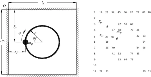
In order to examine the effect of the mass that moves in an orbit on the plate, a square thin plate with all edges meeting CCCC conditions as well as with lx ly 1 m dimensions and h 0.01 m
thickness values was chosen. Other properties of the plate are identical to the previous plate. The damping matrix C of the whole system was calculated with equations (23 and 24) by using the
damping ratios of 1 0.005 and 2 0.006 (which c”rresp”“d t” the system’s “atural freque“cies
1, 2). Figure 4 shows a square CCCC plate which carries a mass with an angular velocity of at a circular path with a radius of r. The plate was divided into plate elements that it consists of
121 elements and 144 nodes with 11X11 meshing. The Cartesian coordinate system of the plate was
placed at such a location where left edge and back edge combine at x 0, y 0, O point and the
middle point of plate thickness is z 0 and downward positive. Local coordinates of the plate ele-ments were located at the left back corner similar to the plate. Global xp t and yp t coordinates
of the mass on plate were evaluated depending on the coordinate system as well as the element on which the mass is located during motion, whereas local xm t , ym t coordinates are evaluated
depending on the local coordinate system.
Starting position of the mass is the point where θ angle on the trajectory is zero; the motion of the mass is clockwise with constant angular velocities. Scalar value of the tangential velocity of the mass is constant but the direction of the velocity is constantly changing; therefore, a centripetal acceleration affects the mass towards the central point of the trajectory. At any θ angle, the global coordinate of the mass on the plate and its local coordinate on the element are calculated with Eq. (20). The number of the element which hosts the mass is determined by matrix mapping algorithm also given in Eq. (20). Angular vibration frequencies at the first four vibration modes of the chosen plate are 1 567.0254 rad/s, 2 3 1154.3784 and 4 1720.3322 rad/s. Analysis is
con-( ) ( )
Latin A m erican Journal of Solids and Structures 12 (2015) 808-830
ducted separately for constant angular velocities of the mass during one tour and in a certain time period (75T1), where T1 is the period of the first fundamental vibration mode.
r
xp
yp
mp
l
l
O x
y
mp
1
2
3
11 12
41 29 28 27 38
37 48 47 58 69
70 81
82 93
94
95 84
85
75 64 53 52 40
74
22 33 99 110
23 34 45 56 67 78 89 100
10 9
4
5 6
8 7
yp
xp
Figure 4: A CCCC plate with an orbiting mass that moves on a circular path with a radius of r and at an angular velocity of .
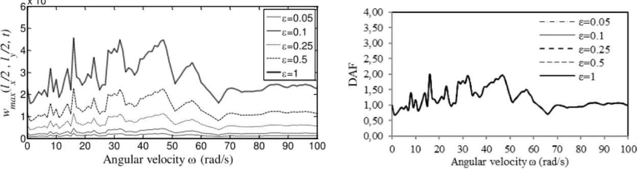
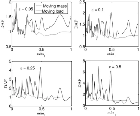
For mass ratios 0.05, 0.1, 0.25, 0.5 and 1, the behaviour of the plate at different angular velocities and different trajectory radiuses is shown with graphics. The mass ratio is defined by ratio of the mass of the moving load to the mass of the plate. Figure 5 shows the dynamic deflec-tions of the central point of the plate in one-tour motion situation of the masses with 0.05, 0.1, 0.25 mass ratios at a circular trajectory of radius r 0.25 m, which angular velocity starts at 1 up to 100 rad/s with increments of 1 rad/s. These deflections are defined as the ratio of maximum values of the absolute time-dependent deflections of the central point of the plate as DAF = max lx 2,ly 2,t st lx 2,ly 2 to the deflections that the mass would have generated if it had
remained static at the central point of the plate. The amount of deflection that will be created by a static force at the central point of the thin plate under a square CCCC boundary conditions can be
calculated with 2, 2 0.061 2 3
st lx ly m glp x Eh formula, Clough and Penzien (2003). The mass
of the plate is 78.5 kg; moving mass is 3.925 kg, 7.85 kg 19.625 kg, 39.25 kg and 78.5 for 0.05, 0.1, 0.25, 0.5 and 1, respectively.
0 10 20 30 40 50 60 70 80 90 100
0 1 2 3 4 5
Angular velocity (rad/s)
DAF
=0.05
=0.1
=0.25
Figure 5: Angular velocity-dependent dynamic behaviour of maximum deflections that develop at the central point of the plate in case of motion with various mass ratios of the mass at circular orbit with r 0.25 m, DAF (dynamic
amplification factors).
( ) ( )
Latin A m erican Journal of Solids and Structures 12 (2015) 808-830
Close examination of Figure 5 shows no considerable increase in deflection on the plate in masses with relatively low mass ratio, i.e. 0.05 and 0.1. DAFs obtained in the given velocity interval are usually under 2 and fluctuate between 0.75 and 2, depending on the angular velocity of the mass. Nevertheless, when the mass ratio is 0.25, DAF considerably increases at some angular rotation velocities. Maximum DAF is obtained as 4.3 at 30 rad/s velocity. The second highest DAF is witnessed as 3.82 at 9 rad/s velocity. The analyses here are conducted basing on one rotation of the mass, and the results show the transient effect of the mass. What kind of dynamic behaviour can be witnessed in the plate in case of a continuous effect posed by the mass at a con-stant angular velocity? Analyses results for this question will be provided below.
In Figure 6 the absolute deflections that are generated due to the assumption that the mass is a moving load. If the graph is examined carefully it can be seen that the graphs occur identical for all mass ratios in the case that each graph is given as DAF. It is seen that maximum DAF occurs at around 2 at 16, 32 and 48 rad/s angular rotation velocities at the orbit. This is no surprise as it is the result of the fact that neglects the inertia effects of the mass due to moving load assumption. These graphs once more tell that moving load approach is rather inadequate for reflecting the real behaviour of the plate. Nevertheless, at relatively smaller mass ratios, i.e. 0.05 and 0.1 (Figure 7), it should be noted that considerable differences do not develop between moving mass and mov-ing load assumption.
0 10 20 30 40 50 60 70 80 90 100
0 1 2 3 4 5 6x 10
-4
Angular velocity (rad/s)
w max
(
l x
/2
,
l y
/2
,
t)
=0.05
=0.1
=0.25
=0.5
=1
Figure 6: In the case of moving load assumption, absolute maximum deflections and DAF (dynamic amplification factors) that develop at the central point of the plate in the case of motion of the mass at various velocities and mass
ratios at circular r 0.25 radius.
Latin A m erican Journal of Solids and Structures 12 (2015) 808-830
shows almost minimum DAF at all mass ratios. This velocity is chosen in order to see the plate behaviour at different radius travels.
0 20 40 60 80 100
0 1 2 3
DAF
= 0.05
0 20 40 60 80 100
0 1 2 3
= 0.1
0 20 40 60 80 100
0 2 4 6
Angular velocity (rad/s)
DAF
= 0.25
0 20 40 60 80 100
0 20 40 60
Angular velocity (rad/s) = 0.5
Moving mass Moving load
Figure 7: DAFs of absolute deflections formed on the plate by a mass moving at angular velocities 1-100 rad/s and r 0.25 m rotation radius, depending on mass ratios;
solid line is for moving mass and dotted line is for moving load.
0 0.1 0.2 0.3 0.4 0
1 2 3
DAF
= 0.05
0 0.1 0.2 0.3 0.4 0
1 2 3
4 = 0.1
0 0.1 0.2 0.3 0.4 0
5 10 15
Radius r (m)
DAF
= 0.25
0 0.1 0.2 0.3 0.4 0
100 200 300 400
Radius r (m) = 0.5
=30 rad/s
=88 rad/s
Figure 8: DAFs of central point of the plate versus rotation orbit radius r when the mass moves with 30 and 88 rad/s, for mass ratios of 0.05, 0.1, 0.25 and 0.5.
Latin A m erican Journal of Solids and Structures 12 (2015) 808-830
at some radiuses at bigger mass ratios such as 0.25 and 0.5. For 0.25 mass ratio, the radiuses of
r 0.32 and 0.40m and even 0.46m, which is very cl”se t” the edge ”f the plate, a“d f”r ε =0.5
mass ratio, the radiuses of r 0.32 and 0.40, are considered highly risky. At 30 rad/s rotation
velocity, r 0.3 and 0.37 m radiuses for 0.05 mass ratio, r 0.23 m radius for 0.1 mass ratio, r 0.14 radius for 0.25 mass ratio and r 0.26, r 0.35 and r 0.40 m radiuses for 0.25 m and
0.5 mass ratios are rotation radiuses where DAF reaches its peak. From these results, it can be concluded that a rotation velocity and mass ratio which is reliable for one radius will not necessarily be reliable for another radius.
Figure 9 presents the behaviour of a plate depending on mass ratios which are at a certain radius orbit, at 30 rad/s velocity and at a definite period of travel, i.e. t 75T1, r 0.375 m, where
the mass takes 4 tours a second at its orbit on the plate in t 0.837758 seconds. At mass ratios of
0.05 and 0.25, deflections of the plate are small and stable, whereas at 0.1 deflections tend to in-crease slowly and constantly; at 0.5 and 1 mass ratios deflections tend to inin-crease rapidly. Figure 10 gives the change generated by the effect of constant mass ratio 0.5 at 30 rad/s velocity for moving mass and load assumption. As for motion at r 0.125 motion orbit radius, deflections
de-crease in time, whereas they constantly and slowly inde-crease at 0.25 radius; they tend to inde-crease rapidly at 0.375 and 0.475 m and change the plate stability. Thus, it can be observed that the de-signs should take continuity of motion on orbit into consideration. So much so that if the plate is subjected to constant interaction with the mass at an angular velocity that corresponds to a very small peak, resonance will develop albeit slowly after some time as Figs. 9 and 10 show.
0 0.2 0.4 0.6 0.8
-2 -1 0 1 2 3x 10
-5
w z
(
l x
/2
,
l y
/2
,
t)
= 0.05
0 0.2 0.4 0.6 0.8
-5 0 5 10x 10
-5 = 0.1
0 0.2 0.4 0.6 0.8
-4 -2 0 2 4 6x 10
-5
Time t (sec). w z
(
l x
/2
,
l y
/2
,
t)
= 0.25
0 0.2 0.4 0.6 0.8
-0.04 -0.02 0 0.02 0.04
Time t (sec). = 1
Figure 9: For an excitation period of 75T1, deflections of the central point of the plate for orbiting radius
Latin A m erican Journal of Solids and Structures 12 (2015) 808-830
0 0.1 0.2 0.3 0.4 0.5 0.6 0.7 0.8
0 1 2
x 10-4
Time t (sec).
w z
(
l x
/2
,
l y
/2
,
t) = 0.5, =30 rad/sec., r=0.125 m.
0 0.1 0.2 0.3 0.4 0.5 0.6 0.7 0.8
-1 -0.5 0 0.5
1x 10 -3
Time t (sec).
w z
(
l x
/2
,
l y
/2
,
t) = 0.5, =30 rad/sec., r=0.25 m.
Moving mass Moving load
Moving mass Moving load
0 0.1 0.2 0.3 0.4 0.5 0.6 0.7 0.8
-0.04 -0.02 0 0.02 0.04
Time t (sec).
w z
(
l x
/2
,
l y
/2
,
t) = 0.5, =30 rad/sec., r=0.375 m.
0 0.1 0.2 0.3 0.4 0.5 0.6 0.7 0.8
-2 -1 0 1 2 3x 10
-3
Time t (sec).
w z
(
l x
/2
,
l y
/2
,
t) = 0.5, =30 rad/sec., r=0.475 m.
Moving mass Moving load
Moving mass Moving load
Figure 10: Deflections of the central point of the plate for: 0.5, 30 rad/s., r 0.125, 0.25, 0.375, 0.475 m.
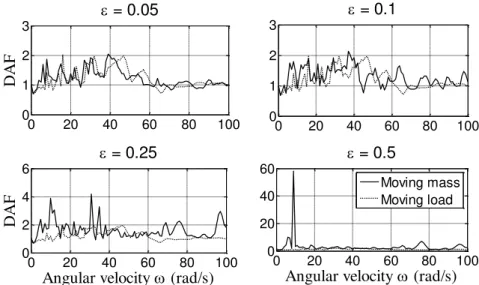
Figure 11 gives the situations that examine the behaviour of the plate in the interval until the angular frequency of the first fundamental vibration mode at very high angular velocities, i.e. 1 576.0254 rad/s, at an orbit with a certain radius on the plate.
ap-Latin A m erican Journal of Solids and Structures 12 (2015) 808-830
proaches yield similar results. For this reason, at very small mass ratios and rotation velocities, moving load approach can be used for those who want to get quick results. However, as the angular velocity increases, graphs change differently. It can be seen that, for all mass ratios, graphs yield many huge or small peaks at different velocities. With more precision, analysis results for orbit ra-dius of r 0.25m with 1 rad/s increments, from 1 to 577 rad/s and 0.25 mass ratio are
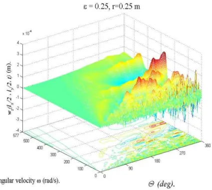
provided in Figure 12 in 3-d fashion. For the mass ratio of 0.25 and rotation orbit radius of
r 0.25 m, deflections of the central point of the plate are given in Figure 12 depending on the θ
angle at which the mass is located on the plate and the angular velocity of the mass, where the vertical axis shows the real deflections of the central point of the plate, and horizontal x and y axes show the angular velocity of the mass according to the position angle of the mass as per the refer-ence system. When Figure 12 is examined in detail, it can be seen that θ angles with high deflection values are mostly bigger than 180 degrees, because when the mass is rotating on the plate, the vi-bration velocity and acceleration of the plate system increases due to the mass motion.
0 0.5 1
0.5 1 1.5 2
/
1
DAF
= 0.05
0 0.5 1
0.5 1 1.5 2 2.5
/
1
DAF
= 0.1
0 0.5 1
0 1 2 3 4 5
/
1
DAF
= 0.25
0 0.5 1
0 2 4 6 8
/1
DAF
= 0.5 Moving mass
Moving load
Figure 11: DAFs of central point for 1 0.1-1, orbiting radius r 0.25 m, 0.05, 0.1, 0.25, 0.5, moving mass and moving load cases.
In real engineering systems, the effects of these parameters have to be controlled with very small changes in the planned working interval of the system taking into consideration the rotation veloc-ity, mass ratio and rotation radius of the designed system. Otherwise, the system can be risked if one parameter that can create resonance in the system is gone unnoticed.
ap-Latin A m erican Journal of Solids and Structures 12 (2015) 808-830
proximately 0.52 1 and higher, deflections that develop with the impact of high velocity and mass
decrease as [c] and [k] matrixes repress the motion-equation of the plate. Despite all this difficul-ties, each mass ratio has a reliable orbiting radius and rotation velocity and each orbiting radius and rotation velocity has a mass ratio with which motion can be constantly ensured without chang-ing the stability of the plate mass system. In practical design, the method recommended in this paper can be applied to easily determine the other reliable parameters depending on a certain pa-rameter. For example, as can be seen in Figure 9, r 0.375 m looks reliable for this plate with
30 rad/s, 0.05, 0.25 values. In Figure 10, the rotation radius of r 0.125 m is reliable
for 0.5, 30 rad/s, whereas in Figure 8, all radiuses under r 0.2 m are reliable.
Figure 12: Deflections of the central point of the plate at 0.25 mass ratio and r 0.25 rotation orbit radius depending on the θ angle with which the mass is located on the plate a“d ω a“gular speed ”f the mass.
The longitudinal deflections of the contact point in x and y directions due to centrifugal
accel-eration of the moving mass are given in Figure 13, for 0.25, r 0.25 m and constant angular
velocities of 10, 30 and 90 rad/s, depending on dimensionless position ( t 2 ) of the rotating mass around the circular path. The black lines are for direction x, while the red ones are for direction y.
When the Figure 13 is examined closely, especially for higher angular velocities the longitudinal deflections of the may increase to a significant level in terms of the strength of the plate. Since the studied plate is square and isotropic, the maximum deflection for both x and y directions is
0.002972 mm; but due to rotation of the mass there is a phase angle of 90 degrees between the x
and y deflections as shown from Figure 13. As another result, one can estimate that the
Latin A m erican Journal of Solids and Structures 12 (2015) 808-830 Figure 13: For angular velocities of 10, 30 and 90 rad/s, the longitudinal x and y deflections of
the contact point of the plate at 0.25 mass ratio and r 0.25 m rotation orbit radius depending on the dimensionless position ( t 2 ).
4 CONCLUSIONS
Equation of motion of a thin rectangular plate under the excitement of a moving mass has been derived representing all effects of the mass by taking into consideration the in-plane and out of plane acceleration components of the mass. In the finite element model of the equation of motion, the inertia effects induced by moving mass have been integrated to the system by deriving time-dependent equivalent mass [m], damping [c] and stiffness [k] matrices which represent the inertia force, the Coriolis and centrifugal force components, respectively. As an alternative to the analytical methods which are disadvantaged due to the fact that it is almost impossible to reach a solution taking into consideration inertia effects, damping and variable mass velocities in plate systems un-der the effect of a mass that moves on variable passage paths, the author presented a method that takes into account effects discarded in the moving FORCE model. The proposed method can be used for the calculation of the dynamic behaviour of moving mass-plate system along with variable mass-travelling velocities and all effects of the mass and vibration damping effects of the system for various mass trajectories and which can be easily implemented by adapting to the classical FEM method.
For the orbiting motion, it has been indicated that, besides the size and angular velocity of the mass, the radius of the orbit is also an essential factor in behaviour of the plate. Moreover, it has been shown that larger masses rapidly decrease the resonance excitation frequency. The changes in orbiting motion of continuous rotating for time t 75T1 s have been simulated, and it has been
Latin A m erican Journal of Solids and Structures 12 (2015) 808-830
at selected mass size, rotation angular velocity and determined orbit radius parameters. Despite the non-linear behaviour of the system in orbiting motion, each mass ratio has a reliable orbiting radius and rotation velocity, and each orbiting radius and rotation velocity has a mass ratio with which motion can be constantly ensured without changing the stability of the plate mass system.
The most important one of the few parameters that administers the general behaviour of the plate is the change in vibration frequency of the system depending on the size and position of the mass on the plate. In orbiting motion, there are some additional factors such as the effect of veloc-ity, deflexion of the velocity vector with the effect of centripetal acceleration, and positive or nega-tive signs of the components of tangent velocity at some mass contact angles depending on the plate coordinate system. All these impacts non-linearly affect motion equations and the behaviour of the system. In practical design, other reliable parameters can be easily determined depending on a cer-tain parameter applying the method recommended in this study.
Acknowledgements
The author acknowledges Sabriyaman Inc. (Manufacturer of wood working machineries in Istanbul, Turkey) for all supports to the present research.
References
Amiri, J.V., Nikkhoo, A., Davoodi, M.R., Hassanabadi, M.E., (2013). Vibration analysis of a Mindlin elastic plate under a moving mass excitation by eigenfunction expansion method. Thin Wall. Struct. 62: 53-64.
Awodola, T.O., (2014). Flexural motions under moving concentrated masses of elastically supported rectangular plates resting on variable winkler elastic foundation. Latin American Journal of Solids and Structures11(9): 1515-1540.
Bachmann, H., (1995). Vibration Problems in Structures. Birkhauser Verlag, Berlin.
Bathe, K.J., (1982). Finite element procedure in engineering analysis. Prentice-Hall, New Jersey.
Cifuentes, A., Lalapet, S., (1992). A general method to determine the dynamic response of a plate to a moving mass. Comput. Struct. 42: 31-36.
Clough, R.W., Penzien, J., (2003). Dynamics of structures, 3rd ed. Computers and Structures, Inc., California. Eftekhari, S.A., Jafari, A.A., (2012). Vibration of an initially stressed rectangular plate due to an accelerated travel-ling mass. Sci. Iran A 19(5): 1195-1213
Ese“, İ., (2011). Dy“amic resp”“se ”f a beam due t” a“ accelerati“g m”vi“g mass usi“g m”vi“g fi“ite eleme“t a p-proximation. Math. Comput. Appl. 16(1): 171-182.
Ese“, İ., (2013). A “ew fi“ite eleme“t f”r tra“sverse vibrati”“ ”f recta“gular thi“ plates u“der a moving mass. Finite Elem. Anal. Des. 66: 26-35
Faria A.R., Oguamanam, D.C.D., (2004). Finite element analysis of the dynamic response of plates under traversing loads using adaptive meshes. Thin Wall. Struct. 42: 1481-1493.
Fayaz R.R., Nikkhoo, A., (2009). Application of active piezoelectric patches in controlling the dynamic response of a thin rectangular plate under a moving mass. Int. J. Solids Struct. 46: 2429-2443.
Fryba, L., (1999). Vibrations of the Solids and Structures under Moving Loads. Thomas Telford Publishing House, London.
Latin A m erican Journal of Solids and Structures 12 (2015) 808-830 Gbadeyan, J.A., Oni S.T., (1995). Dynamic behaviour of beams and rectangular plates under moving loads. J. Sound Vib. 182 (5): 677-695.
Gerdemeli, İ., Ese“, İ., Özer, D., (2011). Dynamic response of an overhead crane beam due to a moving mass using moving finite element approximation. Key. Eng. Mat. 450: 99-104.
Ghafoori, E., Asghari, M., (2010). Dynamic analysis of laminated composite plates traversed by a moving mass based on a first-order theory. Compos. Struct. 92(8): 1865-1876.
Kadivar, M.H., Mohebpour, S.R., (1998). Finite element dynamic analysis of unsymmetric composite laminated beams with shear effect and rotary inertia under the action of moving loads. Finite Elements in Analysis and Design. 29: 259.
Lee, H.P., (1996). Transverse vibration of a Timoshenko beam acted upon by an accelerating mass. Appl. Acoust. 47(4): 319-330.
Lee, U., (1998). Separation between the flexible structure and the moving mass sliding on it. J. Sound Vib. 209(5): 867-877.
Mamandi, A., Kargarnovin, M.H., Farsi, S., (2010). An investigation on effects of travelling mass with variable veloc-ity on nonlinear dynamic response of an inclined Timoshenko beam with different boundary conditions. Int. J. Mech. Sci. 52: 1694-1708.
Meirovitch, L., (1967). Analytical methods in vibrations. The Macmillan Company. New York.
Mohebpour, S.R., Malekzadeh, P., Ahmadzadeh, A.A., (2011). Dynamic analysis of laminated composite plates sub-jected to a moving oscillator by FEM. Composite Structures 93: 1574–1583.
Nikkhoo, A., Fayaz R.R., (2012). Parametric study of the dynamic response of thin rectangular plates traversed by a moving mass. Acta Mech. 223: 15-27
Oni, S.T., Awodola, T.O., (2011). Dynamic behaviour under moving concentrated masses of simply supported rec-tangular plates resting on variable Winkler elastic foundation. Latin American Journal of Solids and Structures 8: 373-392.
Reddy, J.N., (1984). Energy and variational methods in applied mechanics. John Wiley and Sons, New York. Shadnam, M.R., Mofid, M., Akin, J.E., (2001). On the dynamic response of rectangular plate, with moving mass. Thin Wall. Struct. 39: 797-806
Sharbati, E., Szyszkowski, W., (2011). A new FEM approach for analysis of beams with relative movements of masses. Finite Elem. Anal. Des. 47: 1047-1057
Szilard, R., (2004), Theories and Applications of Plate Analysis. Wiley, New Jersey.
Taheri, M.R., (1987). Dynamic response of plates to moving loads, structural impedance and finite element methods, Ph.D. Dissertation, Purdue University, IN.
Wang ,Y.M., (2009). The transient dynamics of a moving accelerating/decelerating mass travelling on a periodic-array non-homogeneous composite beam. Eur. J. Mech. A-Solid 28: 827-840.
Wilson, E.L., (2002). Static and Dynamic Analysis of Structures, Chapter 20: Dynamic analysis by numerical inte-gration, Computers and Structures Inc., California.
Wu, J.J., (2005). Dynamic analysis of a rectangular plate under a moving line load using scale beams and scaling laws. Comput. Struct. 83: 1646-1658.
Wu, J.J., (2007). Vibration analyses of an inclined flat plate subjected to moving loads. J. Sound Vib. 299: 373-387. Wu, J.J., Whittaker, A.R., Cartmell, M.P., (2001). Dynamic responses of structures to moving bodies combined finite element and analytical methods. Int. J. Mech. Sci. 43: 2555-2579.
Yang, T.Y., (1986). Finite Element Structural Analysis. Prentice-Hall, New Jersey.
Latin A m erican Journal of Solids and Structures 12 (2015) 808-830
APPENDIX A. Derivation procedures of Eqs. (3.b)
Since the longitudinal deflections of the plate are very small when compared with the vertical de-flections. The contact forces in x and y directions Fx and Fy are
2 2
2 2
d ( , , ) d ( , , )
( ( )), ( ( ))
d d
x p p y p p
x p p y p p
w x y t w x y t
F m x x t F m y y t
t t
where wx x y tp, p, and wy x y tp, p, , respectively, represent the longitudinal x and ydisplacements at positions xp, yp and time t. In this case for the longitudinal x vibration of the plate one can obtain the following equations:
d ( , , ) ( , ) ( , )
0 0 ( , ) ( , ) ( , )
d
x p p x x
x x x
w x y t w x t x w x t t
w x t x w x t w x t
t x t t t (A1)
2
2
d ( , , ) ( , ) ( , )
0 0 ( , ) ( , ) ( , )
d
x p p x x
x x x
w x y t w x t x w x t t
w x t x w x t w x t
x t t t
t (A2)
For the longitudinal y vibration of the plate one can:
d ( , , ) ( , ) ( , )
0 0 ( , ) ( , ) ( , )
d
y p p y y
y y y
w x y t w y t y w y t t
w y t y w y t w y t
t y t t t (A3)
2
2
d ( , , ) ( , ) ( , )
0 0 ( , ) ( , ) ( , )
d
y p p y y
y y y
w x y t w y t x w y t t
w y t y w y t w y t
x t t t
t (A4)
APPENDIX B. Shape functions of the plate element in Eq. (7).
1 1 1 2 3 4 2 1 5 1 2
6 2 2 7 1 3 8 9 10 2 3
11 1 4 12 2 4 13 3 3 14 15
16 4 3 17 3 4 18 4 4 19 3 1
20 21
, (1 ( ))(1 ( )), , ,
, , ( )(1 ( )), ,
, , , = ( ) ( ),
, , , ,
= = ( )(1
p q t t p q p q
p q p q t t p q
p q p q p q t t
p q p q p q p q
t ( )), t 22 p q4 1, 23 p q3 2, 24 p q4 2
(B1)
With,
2 3 2 3
1 2
2 3 3 2
3 4
2 3 2 3
1 2
2 3 3 2
3 4
1 3 ( ) 2 ( ) , [ ( ) 2 ( ) ( ) ],
3 ( ) 2 ( ) , [ ( ) ( ) ]
1 3 ( ) 2 ( ) , [ ( ) 2 ( ) ( ) ]
3 ( ) 2 ( ) , [ ( ) ( ) ]
( ) ( )
( ) m , ( ) m
p t t p a t t t
p t t p a t t
q t t q b t t t
q t t q b t t
x t y t
t t
a b
(B2)
Latin A m erican Journal of Solids and Structures 12 (2015) 808-830
where pn and qn (n 1, 2, 3, 4 ) are hermitical polynomial components that represent plate shape functions in x and y-axes respectively. The symbols a and b are the length and width of kth plate
element respectively, whereas xm t and ym t are variable distances between the moving mass and the left end-local coordinate of the kth plate element, at time t, as shown in Figure (2).