Experimental vibration analysis for a 3D scaled model of a
three-floor steel structure
Abstract
In this paper we present an experimental study of a three dimensional physical model of a three-floor structure sub-jected to forced vibrations by imposing displacements in its support. The aim of this work is to analyze the behavior of the building when a dynamic vibration absorber (DVA) is acting. An analytic simplified analysis and a numerical study are developed to obtain the natural frequencies of the structure. Experiments are carried out in a vibrating table. The frequency range to be experimentally analyzed is de-termined by the first natural frequency of the structure for which the DVA damping effects are verified. The equipment capabilities, i.e. the frequencies, amplitudes and admissible load, limit the analyses. Nevertheless, satisfactory results are obtained for the study of the first mode of vibration. The effect of different amplitudes of the imposed support motion is also analyzed. In addition, the damping effect of the DVA device is evaluated upon varying its mass and its location in the structure. The characteristic curves in the frequency domain are obtained computing the Fast Fourier Transformation (FFT) of the acceleration history registered with piezoelectric accelerometers at different checkpoints for the cases analyzed.
Keywords
Dynamic Vibration Absorber, first mode of vibration, am-plitude reduction, forced vibration, structural resonance.
Ernesto F. Castillo and Marcela A. Cruchaga∗
Department of Mechanical Engineering, Uni-versidad de Santiago de Chile
Av. Lib. Bernardo O‘Higgins 3363, Santiago, Chile
Received 27 Mar 2012; In revised form 12 May 2012
∗Author email: [email protected]
1 INTRODUCTION
situations in which it is possible to reduce, but not to eliminate the dynamic forces that excite a system inducing a vibratory behavior on it. Loads produced by an earthquake or by wind are unpredictable variables that subject structures to variable dynamic loads. The resulting displacements damage the structure and, in many cases it could not be restored. These reasons make the study of vibrations in structures and the control of their behavior under dynamic loads an interesting study.
There are basically four fundamental mechanisms of vibration control [2, 4, 6, 8, 18, 22, 24], which are: control of the natural frequencies in order to avoid resonance under external imposed loads, introduction of damping or any energy spendthrift mechanism, use of insulating elements in supports and/or bases that reduce force transmission, and the incorporation of dynamic vibration absorbers or vibration neutralizers.
Several dynamic absorbers have been designed; some of them are based on the impact of a mass on the structure (IVA) [8], while others are used in aeronautical applications to minimize vibration and noise levels in the piloting cabin [13]. Many absorbers have been built to control wind [9] or seismic effects [11, 16] on structures. This last field becomes very important nowadays from the safety perspective in the increasingly more daring architectural engineering works. Chen et al. [5, 23] have carried out several contributions in structures damping and anti-seismic construction. Their experimental and numerical studies developed both for buildings and in transportation applications, are outstanding. These studies optimize construction through elements of seismic control, thus improving road safety.
A different approach consists of introducing materials with vibrations absorbing capacity in the same structure. Park and Palumbo [18] study the behavior of different sizes of polyamide granules in sandwich beams, obtaining reduction in the vibratory responses without increas-ing structural weight or stiffness. Chiba and Furukawa [6] propose to insert fine sheets of polyamide into the structural parts, increasing in this way the structural damping without large modifications on dimensions and weight of such parts.
The dynamic absorbers can be classified as active or passive depending on their opera-tional principle. Active ones require an external source that controls their operation, generally a servomechanism. Passive ones work autonomously responding to the system excitement it-self, being limited to a specific frequency inhibition. Through the years, different types of absorbers have been created. Some of them use viscous damping generated by fluids motion [10, 24], meanwhile others act mechanically using a mass-spring damper system [22]. There are also some absorbers designed to operate based on the movement of a pendulum attached to the structure [2]. Fischer[9] evaluates the efficacy of the pendulum and ball type absorbers comparing their behavior in different structures with those obtained using viscous type ones.
The composed IVA controls vibrations better, being this one the option recommended by the authors.
Pham et al. [20], implement a non-linear dynamic vibration absorber (DVA) to suppress the first mode of resonance of a structure with two degrees of freedom. The nonlinear DVA acts not only in a preferential frequency, thus it is possible to capture multiple resonance modes. The mass, damping, and stiffness matrices are derived applying Newton’s second law. To solve the derived matrix system of equations, the authors propose and asymptotic expansion of the unknowns based on the approach proposed by Manevitch [17] assuming that the nonlinear coupling does not change the eigenmodes of the main system. The authors compare analytic results with the numerical ones, obtaining a good correlation between them which validates the proposed analytical method.
In different industrial applications, cantilever beams are subjected to dynamic loads that can reduce its operative life by vibratory effects. Bonsel et al. [4] investigate the use of a linear damped and a non-damped DVA device applied to a vibratory system. The system was built using a beam that support an unbalanced engine rotating to a constant speed of 60 rpm giving as a result a pulsating sinusoidal load. After carrying out numerical simulations and experimental analysis, these authors concluded that both devices, the dumped and the non-damped absorbers, have similar responses for the suppression of the first mode of vibrations, as well as other sub-harmonic modes found.
A dynamic vibration absorber is tuned to a specific mode of vibration of a system. Ji and Zhang [14] analyze the implementation of a dynamic linear absorber on a non-linear mass-spring-damping system. The authors evaluate the dynamic response in primary resonance with and without DVA. For small-amplitude excitation in the resonance range, large ampli-tudes in the response of the system without DVA are observed. After adapting the absorber, the magnitude of displacement is considerably reduced showing the efficiency of this type of mechanisms for vibratory control. A standard DVA is composed by a mass, a spring and a damper. The authors analyze the system modifying the mechanical characteristics of the DVA, showing that the size of the vibrations neutralizer can be considerably smaller than the original structure when a correct optimization of the device parameters is done.
measurements.
As it was already commented, during the experiments, the structure is subjected to cyclic displacements using different frequencies and two motion amplitudes. The acceleration is reg-istered at different control points of the structure using piezoelectric accelerometers. The ac-celeration signals are treated through FFT in order to obtain their description in the frequency domain. The structural behavior is evaluated under the imposed displacement and when a mass-spring dynamic absorber is incorporated. The characteristic curves of acceleration vs. imposed frequency are obtained for the structure without and with DVA, characterizing the resonance in the first mode of vibration and tuning the DVA to this primary frequency. More-over, the sensitivity of the responses to the imposed amplitudes of the support motion is also analyzed. On the other hand, the effect of the DVA location is also evaluated.
In Section 2, the dimensional analysis, the analytic calculation and the numerical model are briefly presented. The structure is reduced to a system of three degrees of freedom [3] con-centrating masses through Rayleigh’s method [21]. The analytic results are obtained through a simplified approximation based on the mass and stiffness matrix method [19]. Further de-tails could be found in the referred works and in the section below. In Section 3 we present the experimental lay out and the measurements registered for different imposed frequencies and amplitudes’ motion when the structure is analyzed without and with DVA evaluating its effects in vibration control at primary resonance. A complementary analysis on the effect of the absorber position is also presented. Section 4 presents the analysis and discussion of the experimental results obtained in this study. Finally, the conclusions are summarized.
2 SIMPLIFIED MODELS
2.1 Dimensional analysis
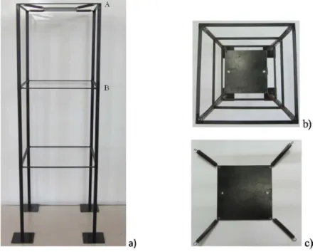
Geometry and construction details of the steel structure used in this study are shown in Figure 1. It represents a three-level building of square section supported by columns. The bench-scale structure has the following dimensions: A = 350 mm and H = 1050 mm being the wide and total height of the structure, respectively; ab = 15 mm and eb = 3 mm being the height and
thickness of the beams delimiting the floors of the building; hc = 350 mm, ac = 15 mm, bc
= 13 mm and ec = 1 mm being the height, the outer and inner edges and the thickness of
the column of square section, respectively. This physical model could represent a prototype building made of the same material, i.e. the density (ρ) and Young modulus (E) do not vary. In the present analysis, the properties for the structural steel are taken as: ρ = 7850 kg/m3
andE = 200 GPa. With these considerations and assuming a defined length scaleEL= Lp/Lm
(being Lp a characteristic prototype length and, Lm the correlated length in the model) the scales of mass (EM), inertia (EI), stiffness (ES) and frequency (Ef) are powers of EL as it is
shown in Table 1. The total mass of the model ismT = 3 kg,hence, as example, a prototype of
approximatelymT = 1000 kg,A = 3 m,H = 7 m andac = 0.1 m could be represented by the
model (resultingEL= Lp/Lm= 6.67). The dimensional analysis could require additional work
results summarized in Table 3 validate the assumed scales.
Table 1 Analysis of scales.
Magnitude Unites Scales (Prototype/Model)
Length [L] EL
Mass [M]=[ρ][L]3
EM =EL 3
Inertia [I]=[L]4
EI =EL4
Stiffness [K]=[E][I][L]−3
ES =EL
Frequency [f]=
√
[E][I][L]−3
[ρ][L]3 Ef =EL− 1
The utilized dynamic vibration absorber is a mass-spring type and it is also shown in the Figure 1. The DVA is made of four equal stiffness springs and a steel plate. Plates of different masses (m1 = 0.78 kg andm2 = 0.64 kg, wheremiis the steel plate mass of the DVA) and two
DVA positions (top or third floor and second floor, where point A and point B are respectively located) are also studied.
Figure 1 Analyzed structure: a) overall view; b) view from the top; c) DVA configuration
2.2 Calculation of the vibration modes
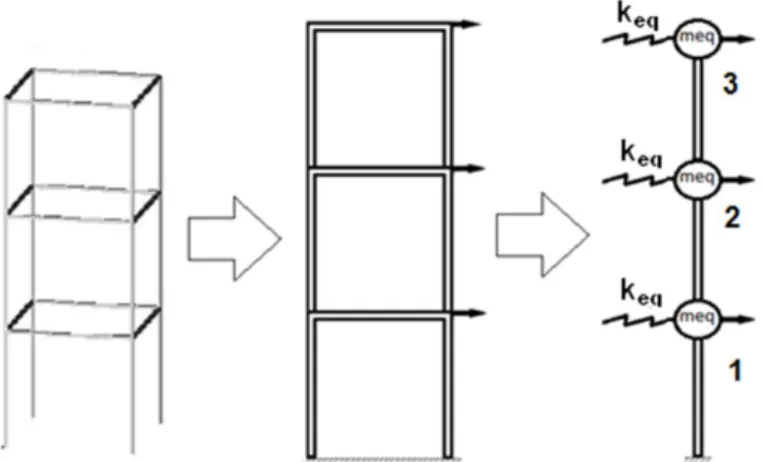
The analytic model used to estimate vibration modes of the proposed structure is a simpli-fication of the continuous three-dimensional prototype. The structure is reduced to a plane mass-spring model whose components are detailed in Figure 2.
Figure1, cont. Analyzed structure: d) geometry in mm.
MX¨+SX=Q (1)
where M, is the masses matrix,S stiffness matrix andQ the load vector, defined as follows:
M =⎡⎢⎢⎢
⎢⎢ ⎣
meq1 0 0
0 meq2 0
0 0 meq3
⎤⎥ ⎥⎥ ⎥⎥ ⎦
S=⎡⎢⎢⎢
⎢⎢ ⎣
2keq −keq 0
−keq 2keq −keq
0 −keq keq
⎤⎥ ⎥⎥ ⎥⎥ ⎦
Q=⎡⎢⎢⎢
⎢⎢ ⎣
Q1 Q2 Q3
⎤⎥ ⎥⎥ ⎥⎥ ⎦
(2)
The equivalent masses (meq) of the equation (2) are calculated applying Rayleigh’s theory
that allows concentrating masses of a continuous system minimizing error associated to it. Con-sidering the structure’s floor and the columns masses, called as mf loorand mcol, respectively,
the equivalent masses are obtained as:
meq1=mf loor+4mcol meq2=mf loor+4mcol meq3=mf loor+42/3mcol
(3)
The equivalent stiffness (keq) that appears in the equation (2) is calculated in relation to
the structural bending stiffness assuming that the floors are practically rigid [19], resulting as:
keq=∑
col
12EI h3 =4
12EI
Figure 2 Simplified plane structure used for the analytic analysis.
whereE is the elastic modulus,I is the second moment of the cross-sectional area (or moment of inertia) andh is the height of the column.
The frequencies (fi = √
λi, being λi the eigenvalues) and vibration modes (their related
eigenvectors,χ={χi}) of the problem are computed from the reduced system of equations (1)
assuming free vibrations (i.e., without external load Q) as follow:
(M−1S
−λI)x=0 (5)
Table 2 summarizes the analytic results obtained for frequency and eigenmodes (which are schematically represented in Figure 3.a). These values help to define the bench-scale model according to the capacity of the existing equipment.
Table 2 Analytic results.
Frequencies Model
f1(Hz) 9.214
f2(Hz) 25.394
f3(Hz) 35.742
2.3 3D - Numerical analysis of the structure
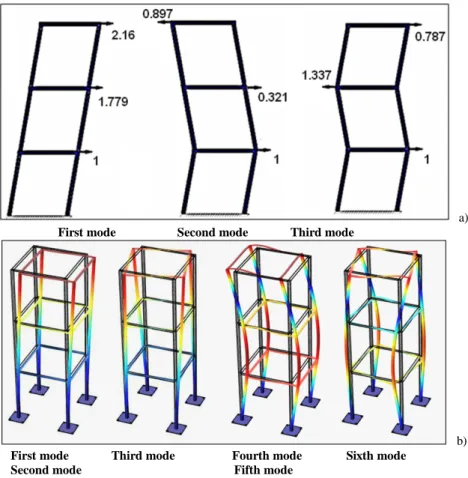
in Section 2.2, while the third and sixth modes that appear in the 3D numerical analysis can-not be represented for such a plane model. The differences between the frequencies computed using the plane and 3D models are also apparent. The fixing conditions used in the numerical analysis also affect the results. Nevertheless, low discrepancies can be found at the primary mode.
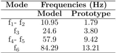
In addition, a numerical analysis was performed using the prototype geometry proposed in Section 2.1. The predicted natural frequencies are reported in Table 3. The frequency scale computed as Ef = fp/fm satisfy the relation (see Table 1) Ef =EL−1 = 1/6.67,
ap-proximately. These results confirm the capabilities of the physical model to predict structural natural frequencies.
Table 3 Numerically predicted vibration modes for the structure: model and prototype.
Mode Frequencies (Hz)
Model Prototype
f1- f2 10.95 1.79
f3 24.6 3.80
f4- f5 57.9 9.42
f6 84.29 13.21
2.4 Theory of the Dynamic Vibration Absorber (DVA)
As it is well known, a mechanical system may experience excessive vibration levels when it operates under the action of time depending loads with frequencies near their natural frequen-cies. A dynamic vibration absorber (DVA) is a mass-spring or mass-spring-damper type device added to the original structure. The basic theory of a DVA [7, 15] is deduced for an original mass (M1)-spring (K1) system which, subjected to the action of a harmonic force, experiences
displacement X 1(t) that is normally not admissible when the frequency of external force
ap-proaches to the system’s natural one. When adding mass M 2linked by a stiffness spring K 2
into the system, the modified structure has different natural frequencies and resonances could be avoided at the frequency of the imposed external force. The secondary M2- K2system has
as objective to distance the operational frequency from the original system’s natural frequency, consequently limiting displacements for an operational frequency range.
In this paper, the effectiveness of a mass-spring DVA is evaluated as well as its capacity to reduce accelerations at specific points of the structure when it is subject to oscillatory support displacements with different frequencies and amplitudes of excitation.
3 EXPERIMENTAL ANALYSIS
3.1 Experimental lay out
a) First mode Second mode Third mode
b) First mode Third mode Fourth mode Sixth mode
Second mode Fifth mode
Figure 3 Vibration modes for the structure: a) calculation as a simplified plane structure; b) three-dimensional numerical prediction.
cm, table peak velocity 84 m/s and table peak acceleration 24.5 m/s 2
. Preliminary to this work the shake table was calibrated and the natural frequencies of the vibrating table and its support where determined. The support of the table itself was designed to be rigid enough. The structure to be analyzed is fixed to the table and subjected to forced vibration applying periodic motions according to the described capacities of the shake table. The physical model is instrumented with piezoelectric accelerometers trademark Wilcoxon model 784A. It is a general purpose accelerometer with sensitivity of 100 mV/g and acceleration peak 50 g.
Figure 4 shows the experimental lay out. As it was already mentioned, the structure is tested without and with vibration absorbers of two different masses and positioned at different levels.
3.2 Free vibrations: determining vibration frequencies
Figure 4 Experimental lay out.
the range of frequencies to be experimentally analyzed setting the number of experiments to be carried out.
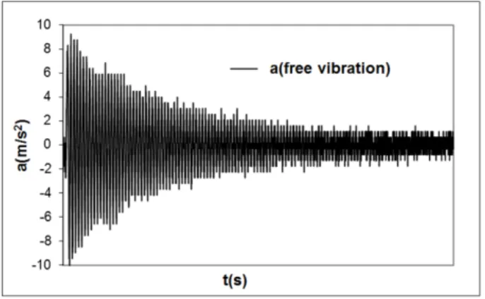
Free vibration is induced moving away the structure from its equilibrium position by ap-plying a quasi-static displacement at the top level. The evolution of the acceleration (referred asa from here onward) is registered using the accelerometers located at position A (see Figure 1.a). The structure is tested without and with DVA. Those signals are analyzed using a FFT to obtain the responses in the frequency domain. Figure 5 shows the signal captured without DVA (for simplicity, only this case is presented to illustrate the registered curves). Table 4 summarizes the FFT results for all tests performed. The analytic result (see Table 2) for the first natural frequency of the system without DVA reasonably predicts the obtained experi-mental frequency. The frequency analytically determined exhibits 8.5% of error relative to the experimental value.
Figure 5 Acceleration vs. time for the structure without DVA subjected to free vibration.
3.3 Forced vibration: structure behavior without DVA
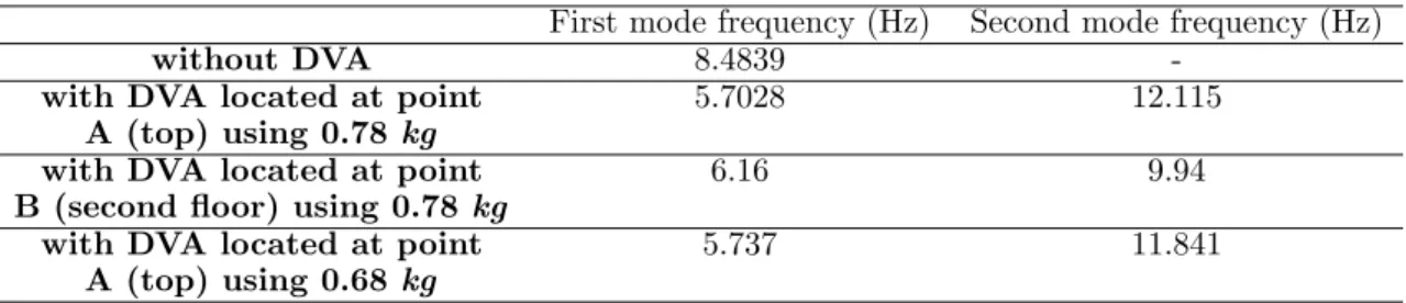
Table 4 Vibration modes obtained experimentally for the structure without and with DVA.
First mode frequency (Hz) Second mode frequency (Hz)
without DVA 8.4839
-with DVA located at point 5.7028 12.115
A (top) using 0.78 kg
with DVA located at point 6.16 9.94
B (second floor) using 0.78kg
with DVA located at point 5.737 11.841
A (top) using 0.68 kg
shake table using frequencies from 1 to 15 Hz and amplitudes of 1 and 2 cm for the imposed movement. The range of frequency covers the natural frequencies obtained in Section 3.2. The acceleration vs. time curves were registered using piezoelectric transducers at two positions: second and third floors. Following the same procedure described in the previous section to determine frequencies, the responses of the registered steady state signals are analyzed in the frequency domain obtained with the FFT. For external excitation of frequencies close to the own first natural frequency of the structure, the experiment cannot be performed due to the development of large displacements denoting resonance condition.
Figures 6 and 7 present the experimental results when testing the original structure with-out DVA. Each data point plotted are average value from measurements taken from three independent experiments performed under the same conditions, i.e. imposed frequency and amplitude as it is indicated in the plot. The values correspond to the FFT analyses of steady state responses.
Figure 6 plots acceleration vs. imposed frequency curves computed from signals registered at the top of the structure (floor 3, point A) for two different imposed amplitudes (Am=1 cm and Am = 2 cm).
Figure 6 Acceleration vs. imposed frequency for the structure without DVA at the top for two different imposed amplitudes.
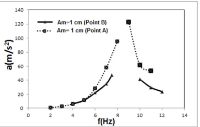
Figure 7 Acceleration vs. imposed frequency for the structure without DVA recorded at second and third floors (points B and A, respectively) using an imposed amplitude of 1 cm.
3.4 Forced vibrations: structure behavior with DVA
To evaluate the effect of the DVA in the vibratory behavior of the structure, a device composed by a steel plate is attached by springs to the original structure. Several testing on the structure with DVA were carried out under the same analysis conditions than those performed in the structure without DVA and detailed in Section 3.3. The imposed frequencies are between the range 1 to 15 Hz, meanwhile only one imposed amplitude was analyzed (Am = 1 cm). In the frequency range mentioned above, two vibration eigenmodes are found for the structure with DVA. Hence, from this configuration and in the range of frequencies analyzed, the active range (i.e. the frequency range where the responses are reduced) can be clearly determined. In this section only results obtained with a DVA of mass m1= 0.78 kg. Nevertheless, the effect of the
DVA mass plate is also evaluated when using a DVA of mass m 2=0.64 kg, DVA mass effects
are only commented in Section 4.
Figure 8 plots the acceleration vs. imposed frequency when the DVA is positioned at point A (top of the structure). As it was mentioned above, the reported acceleration values are obtained after applying FFT to the acceleration vs. time signal recorded by the accelerometer.
0 10 20 30 40 50 60 70
0 2 4 6 8 10 12 14 16
a( m /s
2)
f(Hz) with DVA-m1-Point A
Figure 8 Acceleration vs. imposed frequency for the structure with DVA of mass m1=0.78 kg positioned at
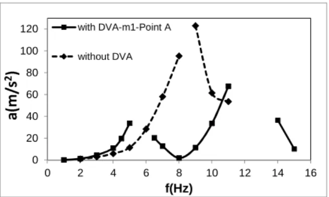
Figure 9 compares the structural dynamic behavior for the structure without and with DVA located in the third floor (top of the structure).
0 20 40 60 80 100 120
0 2 4 6 8 10 12 14 16
a( m /s
2)
f(Hz)
with DVA-m1-Point A
without DVA
Figure 9 Comparative plots for Acceleration vs. imposed frequency for the structure without and with DVA of mass m1= 0.784 kg positioned at the top of the structure (point A).
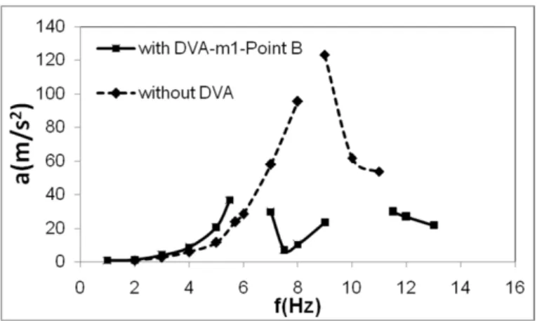
The position where the DVA is located into the original structure is relevant to obtain satisfactory control of vibrations. Figures 10 and 11 show the results when the absorber is positioned in the second level of the structure. The acceleration vs. imposed frequency curves obtained for the structure with DVA is depicted in Figure 10, while a comparison of such results with those registered for the structure without DVA is presented in Figure 11.
0 5 10 15 20 25 30 35 40
0 2 4 6 8 10 12 14
a(
m
/s
2
)
f(Hz)
with DVA-m1-Point B
Figure 10 Acceleration vs. imposed frequency for the structure with DVA of mass m1 = 0.78 kg positioned
at the second floor of the structure (point B).
To evaluate the contribution of the absorber to the vibratory control of the structure, we present in Figure 12 the ratio between the accelerations registered without and with DVA at the same imposed frequency, i.e. R=a with−DV A/a without−DV A, with the vibration absorber positioned at two different levels. Figure 12 clearly shows that the absorber reduces the vibratory amplitude within the active rage. Moreover, such a range enlarges when the absorber is positioned at top of the structure.
Figure 11 Comparative plots for Acceleration vs. imposed frequency for the structure without and with DVA of mass m1 = 0.78 kg positioned at the second floor of the structure (point B).
0 0.5 1 1.5 2 2.5 3
2 4 6 8 10
R
f(Hz)
R(Point A)
R(Point B)
Figure 12 Evaluation of the real contribution of DVA positioned at two different levels on the vibratory control of the structure in the analyzed frequencies range.
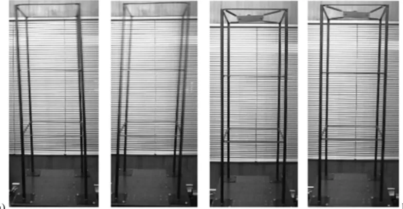
when the DVA is not used and when it is. The frequency of imposed support motion is 8 Hz with amplitude of 1 cm. As it is clearly seen, the high deformation induced near the first resonance mode is reduced when the absorber is used. The motion of the DVA is also apparent from the snap shot.
4 ANALYSIS AND DISCUSSION OF RESULTS
From the experimental results obtained both for free vibration (figure 5) and forced vibration (figures 6 and 7) it is shown that the first mode of vibration of the original structure happens at frequency f=8.48.
a) b)
Figure 13 Frames showing structure responses during forced vibration at frequency 8 Hz and imposed amplitude of 1 cm: a) without and b) with absorber.
value of acceleration vs. imposed frequency (ranged from 1 to 15 Hz) when two different im-posed amplitudes are applied. According to these values, larger structural accelerations are obtained when increasing imposed support amplitudes. Figure 7 presents the experimental results for 1 cm amplitude of the imposed movement, when the DVA is positioned at points A and B of the structure (top and second level of the structure, respectively). That figure shows a similar structural behavior until approximately 5 Hz; from that frequency the spatial config-uration of the first mode of vibration begins to be observed, being the acceleration amplitudes higher at the third floor than at the second.
Incorporating a DVA tuned with the first vibration mode neutralize the structural displace-ments. Figure 8 characterizes the response of the structure subject to a sinusoidal support motion of different imposed frequency (ranged from 1 to 15 Hz) and constant amplitude of 1 cm. The plot proves the theory, showing clearly the two new frequencies and the neutralization of the original frequency. Figure 9 compares the answer of the original system without DVA and with DVA located in the third floor. An excellent tuning is appreciated and a good size active bandwidth has been obtained, as it is expected in the design of this type of devices. The acceleration amplitudes close to the first mode of the original structure (primary resonance) decrease considerably.
Figures 10 and 11 evaluate the answer of the same original system, but with the incor-poration of the DVA in the second floor of the structure. Figure 10 shows that this DVA location fairly suppresses the original vibration first mode, decreasing the active bandwidth size in comparison with that previously analyzed. Figure 11 plots the responses without and with DVA showing the suppression of large accelerations at the first vibration mode of the original structure.
have been found. The other studied case, DVA positioned in the second floor, has presented frequencies of 6.1 Hz and 9.94 Hz. From these experimental measurements, it can be deter-mined that DVA positioned at the top of the structure provides a width range of frequencies where vibration control plays a relevant role, which evidences a better behavior under forced vibration.
Additionally, a study varying the mass’s absorber has been also carried out using m 2 =
0.64 kg for such device, positioned at the top of the structure. From the experiments, the active range is reduced while the responses increase with respect to those obtained for m 1=
0.784 kg.
In order to evaluate the efficiency of the dynamic vibration absorber location, in Figure 12 it is shown the normalized acceleration amplitudes for the cases with DVA located in the third and second floor. Both configurations neutralize the vibratory response generated for frequency f=8.48 Hz. Nevertheless, the active band and the amplitude behavior are different. Specifically, the first configuration (DVA in third floor) presents a wider bandwidth, which is better from the operational point of view. Besides, the development of vibration modes is less pronounced for the first option, being this one the recommended by the authors.
The dimensional analysis requires additional work to confirm when measurements taken from physical models can be extrapolated to a prototype. To this end, numerical simulations could be addressed to analyze correlations between frequencies and structural rigidity. In the present work, a short study was conducted to evaluate the validity of the scales summarized in Table 1. The computed natural frequencies for both model and prototype verify the assumed frequency scale (see Table 3).
5 CONCLUSIONS
AcknowledgmentsThe authors thank CONICYT for supporting the present work in the frame-work of the project FONDECYT 1095028.
References
[1] Multiphysics modeling and simulation software. COMSOL®under License Number: 2075700 - USACH.
[2] N.D. Anh, H. Matsuhisa, L.D. Viet, and M. Yasuda. Vibration control of an inverted pendulum type structure by passive mass-spring-pendulum dynamic vibration absorber. J Sound Vib, 307(1-2):187–201, 2007.
[3] C.F. Beards. Structural Vibration Analysis and Damping. Oxford: Butterworth-Heinemann, 1996.
[4] J.H. Bonsel, R.H.B. Fey, and H. Nijmeijer. Application of a dynamic vibration absorber to a piecewise linear beam system. Nonlinear Dyn, 37:227–243, 2004.
[5] B. Chen and Y.L. Xu. Integrated vibration control and health monitoring of building structures using semi-active friction dampers: Part ii-numerical investigation. Eng Struct, 30(3):573–587, 2008.
[6] M. Chiba and T. Furukawa. A new approach to vibration reduction analysis using thin polymide tape inserted between structural elements. Exp Mech, 2010. DOI: 10.1007/s11340-010-9447-y.
[7] A.K. Chopra.Dynamics of Structures: theory and applications to earthquake engineering. Prentice-Hall, New Jersey, 1995.
[8] S. Ekwaro-Osire, C. Ozerdim, and M.P.H. Khandaker. Effect of attachment configuration on impact vibration absorbers. Exp Mech, 46:669–681, 2006.
[9] F. Fischer. Wind-excited vibrations-solution by passive dynamic vibration absorbers of different types. J Wind Eng And Aerodyn, 95(9-11):1028–1039, 2007.
[10] H. Gao, K.S.C. Kwok, and B. Samali. Characteristics of multiple tuned liquid column dampers in suppressing structural vibration.Eng Struct, 21(4):316–333, 1999.
[11] A. Ghosh and B. Basu. Seismic vibration control of short period structures using the liquid column damper. Eng Struct, 26(13):1905–1913, 2004.
[12] C.M. Harris and A.G. Piersol. Harris’s Shock and Vibration Handbook. McGraw-Hill., New York, 2002.
[13] Y.H. Huang and C.C. Chen. Optimal design of dynamic absorbers on vibration and noise control of the fuselage.
Comput Struct, 76(6):691–702, 2000.
[14] J.C. Ji and N. Zhang. Suppression of the primary resonance vibration of a forced nonlinear system using a dynamic vibration absorber. J Sound Vib, 329:2044–2056, 2010.
[15] B.G. Korenev and L.M. Reznikov. Dynamic vibration absorbers: Theory and technical applications. Wiley & Sons Ltd, 1993.
[16] C.C. Lin, L.Y. Lu, G.L. Lin, and T.W. Yang. Vibration control of seismic structures using semi-active friction multiple tuned mass damper. Eng Struct, 32(10):3404–3417, 2010.
[17] L. Manevitch, A. Musienco, and C.H. Lamarque. New analytical approach to energy pumping oscillators problem in strongly non homogeneous 2dof systems.Meccanica, 42:77–83, 2007. doi:10.1007/s11012-006-9021-y.
[18] J. Park and D.L. Palumbo. Damping of structural vibration using lightweight granular materials. Exp Mech, 49(5):697–705, 2009.
[19] M. Paz. Din´amica estructural: teor´ıa y c´alculo. Barcelona: Revert´e, 3a
ed edition, 1992.
[20] T. Pham, S. Pernot, and C. Lamarque. Competitive energy transfer between a two degree-of-freedom dynamic system and an absorber with essential nonlinearity.Nonlinear Dyn, 62:573–592, 2010.
[21] W. Weaver, S.P. Timoshenko, and D.H. Young. Vibration Problems in Engineering. Wiley-Interscience, 5th edition, 1990.
[22] J.J. Wu. Use equivalent damper method for free vibration analysis of beam carrying multiple two degree-of-freedom spring-damper-mass systems. J Sound Vib, 281(1-2):275–293, 2005.
[23] Y.L. Xu, W.L. Qu, and B. Chen. Active/robust moment controllers for seismic response control of a large span building on top of ship lift tower. J Sound Vib, 261(3-5):277–296, 2003.