Abstract—Bearing Faults in rotating machinery occur as low energy impulses in their vibration signal and are lost in the noise. This signal has to be properly denoised before analyzing for effective condition monitoring. This paper proposes a novel method to denoise and analyze such a noisy signal. The Undecimated Discrete Wavelet Transform (UDWT) with Morlet wavelet based De-noising method is used to denoise the signal. Then this denoised signal is decomposed by Empirical Mode Decomposition (EMD) into a number of Intrinsic Mode Functions (IMF). The impulses in the signal, corresponding to the characteristic fault frequency, are seen clearly in the FFT of the IMFs. A Fast Fourier Transform (FFT), Wavelet Transform (WT), Empirical Mode Decomposition and Envelope Detection are also performed with the acquired signal and all the results are compared with the proposed method. These results clearly show the effectiveness of proposed method in detecting the faults.
Index Terms—Bearing fault, condition monitoring,
undecimated discrete wavelet transform denoising, Morlet wavelet, empirical mode decomposition.
Original Research Paper DOI: 10.7251/ELS1317001R
I. INTRODUCTION
ARLY fault detection in rotating machineries is useful in terms of system maintenance and process automation, which will help to save millions on emergency maintenance and production costs. Faulty bearings contribute to majority of the problems in rotating machinery than any other parts [1]. Quite naturally, fault identification of rolling element bearings has been a subject of extensive research. Bentley [2] had shown that approximately 90% of rolling element-bearing failures are related to either inner race or outer race flaws. These faults are characterized by sharp peaks at periodic intervals but they are of low energy. These signals are modulated by number of high frequency harmonic components resulting from the structural response to individual impacts. Due to this, the characteristic frequency is lost in the noise and an efficient denoising technique is
Manuscript received 8 November 2012. Received in revised form 14 February 2013. Accepted for publication 27 February 2013.
A. S. Raj is with Real Time Systems Division, Instrumentation and Control Group, Indira Gandhi Centre for Atomic Research, Dept. of Atomic Energy, Govt. of India (corresponding author, phone: +91-44-27480500 (extn:22872), e-mail: [email protected]).
N. Murali is Associate Director, Instrumentation and Control Group, Indira Gandhi Centre for Atomic Research, Dept. of Atomic Energy, Govt. of India (e-mail: [email protected]).
required before analyzing the signal for the characteristic fault frequency retrieval [3].
If the noise type and frequency range are known, different filters can be used for denoising [4]. However in vibration analysis, neither the noise type nor the frequency range is known. For such applications, wavelet transform has been widely used, due to its extraordinary time-frequency representation capability [5]. Different thresholding techniques are also proposed in various literatures [5-6].The methods discussed in these literatures are suitable for smooth signals that are to be separated from Gaussian noise. But for fault diagnosis, the vibration signal is characterized with impulses and the noise in the signal is also not Gaussian.
To effectively denoise the vibration signal, Morlet wavelet based denoising method is proposed making use of the resemblance between Morlet wavelet and the impulse generated by faults [7]. Undecimated wavelet transform has an advantage over normal DWT in denoising applications, because the aliasing information tends to be lost while applying threshold. This can be overcome in UDWT based denoising techniques.
After proper denoising, the signal has to be analyzed by an efficient method. The bearing signal is a nonlinear and non-stationary. Fast Fourier transform is not efficient as the signal is amplitude modulated and FFT is meant for linear and stationary signals [8]. Wavelet Transform is designed for linear signals only and they have the leakage problem due to limited length of the window [9]. Another drawback of WT is that it uses decomposition scale for analysis and does not take the signal characteristics into consideration. Empirical Mode Decomposition decomposes the signal based on frequency content and its variation [10]. Peng et.al. [9] compared the analysis of the signal using both WT and EMD. The Fourier transform of the IMFs obtained by decomposing the signal by EMD shows better results when compared to other techniques [10].
Envelope Detection is a benchmark method for bearing diagnostics for over many years now. Envelope analysis is an analogue method for extracting the impulses from a noisy signal. Instead of the obsolete analogue method, considerable advantage can be achieved by utilizing the available digital processing techniques. One such method is the Hilbert transform which can be used for amplitude demodulation as discussed by Randall et.al [11].
A more accurate technique of bearing fault diagnosis is thus
Morlet Wavelet UDWT Denoising and EMD
based Bearing Fault Diagnosis
A. Santhana Raj and N. Murali
proposed in this paper by using efficient technique for both denoising and analysis of signals where other methods fail to detect the faults. UDWT denoising with Morlet wavelet as the base wavelet is performed to remove the noise. Then by EMD method IMFs are generated and their FFT vividly shows the characteristic fault frequencies present. The flow diagram of the proposed hybrid method is given in Fig. 1.
Fig. 1. Block Diagram of proposed hybrid method.
The remaining sections of the paper are organized as follows. The Undecimated discrete wavelet transform algorithm for denoising the signal is explained in the second chapter. The EMD decomposition with FFT analysis is discussed in the third chapter thereby explaining the proposed method of fault analysis. Chapter four discusses the experimental setup and data collected. The other methods for analysis like FFT, Wavelet transform, EMD and Envelope Detection are also done on the signal in chapter five. The proposed method is used to analyze the acquired signal and the results are shown in chapter six. Chapter seven discusses the results obtained with different analysis methods. Conclusion is drawn in chapter VIII.
II. DISCRETE WAVELET BASED DENOISING
Discrete Wavelet based denoising is based on the principle of multi-resolution analysis. Multilevel discrete wavelet decomposition is carried out on the vibration signal to obtain the discrete detail coefficient and approximation coefficients.
While decomposition using an orthogonal wavelet, the energy of the signal is collected in fewer coefficients as the number of decomposition level increases. Energy is preserved because the orthogonal filters are chosen. Consequently these coefficients have become larger. The noise, being random, remains uniformly distributed over all levels. Thus due to the energy preservation, most of the coefficients coming from noise must be small. It is therefore reasonable to do denoising by setting the small coefficients equal to zero [12].
A. Undecimated Discrete Wavelet Transform Based Denoising
While Decomposition of a signal using discrete wavelet transform, the details have some information of aliasing in different levels of decomposition. While thresholding, there is a danger of losing these aliasing information, thereby resulting in improper reconstruction of the signal. In normal wavelet transform, also known as, Decimated wavelet transform, the signal is band filtered and followed by decimation by two in each level. If the down sampling part alone is skipped, then the signal length will not be decreased and at the same time no aliasing information is present. This is a strong advantage while dealing with low signal to noise ratio signals [13].
In addition to the above mentioned property of UDWT, it also exhibits shift invariance [14]. Shift Invariance denotes that the Wavelet Transforms of the signal and its shifted versions are the same, which is not seen in an ordinary DWT. Since decimation is not done, UDWT gives more amount of information compared to DWT. The drawback of UDWT is that it requires bigger computational memory and redundancy in the coefficients.
B. Morlet Wavelet
The wavelet based denoising method is based on orthogonal wavelets. This method assumes the noise to be independent and identically distributed and the signal to be smooth. These are not the case in bearing fault diagnosis. So the use of non-orthogonal wavelets can provide the desired noise removal.
The use of Morlet wavelet, a non-orthogonal wavelet, for bearing fault diagnosis is proved to be efficient than other regular orthogonal wavelets [11]. Morlet wavelet which is a complex wavelet and can be decomposed into real and imaginary parts as,
(
t)
t t r 0 2 2 2 cos 2 exp 2 1 )( β πυ
π ψ ⎟⎟ ⎠ ⎞ ⎜⎜ ⎝ ⎛ −
= (1)
(
t)
t t i 0 2 2 2 sin 2 exp 2 1 )( β πυ
π ψ ⎟⎟ ⎠ ⎞ ⎜⎜ ⎝ ⎛ −
= (2)
where υ0 is a constant, and β is a shape parameter, used for
balancing the time resolution and the frequency resolution of the Morlet wavelet. In general only the real part of the Morlet wavelet is used. From the equation of the Morlet wavelet, one can see that the real part of the wave is nothing but a cosine signal which decays exponentially on both sides of the y axis, which is similar to the impulse generated in faulty bearings. The optimal selection of shape factor β is done by Shannon entropy analysis [7]. The spectra, coherence, cross covariance and time delay functions are smoother and less noisy in high frequency band with the use of Morlet wavelet.
III. EMPIRICAL MODE DECOMPOSITION
The empirical mode decomposition method is necessary to deal with data from non-stationary and nonlinear process. This Receive Vibration Signal
5 level UDWT Decomposition
Neutralise noise & Recompose signal
Generate IMFs
Select IMF of Fault Frequency Range FFT for Peak Detection Morlet
Wavelet UDWT
method decomposes the signal into a number of simple intrinsic mode of oscillations, known as Intrinsic mode functions (IMF).
The IMF has variable amplitude and frequency as functions of time. With this property, the decomposition procedure is defined by Huang vividly with examples [15].
Certain IMFs may have a sudden change in waveform at the extremes of the graph. This is called as End Swing. This may eventually propagate inward and corrupt the whole signal span leading to undesirable IMFs in the EMD process. This end swing affects especially the low frequency components. The cause of this behavior is the inherent problem in the spline fitting. This problem can be avoided by proper selection of IMFs [9].
IV. EXPERIMENTAL SETUP
The vibration data that was used for analysis is obtained from CWRU bearing data center [16]. Reliance Electric’s 2 hp motor along with a torque transducer, dynamometer and control electronics constitute the test setup. The specifications of the 6205-2RS-JEM SKF deep groove ball bearing are given in Table I. With the help of electrostatic discharge machining, faults of sizes 0.007 and 0.021 inches are made. The vibration data is collected using accelerometers placed at 3‘o’clock position. The data was sampled at a frequency of 12 kHz. The rotational frequency (Fr) is 29 Hz.
When a fault occurs in a bearing either at inner race (IR) or
outer race (OR), impulses of vibration are created at specific frequency. These characteristic frequencies for different faults are given by formulas in [17].
TABLEI BEARING DETAILS
Parameters Values (Inches)
Inner Race (IR) Diameter 0.9843 Outer Race (OR) Diameter 2.0472
Thickness 0.5906
Ball Diameter 0.3126
Pitch Diameter 1.5370
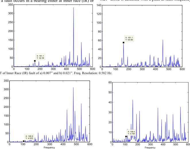
With the required values specific for the bearing is listed in Table I. The characteristic frequency for inner race and outer race faults are 162.19 Hz and 107.36 Hz respectively.
V. BEARING FAULT DIAGNOSIS A. Analysis using FFT and WT
Four sets of data are obtained from bearing data center with different faults, namely Inner Race faults of 0.007 and 0.021 inches thick and outer race faults of 0.007 and 0.021 inches thick.
The Figs. 2 and 3 show the FFT of these acquired data. It is noted that peak is not visible at the characteristic frequency of outer race faulty signal. The signal with inner race fault of size 0.21” alone is detected with a peak at fault frequency.
0 100 200 300 400 500 600
0 50 100 150 200 250 300 350
X: 161.1 Y: 32.39
0 100 200 300 400 500 600
0 20 40 60 80 100 120 140
X: 161.1 Y: 54.99
Fig. 2. FFT of Inner Race (IR) fault of a) 0.007” and b) 0.021”. Freq. Resolution: 0.582 Hz.
0 100 200 300 400 500 600
0 50 100 150 200 250 300 350
X: 106.9 Y: 4.525
Frequency
0 100 200 300 400 500 600
0 10 20 30 40 50 60
X: 108.4 Y: 5.706
Frequency
Wavelet analysis is a good technique for impulse detection in bearing fault as it is applicable for non-stationary signals also. Five-level decomposition with DWT based on Daubechies-4 wavelet is done on the filtered signal. The input signal is divided with respect to frequency bands by this
decomposition and named as Approximation (A) and Detail (D) coefficients. The FFT plots of those Details which constitute our interested area of fault frequencies are plotted in Figs. 4 and 5. It can be seen that the OR fault’s characteristic frequency is not seen clearly.
0 100 200 300 400 500 600
0 50 100 150 200 250
X: 161.1 Y: 31.19
Frequency
0 100 200 300 400 500 600
0 5 10 15 20 25
X: 161.1 Y: 18.45
Frequency
Fig. 4. FFTs of 3rd Detail (D3) of IR fault of a) 0.007” and b) 0.021”. Freq. Resolution: 0.582 Hz.
0 100 200 300 400 500 600
0 5 10 15 20 25
X: 104 Y: 4.447
Frequency
0 100 200 300 400 500 600
0 20 40 60 80 100
X: 102.5 Y: 54.24
Frequency
0 50 100 150 200 250 0
10 20 30 40 50 60
X: 161.1 Y: 50.44
Frequency
0 50 100 150 200 250 300
0 5 10 15 20 25 30
X: 161.1 Y: 18.45
Frequency
Fig. 6. FFT of 3rd IMF of IR fault of a) 0.007” and b) 0.021”. Freq. Resolution: 0.582 Hz.
0 50 100 150 200 250
0 0.5 1 1.5 2 2.5 3 3.5 4 4.5
X: 102.5 Y: 2.237
Frequency
0 50 100 150 200 250
0 2 4 6 8 10 12
X: 106.9 Y: 8.75
Frequency
Fig. 7. FFT of 3rd IMF of OR fault of a) 0.007” and b) 0.021”. Freq. Resolution: 0.582 Hz.
B. Analysis Using EMD
Empirical Mode Decomposition based analysis is performed on the signal next. In EMD, the signal is decomposed into several Intrinsic Mode Functions. The FFTs of these IMFs with the respective characteristic defect frequency peak is shown in Figs. 6 and 7. The fault frequencies record a distinctive high peak in IR faulty signal but not so for OR faulty signal.
C. Envelope Detection
Due to inherent slip in all bearings, there is a fundamental change in the characteristic of the signal. Due to these inherent slips, the diagnostic information is not obtained from other frequency analyses of raw signals and envelope analysis is often able to extract the required impulses. In digital domain, Envelope Detection is done by the using Hilbert transform which has been proved to provide sufficiently better results comparatively.
The Figs. 8 and 9 show the FFT of envelope Detection done on the four faulty signals obtained as mentioned earlier. It can be seen that this traditional method also fails for the OR faulty signal of fault size 0.007”.
VI. ANALYSIS BY UDWT DENOISING USING MORLET
WAVELET AND EMD
From chapter V, it is clear that all the methods, i.e., FFT, WT, EMD and Envelope Detection have failed to detect fault frequencies for OR fault. High noise ridden signal is common in vibration analysis and this paper proposes a novel method for such noisy signal. Because of the high noise, a Morlet wavelet based UDWT denoising followed by EMD decomposition is preferred.
As the OR fault of 0.007” is difficult to identify, this faulty signal alone was taken for analysis using this proposed new hybrid method. While denoising, hard thresholding with a limit of 0.2 units is applied. This denoised signal is then analyzed with EMD. Fig. 10 shows how the UDWT based denoised signal has impulses that are not visible with earlier methods.
0 100 200 300 400 500 600 700 800 0
10 20 30 40 50 60
X: 161.1 Y: 53.51
0 100 200 300 400 500 600 700 800
0 20 40 60 80 100 120
X: 162.6 Y: 85.14
Fig. 8. FFT of envelope analysis of IR fault of a) 0.007” and b) 0.021”. Freq. Resolution: 0.582 Hz.
0 100 200 300 400 500 600 700 80
0 2 4 6 8 10 12 14 16 18
X: 105.5 Y: 8.449
Frequency (Hz)
0 100 200 300 400 500 600 700 800
0 50 100 150 200 250 300
X: 106.9 Y: 114.9
Frequency (Hz)
Fig. 9. FFT of Envelope analysis of OR fault of a) 0.007” and b) 0.021”. Freq. Resolution: 0.582 Hz.
0 50 100 150 200 250
0 0.5 1 1.5 2 2.5 3 3.5 4 4.5x 10
5
Frequency X: 98.14 Y: 3.903e+005
0 50 100 150 200 250
0 0.5 1 1.5 2 2.5x 10
5
X: 108.4 Y: 2.093e+005
Frequency
Fig. 10. FFT of the 2nd IMF obtained from a) DWT based Denoised signal and b) UDWT based Denoised signal (analysis as per the proposed method). Freq.
Resolution: 0.582 Hz.
Fig. 10(b) shows the vibration signal analyzed by the proposed new method of Morlet wavelet UDWT de-noising and EMD based analysis. From the results shown in the figures 2-10, it can be clearly seen that the proposed method alone works excellently and can be used for signals with very low SNR.
VII. DISCUSSIONS
The Fourier Transform based methods assume that the signal can be decomposed into multiple components where only the sinusoidal pattern is permissible for each component.
Therefore, when dealing with vibration signals of bearing faults, whose patterns are similar to impulses and their amplitudes vary with time, Fourier based method does not reveal its periodicity explicitly. This is shown in the above Figs. 2 and 3 that FFT is not able to detect the impulses hidden in noise.
0 50 100 150 200 250 0
0.5 1 1.5 2 2.5 3 3.5x 10
5
X: 161.1 Y: 3.18e+05
Frequency
0 50 100 150 200 250
0 1 2 3 4 5 6 7 8 9x 10
5
X: 161.1 Y: 8.276e+05
Frequency
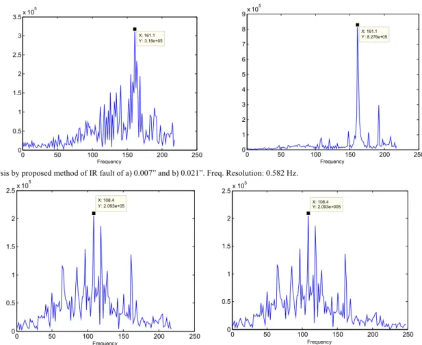
Fig. 11. Analysis by proposed method of IR fault of a) 0.007” and b) 0.021”. Freq. Resolution: 0.582 Hz.
0 50 100 150 200 250
0 0.5 1 1.5 2 2.5x 10
5
X: 108.4 Y: 2.093e+05
Frequency
0 50 100 150 200 250
0 0.5 1 1.5 2 2.5x 10
5
X: 108.4 Y: 2.093e+005
Frequency
Fig. 12. Analysis by proposed method of OR fault of a) 0.007” and b) 0.021”. Freq. Resolution: 0.582 Hz.
The EMD analysis of the vibration signals are shown in Figs. 6 and 7. It is apparent that for IR faults, EMD based analysis methods is able to provide satisfactory results. But for OR faults it does not. Usually detection of IR fault is difficult when compared to OR faults. Here the difficulty in detecting OR faults can be correlated to high noise in the OR faulty signal alone which is due to the noise addition during measurement. The benchmark method for bearing analysis, Envelope method, also have failed to detect the OR faults of both sizes as seen in Figs. 8 and 9.
To prove the importance of UDWT based denoising, FFTs of the 2nd IMF for both DWT and UDWT based denoised signal are shown in Fig. 10. It is evident that DWT based denoised signal has a peak at 98 Hz and not at the expected frequency of 108 Hz.
From the results shown in the Figs. 2-10(a), it is obvious that all the available methods FFT, WT, EMD, Envelope Detection and DWT based denoising fails in detecting the fault and in Fig. 10(b), the proposed method of Morlet wavelet UDWT denoising and EMD based bearing fault diagnosis alone works excellently especially for signals with very low SNR.
Figs. 11 and 12 show the analysis by the proposed method of IR fault signal and OR fault signals respectively. Thus, substantiating that the proposed method works well for all types of faults.
VIII. CONCLUSION
The earlier methods of bearing fault diagnosis like FFT, Wavelet Transform, EMD and Envelope Detection method are shown that they are ineffective with the noisy data selected for analysis. The best denoising method, the Morlet wavelet based UDWT denoising technique, is selected for efficient denoising. Using the Undecimated Discrete Wavelet Transform based denoising, the reconstruction is better and prevents loss of valuable aliasing data. Instead of using any orthogonal wavelets for wavelet decomposition while denoising, Morlet wavelet is used for its close resemblance with the impulse. Empirical mode Decomposition method is done to analyze the denoised signal in this paper. The peaks corresponding to the characteristic frequencies of the fault can be seen clearly with the proposed novel method, which were hidden in the noise in the earlier methods.
ACKNOWLEDGEMENT
The authors would like to thank Case Western Reserve University for providing free access to the bearing vibration experimental data from their website [16].
REFERENCES
[2] D.Bently, “Predictive maintenance through the monitoring and diagnostics of rolling element bearings”, Bently Nevada Co., Application Note 44, pp 2-8, 1989.
[3] A.S.Raj, N.Murali,”Early Classification of Bearing Faults using Morphological operators and Fuzzy Inference”, IEEE Trans. Industrial Electronics, vol.60, no.2, pp.567-574,2013
[4] S.Sophocles, J.Orfanidis, “Introduction to signal processing”, Prentice hall, 1996.
[5] Donoho,D.L., “Denoising and Soft thresholding”, IEEE Trans. Inf. Theory, vol.41, no.3,1995.
[6] Pan.Q., Zhang.L.,Dai.G., Zhang.H., “Two denoising methods by wavelet transform”, IEEE Trans. Signal processing, 47(12), 1999.
[7] Lin.J., and Qu.L., “Feature Extraction based on Morlet wavelet and its application for mechanical fault diagnosis”, J. Sound and Vibration, vol.234, no.1, 2000.
[8] Rai.V.K.,Mohanty.A.R., “Condition Monitoring techniques for rolling element bearing: an overview ”, Proc. Role of NDE in Modern mainTenance Management, IACR, 2005.
[9] Peng.Z.K.,Tse.P.W., Chu.F.L., “A comparison study of improved Hilbert-Huang transform and Wavelet Transform: application to fault diagnosis for roller bearing”, Mechanical Systems and Signal Processing, vol.19, 2005.
[10] Rai.V.K.,Mohanty.A.R., “Bearing Fault Diagnosis using FFT of intrinsic mode functions in Hilbert-huang Transform”, Mechanical Systems and Signal Processing, vol.21, 2007.
[11] R.B. Randall, J. Antoni, S. Chobsaard, “The relationship between spectral correlation and envelope analysis in the diagnostics of bearing faults and other cyclostationary machine signals”, Mechanical Systems and Signal Processing,vol.15, no.5, pp.945–962, 2001.
[12] Lin.J.,Zuo.M.J., Fyfe.K.R., “Mechanical Fault detection based on the wavelet Denoising technique”, J. Vibration and Acoustics, vol.126, no.9, 2004.
[13] Fugal.D.L., “Conceptual wavelets in Digital Signal Processing”, Space and Signals technical publishing, CA, 2009.
[14] Undecimated wavelet transform for Image Denoising, UNR Computer Vision Laboratory,
[15] http://www.cse.unr.edu/CRCD/Summer02/aglika1/index.html.
[16] Huang.N.E.,Shen.Z., Long.S.R., “The empirical mode decomposition and the Hilbert transform for nonlinear and non-stationary time series analysis”, Proc. Royal Society of London Series A, 454, 1998.
[17] Bearing Data center, http://www.eecs.case.edu/laboratory/bearing, Case Western Reserve University.