*e-mail: [email protected]
Current Transformers with Nanocrystalline Alloy Toroidal Core:
Analytical, Computational and Experimental Studies
Benedito Antonio Lucianoa, Thiago de Carvalho Batistab*, Raimundo Carlos Silvério Freirea,
Francisco das Chagas Fernandes Guerraa, Walman Benício de Castroc
aDepartamento de Engenharia Elétrica, Universidade Federal de Campina Grande – UFCG,
Rua Aprígio Veloso, 882, CEP 58429-900, Campina Grande, PB, Brasil
bPrograma de Pós-graduação em Engenharia Elétrica, Universidade Federal de Campina Grande – UFCG,
Rua Aprígio Veloso, 882, CEP 58429-900, Campina Grande, PB, Brasil
cDepartamento de Engenharia Mecânica, Universidade Federal de Campina Grande – UFCG,
Rua Aprígio Veloso, 882, CEP 58429-900, Campina Grande, PB, Brasil
Received: December 2, 2011; Revised: March 1, 2012
In this paper are presented theoretical analysis and experimental results concerning the performance of toroidal cores used in current transformers. For most problems concerning transformers design, analytical methods are useful, but numerical methods provide a better understanding of the transformers electromagnetic behaviour. Numerical field solutions may be used to determine the electrical equivalent circuit parameters of toroidal core current transformers. Since the exciting current of current transformers alters the ratio and phase angle of primary and secondary currents, it is made as small as possible though the use of high permeability and low loss magnetic material in the construction of the core. According to experimental results presented in this work, in comparison with others soft magnetic materials, nanocrystalline alloys appear as the best material to be used in toroidal core for current transformers.
Keywords: current transformers, nanocrystalline alloys, toroidal core
1. Introduction
Chronologically, the development of nanocrystalline alloys potentially applicable in electromagnetic devices began in 1988, after Yoshizawa et al. reported new Fe-based magnetic alloys composed of ultrafine grain structure1. In 1996, Draxler and Styblíková compared the use of nanocrystalline, amorphous and permalloy materials for current transformer construction2. The interest of nanocrystalline application in current transformer cores is based on high performance of these soft magnetic materials such as: high permeability, low coercive force, and low losses. A high permeability level requires easy rotation of magnetic moments, as well as easy domain wall motion, resulting in the demand for low crystalline anisotropy and low magnetostriction. The coercive force is the value of the magnetic field required to move the magnetic domain walls. In microcrystalline materials, the larger diameter of the grains implies increasing difficulty in the movement of the grains. However, in nanocrystalline materials this behaviour is inverse: once the grain size is smaller than the wall thickness, the grain boundaries are not barriers to the movement of the walls, resulting in low value of coercive force. The low losses exhibited by nanocrystalline soft magnetic materials are due to domain refinement and as well as to higher electrical resistivity, usually higher than conventional Si-steel. In comparison to ideal soft magnetic
material, the best nanocrystalline alloys are those who have very narrow hysteresis loop, indicating a very small hysteresis loss, high saturated magnetic flux induction, low coercivity and low core losses3.
This paper firstly summarises analytical and computational studies about current transformers (CT) with toroidal core4. This is followed by a description of experimental measurements and applications of two ferromagnetic materials in the toroidal CT: alloy nanocrystalline Fe73.5Cu1Nb3Si13.5B9 and alloy Fe-3.2% Si grain oriented. These studies aim to examine the influence of magnetic core material on the CT accuracy class, particularly in relation to the angle phase error.
2. Analytical Background
Direct measurement of electrical current flowing in electrical power systems is not straightforward, especially when the current level and the voltage at the media are high. In these cases CT are employed to delivery a galvanically separated image of the primary current.
Current Transformer is an instrument transformer specially designed and assembled to be used in measurement, control, and protective power systems. Its primary winding consists of a few turns, sometimes even a single bar, and is connected in series with the circuit whose electrical
OI:
D 10.1590/S1516-14392012005000051
Luciano et al
current is desired to be measured. The secondary winding is connected to the current-measuring instruments. Typically, CT consists of a specially constructed toroidal core upon which the secondary winding is wrapped and through which the primary winding is passed.
The physical principle of CT operation is based on two fundamental physical laws: the law of Faraday and Ampere’s law. Based on these laws and the theory of magnetically coupled circuits, the CT can be represented by an equivalent electric circuit, referred to the primary winding, as shown in Figure 1[5].
Current Transformers are characterized by some ratios. The first is the marked (nominal) ratio of the primary current to the rated secondary current (Kc = Ipn/Isn). This ratio is a fixed value for a given CT. The second is the true ratio of the rms primary current to the rms secondary current (Kr = Ip/Is) under specified conditions. The true ratio of a CT is not a single fixed value, since it depends on the specified conditions of use, such as secondary burden (Zc), primary current (Ip), frequency (f), and wave form. The third is the ratio correction factor (RCF). It is the factor by which the rated ratio must be multiplied to obtain the true ratio (RCF = Kr/Kc).
Under ideal conditions, the actual current ratio is equal to the nominal ratio and there is no phase angle displacement between the primary and the secondary current. Thus, the designer objective is to alter material properties of real/practical CT to reach improved performance, but CT errors exist mainly due to the exciting current Ie at the magnetizing impedance Zm.
In CT equivalent electric circuit shown in Figure 1 Zs represents the algebraic summation/combination of two leakage impedances: the primary impedance and reflected secondary leakage impedance. In this equivalent circuit, Zs is magnetically linear and Zm is non-linear due to the magnetic nonlinearity of the cored inductance.
The ratio error εc is defined as the percent relative difference between the measured value of the primary current and its exact value, as expressed by:
2 1
1
100%
× −
ε =c r ×
K I I
I
(1)
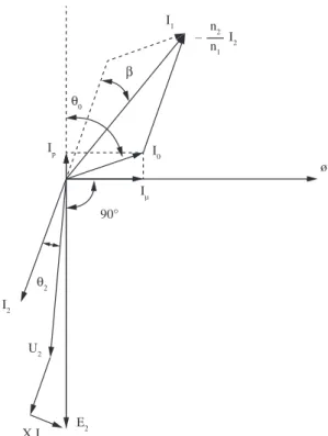
On the other hand, the phase angle error is defined as the angle β presented on the phasor diagram of the CT shown in Figure 2.
In this Figure 2, Φ is the magnetizing flux, and I0 is the exciting current, in concept, separated into two components:
Iµ, the magnetizing current, and Ip, the active losses current. In the secondary circuit: E2 is the induced electromotive force, r2 is the winding resistance, x2 is the leakage reactance,
U2is the terminal voltage, I2 is the secondary current, and
θ2 is the angle between U2 and I2. In addition, it can be seen that the primary current I1 is obtained by phasor sum of I0
and (–n2/n1) I2, where n2 and n1 are the number of turns of the secondary and primary windings.
The main cause of the ratio and phase angle errors of a current transformer is the exciting current Io. In an ideal TC, in which exciting current does not exist, I1 and – (n2/n1)
I2 presented in Figure 2, are coincident. Thus, the primary current value, obtained from the secondary current, would be equal to the absolute value of the vector I1 from the
phasor diagram, and this vector would be delayed from I2
of exactly 180°.
The influence of the exciting and the primary currents on the errors of a CT can be verified observing Figure 2. In this figure, projecting the vectors Io and I2 over the vector I1, gives:
[
]
1= c× 2×cosβ + 0×cos 90º (− α + β + δ)
I K I I
(2)
where α is the angle between the exciting current Io
and the magnetizing flux φ, and δ is the angle between the inverse of I2and the inverse of E2.
Due to its relatively small value, the angle β can be neglected, simplifying the previous expression to:
2 1 0
1 1
( )
× −
= − × α + δ
c
K I I I
sen
I I
(3)
Figure 1. Equivalent electric circuit of a current transformer, referred to the primary winding.
Figure 2. Phasor diagram of a current transformer.
Current Transformers with Nanocrystalline Alloy Toroidal Core: Analytical, Computational and Experimental Studies.
Analyzing the second term of Equation 3, it can be seen that its first member is equal to the ratio error of the CT, which will be considered in its absolute value in a new expression, as:
0
1
( )
ε =c I ×sen +
I α δ (4)
Again, from the phasor diagram of Figure 2, the following expression for the tangent of the angle β can be obtained:
[
]
0
2
90º ( )
cos
× − + +
=
× ×
c
I sen
tg
K I
α β δ
β
β (5)
Considering that the angle β has a relatively small value, a simpler expression can be, then, obtained:
0
1
cos( )
= I × +
I
β α β (6)
As verified in (4) and (6), both the ratio and phase angle errors of the CT increase as the exciting current increases or as the primary current decreases. Then, it is important that the magnetic material of the CT core could demand a small exciting current. Also, the CT could be projected to operate with a primary current value as near as possible of its nominal value, in order to minimize the effects of the primary current in its errors.
In turn, the secondary current of a CT is extremely dependent on its primary current, and it is not influenced by the impedance of the element connected to the secondary terminals of the CT. However, if this impedance exceeds some limit values, determined by the maximum power with which the accuracy class of the CT was obtained, the errors can be much greater than those obtained with the tests.
When an impedance Z is connected to the secondary of a CT, a current I2 flows through it and the ratio and phase angle errors εc and β, respectively, can be determined by (4) and (6). When the absolute value of Z increases, keeping its phase unchanged, it is necessary an increase of the secondary voltage U2 so that the secondary current I2 could stay constant. To achieve this, the electromotive force E2 has to increase its absolute value and also the flux Φ inside the core. As this flux is produced by the exciting current Io, it must also increase its absolute value, increasing the ratio and phase angle errors. This analysis of the influence of the secondary current on the CT errors is important, because it determines the resistance limit of the conductors that could be used to connect the secondary windings of the CT to the equipments that they will supply.
In CT for measurement applications, it is very important to know “ratio” and “phase angle” between the current phasors, because errors in CT can lead to energy measurement errors.
3. Computational Approach Incorporating
the Finite Element Method
Numerical field solutions may be used to determine the electrical equivalent circuit parameters of toroidal core current transformers. The lumped elements of
equivalent circuits correspond very closely to the various physical phenomena in the transformer. Calculation of the magnetizing inductance and minimization of the transformer magnetizing current render considerable interest for designers attempting to reduce the errors in the ratio of turns and phase angle of transformers feeding current-measuring instruments.
When analyzing core materials, FEA can be really useful. The most important point of the FEA analysis is to obtain the distorted wave of the excitation current. This is actually the test problem chosen by Silvester and Chari6 in the revolutionary paper that opened a new era in the electromagnetic computational analysis.
Finite element analysis (FEA) is a powerful method to design and study electric low and high frequency devices. FEA is a numerical method that models a region by dividing it into discrete elements composed of interconnecting nodes. Finite element analysis obtains solution to the model by determining the behavior of each element separately, then combining the individual effects to predict the behavior of entire model.
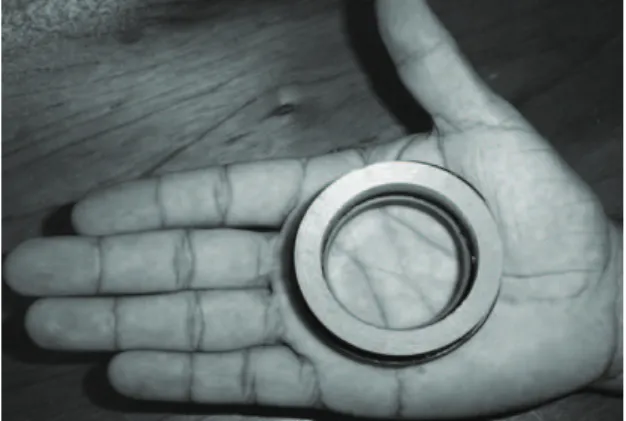
As nanocrystalline alloys are produced in ribbons shapes, it is available toroidal cores with square or rectangular cross-section, as shown in Figure 3.
To modeling model the cross-section of the toroidal core shown in Figure 3, it was used the software package FEMM7. The program FEMM was used to simulate the behavior of a current transformer whose electrical and magnetic circuits were previously developed by analytical procedures or methods. A 2-D model estimates the missing third dimension using either axisymmetric or planar geometry.
4. Experimental Tests
Figure 4 shows the experimental system used to investigate the behavior of the CT with different magnetic materials used in the core. Experimental tests were performed at the Laboratory of Industrial Electronics and Drive Machines, Federal University of Campina Grande, Brazil.
Once the CT has been projected for a power of 5 VA, the NBR 6821[8] standardizes the impedance Z as: resistance
Figure 3. Toroidal core assembled with nanocrystalline alloy with rectangular cross-section.
Luciano et al
5. Results
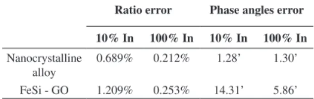
The comparative tests allowed the determination of the ratio errors and phase angles of the CT’s. Results are summarized in Table 1.
As presented in Table 1, the angle errors relation and phase angle are smaller for the nanocrystalline alloy CT core, this difference is more evident for the tests to 10% of rated current (In), and this difference is explained by the greater magnetic permeability of nanocrystalline alloys, that reduces the magnetizing current. Thus, the phase angle error, β, is reduced.
It is worth noting that the CT windings were handmade. The coils are not regularly spaced around the core and the presence of flux leakage will contribute to the increase of the CT error ratio. To reduce this effect, the core windings must be made by specialized machines, like those used in instrument transformers manufactory.
6. Conclusion
From experimental results, it can be observed that the CT with nanocrystalline alloy toroidal core presents lower values of phase angle (phase error) when compared with CT with the toroidal core of FeSi, used with the same rated characteristics, which confirms the expected behavior/ assumptions.
The reason for the better performance of CT based on nanocrystalline toroidal core alloy in terms of phase angle, is due to the magnetic permeability of nanocrystalline alloy Fe73.5Cu1Nb3Si13.5B9 that is higher than the permeability of the magnetic alloy Fe-3.2% Si GO, resulting in lower values of the magnetizing current components and the core losses.
Acknowledgments
The authors wish to express their thanks to NAMITEC, CNPq (Brazil) and CAPES (Brazil) for financial support provided to this work. They are also thankful to Professor Antônio Flavio Licarião Nogueira (UDESC – Brazil) for the comments on the manuscript.
of 0.18 Ω and inductance of 0.232 mH, 60 Hz. These specifications have been approximated by the following arrangements: the parallel association of two 0.5 mH inductors, resulting in a total inductance of 0.25 mH and nine resistors of 1.5 Ω connected in parallel, resulting in a total resistance of 0.195 Ω.
Defining the nominal current for the tests as 5 A, the tests were performed on the rated current between 10 and 100%. The tests were performed applying a purely 60 Hz sinusoidal signal. The first sample consist of a nanocrystalline alloy (Fe73.5Cu1Nb3Si13.5B9 ) core and the second sample consist of a Fe-3.2% Si grain oriented core9.
Figure 4. Schematic diagram of the experimental tests.
Table 1. Comparative ratio errors and phase angles of the current transformers under study.
Ratio error Phase angles error
10% In 100% In 10% In 100% In
Nanocrystalline alloy
0.689% 0.212% 1.28’ 1.30’
FeSi - GO 1.209% 0.253% 14.31’ 5.86’
References
1. Yoshizawa Y, Oguma S and Yamauchi K. New Fe-based soft magnetic alloys composed of ultrafine grain structure. Journal of Applied Physics. 1988; 64(1):6044-6046. http://dx.doi. org/10.1063/1.342149
2. Draxler K and Styblíková R. Use of nanocrystalline materials for current transformer construction. Journal of Magnetism and Magnetic Materials. 1996;157-158:447-448. http://dx.doi. org/10.1016/0304-8853(95)01055-6
3. Ohta M and Yoshizawa Y. Recent progress in high Bs Fe-based nanocrystalline soft magnetic alloys. Journal of Physics D: Applied Physics. 2011; 44:1-6. http://dx.doi.org/10.1088/00 22-3727/44/6/064004
4. Luciano BA, Albuquerque JMC, Castro WB and Afonso CRM. Nanocrystalline material in toroidal cores for current transformer: analytical study and computational simulations.
Materials Research. 2005; 8(4):395-400. http://dx.doi. org/10.1590/S1516-14392005000400007
5. Batista TC, Luciano BA, Freire RCS and Catunda SYC. Current transformer with nanocrystalline alloy core for measurement. In: Proceedings of the IEEE Instrumentation and Measurement Technology Conference I2MTC; 2011; Binjiang, China. Binjiang; 2011. p. 1653-1656.
6. Silvester P and Chari MVK. Finite element solution of saturable magnetic field problems. IEEE Transactions on Power Apparatus and Systems. 1970; 7:1642-1651. http:// dx.doi.org/10.1109/TPAS.1970.292812
7. D. Meeker. Finite element method magnetics. 2010. User’s Manual. Available from: <http://femm.foster-miller.net/wiki/ HomePage>. Access in: 20/09/2010.
8. Associação Brasileira de Normas Técnicas – ABNT. NBR 6821: Transformadores de Corrente - Método de Ensaio. ABNT; 1992. 9. Luciano BA, Freire RCS, Lira JGA, Fontgalland G and
Castro WB. Transformador de Corrente com Núcleo Toroidal de Liga Nanocristalina. IEEE Latin American Transactions. 2006; 4(3):160-164. http://dx.doi.org/10.1109/ TLA.2006.4472108