The Sinusoid as the Longitudinal Profile in Backward-Wave
Oscillators of Large Cross Sectional Area
Joaquim P. Leite Neto and Joaquim J. Barroso
Laborat´orio Associado de Plasma Instituto Nacional de Pesquisas EspaciaisAv. dos Astronautas, 1758 S. Jos´e dos Campos, SP, Brazil
Received on 11 December, 2003
High-power generation in backward-wave oscillators (BWO) of large section requires that the beam electrons flowing close to the corrugated wall interact efficiently with surface waves supported by a periodic structure. Such waves are described by the superposition of slow-wave space harmonics of the operating mode. The present paper reports on design tools for BWOs operating in symmetric TM modes since these modes are able to perturb the axial velocity and electron density on rectilinear beams confined by an external magnetic field in slow-wave systems. Here we investigate whether a cylindrical guide with sinusoidally rippled wall can provide strong coupling between the guide surface waves and mildly relativistic(∼500keV) electron beams
in the 8-9 GHz frequency range for BWOs of large diameter (D ∼3λ). For this purpose, the characteristic equation of a sinusoidally corrugated structure is derived on the basis of the Rayleigh-Fourier method, whereby the field solution is represented by a single expansion of TM eigenmodes. From the dispersion diagrams thus obtained we infer the appropriate periodic length and ripple amplitude of the guiding structure that optimize the beam-wave interaction.
1
Introduction
The backward-wave oscillator (BWO) is a source of electro-magnetic radiation in the centimeter and millimeter wave-length bands, with its capability as a high-power microwave source being demonstrated by the generation of 15 GW out-put power at 3-cm and 3 GW at 8-mm wavelengths [1]. In the simple classical description, the BWO consists of a spatially periodic waveguide into which a high-current elec-tron beam (confined by a selec-trong magnetic field) is injected to drive and interact with azimuthally symmetric transverse magnetic (TM) modes, as just these modes are able to per-turb the axial velocity and electron density on rectilinear be-ams. In many works [2-8] the periodic structure, in general a sinusoidally rippled cylindrical guide, is merely displayed in its final configuration, with no account as to how the ge-ometry of the structure has been synthesized aiming at its particular application. Adressing this basic question, here we present design tools for the synthesis of sinusoidal profi-les from the technical goals for the BWO, namely, the opera-ting frequency and the beam energy. The analysis develops on the basis of the Rayleigh-Fourier method, whereby the field solution is represented by a single expansion of TM space harmonics [10]. This method has been verified by some authors [11-14] as the one (among the least-squares and the integral methods) giving by far the best overall des-cription of wave scattering from sinusoidal surfaces.
Consistent with the design requirements of enough slowing of the TM wave and strong coupling impedance, a sinusoidal profile is specifically synthesized for a 8.9 GHz
BWO driven by a 500 keV electron beam. The RF method is also successfully applied in the analysis of a piecewise continuous profile [7] (with semicircles separated by rec-tangular grooves), which shows to yield a higher coupling impedance upon comparison with the sinusoidal profile.
2
Dispersion relation of the
cylin-drical waveguide with sinusoidally
Rippled Wall
The corrugated structure that we consider consists of a cy-lindrical waveguide with perfectly conducting wall of radius Rw(z)sinusoidally rippled about the mean radiusR0as that commonly employed in high-power BWO experiments [8], [9], i.e.,
Rw(z) =R0(1 +ǫ cos( 2π
d z)) (1)
withǫandddefining the amplitude and the period of cor-rugation, repectively. Due to the spatial periodicity of the structure along the axial coordinate z, azimuthally symme-tric TM elecsymme-tric fields in the cylindrical corrugated system (r, ϕ, z) can be expanded in spatially harmonic series accor-ding to Floquet,s theorem as
Ez(r, z, t) = n=+∞
X
n=−∞
Er(r, z, t) =−i n=+∞
X
n=−∞
An
kzn
k⊥n
J1(k⊥nr) exp(i kznz−iωt)
(3) where
kzn=kz0+ 2π
d n,0≤kz0≤ 2π
d (4)
denotes the longitudinal wavenumber of the nth space har-monic, which is related to the angular frequencyω and to the transverse wavenumberk⊥nthrough
k2
⊥n=
ω2 c2 −k
2
zn (5)
Assumingkz0as the reference propagation constant, the electric field phase shifts by exp (ikznd) in moving fromz
toz+d(at fixed rand ϕ), with the determination ofkz0
(and, hence,kzn) as function ofωbeing the central problem
of a slow-wave structure.
The dispersion equation determining the dependence of the reference wavenumberkz0on the angular frequency fol-lows from the boundary condition requiring that the compo-nent of the electric field tangential to the corrugated surface must vanish, i.e.,
·
Ez(r, z) +Er(r, z)
dRw(z)
dz
¸
r=Rw
= 0 (6)
Substituting (2)-(3) in (6) and expanding the resulting ex-pression in a Fourier integral over [0, 2π], we find an infinite system of algebraic equations for the amplitude coefficients An
n=∞ X
n=−∞
AnCn m(ω, kz0,ǫ , R0, d) = 0 (7)
where ⌋
Cn m=
·
1 + 2π
d (n−m)
¸ k zn k2 ⊥n Z d 0
dz J0(k⊥nRw(z))Cos
µ
(n−m)2π d z
(8)
⌈
The existence of a nontrivial solution to the amplitudes of the space harmonics demands that the determinant of the homogeneous equations (7) be zero. Thus, setting
det|| Cn m||= 0 (9)
yields the eingenvalue for at given corrugated parametersǫ, R0 andd. Normalizing the dispersion relation and solving forω R0/cas function of kz0d/πthe periodic structure is described by two dimensionless parameters,ǫandd/R0.
Although (9) involves an infinite matrix, in practice we truncate the system to an adequate finite rank to obtain an approximation of the exact eigenvalue equation. We have verified that a 9 x 9 matrix gives (for the same structure) eigenvalues differing by 0.1% from those calculated with a higher order matrix. Therefore, in the ensuing calculations the rank of the matrix in (9) (withn=m) is truncated at 9 (−4≤n≤4).
3
Fundamentals of the
backward-wave oscillator
Linear beam relativistic microwave devices are based on the interaction of an electron beam and an electromagnetic fi-eld containing slow-wave components. Such a fifi-eld can be realized in spatially periodic structures. Chiefly among these devices, is the backward-wave oscillator (BWO) with its essential characteristic of allowing electrical tuning, as the operating frequency is approximately determined by the synchronism condition: phase velocity of the wavevph =
electron velocityvz. A BWO schematic is shown in Fig. 1
with the corresponding dispersion diagram, i.e., the depen-dence of the wave frequency on kzd, the phase shift per
period in a slow-wave structure of periodic length d that supports a travelling wave of propagation constantkz.The
dashed line is the light line ω = kzc , which defines the
boundary between regions of fast (vph = ω/kz > c) and
slow (vph < c) waves. A passband refers to a frequency
band ranging from the lower frequency (the cutoff frequency at pointskz = 0,2π/d, ...) and the upper frequency (at the
πpointkz = π/d,3π/d, ...). As we shall see, in a
sinu-soidally rippled structure the passband narrows as the ripple amplitudeǫincreases. The operating point is determined by the intersection of the dispersion curve with the beam line ω = kzvz, corresponding to the condition of Cherenkov
synchronism vph = vz. With the presence of the driving
electron beam, the BWO interaction takes place with the slow space-charge wave,ω = kzvz−ωp (where ωp
iden-tifies the beam plasma frequency), a negative-energy wave whose growth decreases the kinetic energy of the beam. In the dispersion curve of the slow-wave structure, the BWO operates in regions where the group velocityvg =dω/dkz
is negative (π/d < kz <2π/d,etc) and amplify backward
Figure 1. BWO schematics and dispersion diagram showing the first band.
4
Synthesis and analysis of a
sinusoi-dal profile
The results which follow are primarily concerned with si-nusoidal corrugations of small amplitude ǫR0 < λ/4 in oversized cylindrical waveguides of average radiusR0 lar-ger than the free-space wavelength λof the radiation. To assure single-mode operation in such oversized guides we keep the operating point close to the upper edge of the pass-band, theπpoint. In this region, the smallness of the group velocity can make the diffractionQfactor (of the mode of interest)Q=ωd/vglarge enough to favour excitation of the
nominal mode against higher-order competing modes [7]. Then the practical problem we shall discuss relates to the synthesis of a sinusoidally rippled profile for a BWO de-signed to operate in the TM01mode over the 8-9 GHz fre-quency range and to be driven by an electron beam at the injection energy of Wb = 500keV.Eigenfrequencies and
phase velocities for TM01 mode operating close to the π-point are shown as function of the normalized ripple ampli-tudeǫin Figs. 2 and 3, where the normalized periodic length d/R0is taken as parameter. In the plots, the beam energy is set at Wb = (γ−1) mc2 = 500 keV,withγ = 1.978
which gives an electron velocity of 0.86c, wherec is the vacuum light speed. The requirement that the phase velo-city of synchronous space harmonic should be slightly less than0.86cplaces a constraint on the corrugation period, na-mely d/R0 |max≤ 0.35. Then taking d/R0 = 0.35, for instance, and0.03 ≤ ǫ ≤ 0.07the associated frequencies lie within the specified 8-9 GHz frequency range (Fig. 2), yet from Fig. 3 the phase velocity remains above 0.85c and, therefore, adequate slowing of the wave for interacting with the beam is barely achieved. On the other hand, fixing d/R0 = 0.30poses two constraints onǫ, the first of which
requires0.065 ≤ ǫ ≤ 0.085 so as to keep the design fre-quency in the 8-9 GHz range, whereas the second constraint demandsvph≤0.86cto satisfy the synchronism condition.
So we select from Fig. 3ǫ = 0.07atd/R0 = 0.30to ob-tainvph = 0.82cand the operating frequency of 8.6 GHz
(Fig. 2).
Figure 2. TM01-mode upper cutoff frequencies (π−point) as
func-tion of the ripple amplitudeǫwith the normalized period d/R0 as
parameter.
Figure 3. TM01-mode phase velocity (at theπ−point) as function
of the ripple amplitudeǫ.
virtually coincident up tokzod/π ≃ 0.8, with theπ-point
frequencies differing by 2% at the upper edge of the pass-band intercepted by the Doppler beam line (vz = 0.86c) .
But from the point of view of coupling impedance (defined asE2/2k2
z0PwhereEis the average RF electric field at the beam position, and P the power flow on the structure), it becomes apparent from Fig. 6, which shows at z = 0the radial dependence of the electric field, that the field strength near to the corrugated wall is substantially higher in the pie-cewise profile than in the sinusoidal counterpart.
Figure 4. Sinusoidal (R0 = 4.5 cm,ǫ = 1/15, Rmin = 4.2
cm,Rmax = 4.8cm) and piecewise (semicircle radius 0.5 cm and
rectangle height 0.1 cm) profiles with periodic lengthd= 1.4cm.
Figure 5. TM01-mode dispersion diagram corresponding to the
si-nusoidal and piecewise profiles in Fig. 4. Dashed and dotted lines are the light line and the 500 keV-beam Doppler line (vz= 0.86c).
Figure 6. Radial dependence of the TM01-mode electric field on
section z=0.0 of sinusoidal and piecewise profiles shown in Fig. 4.
Figure 7. TM01-mode dispersion diagram for an oversized guide
with longitudinal profile sinusoidally corrugated. The four curves are associated with distinct values of average radiusR0and ripple
amplitudeǫ,but keeping in all casesRmin= 4.2 cm andd= 1.4
cm. Dashed line is the light line.
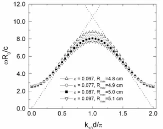
Nevertheless, the field strength and the breadth of the passband (for the sinusoid) can be adjusted by proper va-riation of the corrugation parameters ǫandR0. To clarify this point, we show in Fig. 7 dispersion curves related to four sinusoidal profiles characterized by 1)R0 = 4.50cm, ǫ = 0.0667; 2)R0 = 4.55cm,ǫ = 0.0769; 3)R0 = 4.60 cm,ǫ = 0.0869;4)R0 = 4.65cm,ǫ = 0.0968.Given by R0, the lower cutoff frequency atkzod= 0is the same for
all the curves, while the upper critical frequency, determined byǫ, assumes distinct values on each curve. We see that a dispersion curve flattens asǫincreases, and sodω/dkz
the critical frequency of 8.9 GHz corresponding to the phase velocity of0.82cfor the synchronous space harmonic.
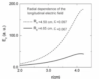
Figure 8. Radial dependence of the TM01-mode electric field (on
section z=0.0) in sinusoidally rippled waveguides.
To address the issue of mode competition concerning the symmetric modes TM01, TM02,and TM03,Fig. 9 plots (to-gether with the 500-keV beam line) their respective disper-sion curves associated with the synthesized sinusoidal pro-file. We see that the beam line crosses the dispersion cur-ves of the higher-order modes (TM02, TM03)at frequen-cies above 10GHz, significantly higher than the 8.9-GHz frequency of the nominal TM01 mode. Well isolated and having the largestQfactor, this makes the TM01mode to be excited more readily than its nearest competitors.
Figure 9. Calculated dispersion diagrams for low-order TM01
modes in the sinusoidally corrugated waveguide (R0 = 4.5cm,
ǫ= 1/15, d= 1.4cm) shown in Fig. 4. Light and beam lines are indicated by dotted and dashed lines.
Finally, to ascertain the validity of the numerical results obtained here from the Rayleigh-Fourier (RF) method, we compare in the Tab. 1, critical frequencies calculated from the RF method and those provided by a simulation puter code [7] used to optimize the piecewise profile com-bined with semicircles and rectangles. So we see that the
Rayleigh-Fourier results fit the WaveSym calculation wihin an accuracy better than 1%.
TABLE 1. Critical frequencies (in GHz) calculated from the Wa-veSym code and from the RF method
h/cm WaveSym Code Rayleigh-Fourier Method 0.1 8.82 8.82
0.2 8.30 8.28
0.3 7.82 7.89
0.4 7.33 7.40
5
Conclusions
A systematic procedure has been given to synthesize, con-sistently with the required operating frequency and injec-tion beam energy, an overmoded sinusoidally corrugated waveguide with application as a slow-wave structure on backward-wave oscillators. The corrugation parameters are selected so that the waveguide when driven by a 500- keV electron beam operates close to the upper cutoff frequency on the first space harmonic of the lower order TM01mode. Consistent with single-mode operation, the periodic struc-ture here designed supports a surface wave that is synch-ronous with a 500-keV electron beam and simultaneously exhibits a large coupling impedance, which is a measure of the RF field strength at the beam position. The surface wave is crucial to avoiding mode competition, while large cou-pling impedance is important for high-efficiency interaction. The mathematical formalism used in the paper relies on the Rayleigh-Fourier method, which has shown excellent performance even when used on the analysis of a piecewise continuous profile made from a combination of semicircles and rectangles.
References
[1] A. Vlasov, V. A. Cherepenin, and V. N. Kornienko, IEEE Trans. Plasma Sci. 24, 870 (1996).
[2] L. D. Moreland, E. Schamiloglu, R.W. Lemke, S. D. Koro-vin, V. V. Rostov, A. M. Roitman, K. J. Hendricks, and T. A. Spencer, IEEE Trans. Plasma Sci. 22, 554 (1994).
[3] S. D. Korovin, G. A. Mesyatz, I. V. Pegel, S. D. Polevin, and V. P. Tarakanov, IEEE Trans. Plasma Sci. 28, 485 (2000). [4] K. Ogura, K. Minami, Md. M. Ali, Y. Kan, T. Nomura, Y.
Aiba, A. Sugawara, and T. Watanabe, J. Phys. Soc. Japan, 61, 3966 (1992).
[5] H. Guo, Y. Carmel, W. R. Lou, L. Chen, J. Rodgers, D. K. Abe, A. Bromborsky, W. Destler, and V. L. Granatstein, IEEE Trans. Microwave Theory Tech. 40, 2086 (1992).
[7] A. N. Vlasov, A. G. Shkvarunets, J. C. Rodgers, Y. Carmel, T. M. Antonsen Jr., T. M. Abuelfadl, D. Lingze, V. A. Che-repenin, G. S. Nusinovich, M. Botton, and V. L. Granatstein, IEEE Trans. Plasma Sci.28, 550 (2000).
[8] A. I. Klimov, S. D. Korovin, V. V. Rostov, M. R. Ulmasku-lov, V. G. Shpak, S. A. ShunaiUlmasku-lov, and M. I. Yalandin, IEEE Trans. Plasma Sci. 30, 1120 (2002).
[9] K. Minami, M. Saito, Y. Choyal, K. P. Maheshwari, and V. L. Granatstein, IEEE Trans. Plasma Sci. 30, 1134 (2002). [10] J. J. Barroso, J. P. Leite Neto, and K.G. Kostov, IEEE Trans.
Plasma Sci. 31, 752 (2003).
[11] A. Wirgin, Opt. Acta, 27, 1671 (1980).
[12] J. P. Hugonin, R. Petit, and M. Cadilhac, J. Opt. Soc. Am. 71, 593 (1981).
[13] M. Neviere, M. Cadilhac, and R. Petit, IEEE Trans. Antennas Propagat. 21, 37 (1973).