328 Brazilian Journal of Physics, vol. 36, no. 2A, June, 2006
Shape Transition and Dislocation Nucleation in
Strained Epitaxial Islands
J. Jalkanen1, O. Trushin2, E. Granato3, S.C. Ying 4, and T. Ala-Nissila1,4
1Laboratory of Physics, P.O. Box 1100, Helsinki University of Technology, FIN–02015 HUT, Espoo, Finland 2Institute of Microelectronics and Informatics, Academy of Sciences of Russia, Yaroslavl 150007, Russia
3Laborat´orio Associado de Sensores e Materiais, Instituto Nacional de Pesquisas Espaciais, 12245-970 S ˜ao Jos´e dos Campos, SP, Brazil 4Department of Physics, P.O. Box 1843, Brown University, Providence, RI 02912–1843, USA
Received on 4 April, 2005
We study numerically the equilibrium shape, shape transition and dislocation nucleation in strained epitaxial islands with a two-dimensional atomistic model, using interatomic potentials of Lennard-Jones type. The phase diagram for the equilibrium island shapes as a function of island size and lattice misfit with the substrate is obtained by an energy minimization procedure which does not require predefined faceted shapes. We determine the energy barrier and transition path for transition between different shapes of the islands and for dislocation nucleation in initially coherent islands using a method introduced recently, based on a systematic search of the transition paths for activated events.
Keywords: Strained epitaxial islands; Dislocation nucleation; Atomistic model
I. INTRODUCTION
One of the fundamental issues in the physics of overlay-ers in heteroepitaxial growth is the nucleation and stability of ”islands” on the surface [1]. Besides being an impor-tant growth mode in heteroepitaxy, island formation is also of particular interest for applications due to the current in-terest in producing semiconductor nanostructures by a self-organization mechanism during growth. In the so called Stranski-Krastanow growth mode, islands are formed after a few monolayers are grown on the substrate. The shape and size of such islands has been a subject of intense experimen-tal and theoretical studies [1–4, 4–11]. Although a significant understanding of this problem has already been achieved [1], there are still uncertainties as to whether the observed shape and size of islands corresponds to thermodynamic equilibrium state of minimum free energy, or whether they are limited by kinetic effects. In an equilibrium theory, the optimal size and shape result from a delicate balance of energy lowering through strain relaxation and energy cost through extra sur-face energy. Earlier works on equilibrium shape of coherent islands have used simple predefined faceted shapes in analyt-ical calculations based on continuum elasticity theory for a two-dimensional (2D) model [2, 3]. The resulting equilib-rium shapes of 2D islands can be classified according to the relative abundance of two types of facets, namely shallow and steep facets only. However, in addition to assuming prede-fined shapes, in these studies the role of possible dislocations in the islands has not been included. In an earlier approach, elastic and plastic strain relaxation have been considered in a model of vertically coupled Frenkel-Kontorova layers of finite length [5], where only particle displacements parallel to the substrate are allowed. However, such model does not provide a realistic description of dislocation nucleation.
Recently, a new method [13, 14] based on a systematic search of the transition paths for activated events has been used to study dislocation nucleation in strained epitaxial films. The method uses the Nudged Elastic Band (NEB) technique
[15] to obtain numerically the minimum energy path for ac-tivation from a coherent to incoherent state in an atomistic model of the epitaxial film. In the present work, we extend this approach to consider shape transition and dislocation nu-cleation in strained epitaxial islands. In addition, we also de-termine the equilibrium shape of strained islands allowing for both elastic and plastic strain relaxation without assumptions on predefined shapes. In our approach, dislocations of arbi-trary types are allowed in the final equilibrium configuration providing a more realistic description of dislocation nucle-ation. Using small systems, a detailed study of all configu-rations is possible within feasible computer time which allow us to examine deviations from the continuum elasticity theory [16].
II. ATOMISTIC MODEL
We use a two-dimensional model for the adsorbate island and substrate where the atomic layers are confined to a plane as illustrated in Fig. 1. Interactions between atoms in the sys-tem are described by a generalized Lennard-Jones (LJ) pair potential [12] U(r), modified [13, 14] to ensure that the po-tential and its first derivative vanish at a predetermined cutoff distance rc, given by
U(r) =V(r), r≤r0; U(r) =V(r)
" 3
µr c−r rc−r0
¶2
−2 µr
c−r rc−r0
¶3#
, r>r0,
(1) where
V(r) =ε
· m n−m
³r0 r
´n
− n
n−m ³r0
r ´m¸
. (2)
J. Jalkanen et al. 329
and m=12, U(r)reduces to the standard 6−12 LJ poten-tial with a smooth cutoff. For most of the calculations we have chosen the values n=5 and m=8. In contrast to the 6−12 potential, this has a slower falloff. When combined with the variation of the cutoff radius rc, this choice allows us to study the effect of the range of the potential [14]. The equilibrium interatomic distance r0was set to values rss=r0, rffand rfsfor the substrate-substrate, adsorbate-adsorbate and adsorbate-substrate interactions, respectively. The parame-ter rfs for the adsorbate-substrate interaction was simply set as the average of the film and substrate lattice constants, i.e. rfs= (rff+rss)/2. The lattice misfit f between the adsorbate and the substrate can thus be defined as
f = (rff−rss)/rss. (3) A positive mismatch f >0 corresponds to compressive strain and negative f <0 to tensile strain when the adsorbate is-land is coherent with the substrate. We chose ε to be the same for all pairs of atoms whether they belong to the film or substrate. Calculations were performed with periodic bound-ary conditions for the substrate in the direction parallel to the adsorbate-substrate interface. In the calculations, the two bot-tom layers of the five-layer substrate were held fixed to simu-late a semi-infinite substrate while all other layers were free to move. Typically, each layer of the substrate contained about 100−500 atoms.
substrate
frozen
Fig. 1. Two-dimensional model of the epitaxial island and substrate showing the particle configurations in the coherent state. The two layers at the bottom are held fixed while all others are free to move.
III. RESULTS AND DISCUSSION
1. Equilibrium shape
To obtain the equilibrium shape of the island for a fixed to-tal number N of atoms without assuming any predetermined shapes, we use a systematic search approach. Each initial coherent configuration is described by a set of integer num-bers, ni specifying the number of atoms in successive layers of the island. In terms of these quantities, the two types of facets, considered in the previous works [2, 3] correspond to
ni−ni+1=1 for steep facets and ni−ni+1=3 for shallow facets. The only physical restriction we impose is that the is-land has a reflection symmetry about a line through the center and overhangs are not allowed. Then, for each initial config-uration, molecular dynamics (MD) cooling was run to allow the system to relax and reach a minimum energy configura-tion. The equilibrium shape for a given N is identified as the relaxed configuration with lowest energy among all the pos-sible configurations. In the present case, this leads to com-plete relaxation of the interlayer bonds in the islands, while intralayer bonds remain strained.
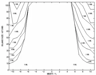
A phase diagram for the equilibrium shapes as a function of total number of island atoms N and lattice misfit f are shown in Fig. 2, for a short range potential corresponding to a cutoff radii rc=3.82 ˚A and rc=5.3 ˚A. Different phases are labelled by the total number of layers in the island. In agreement with previous works [1], there is a transition from a single layer configuration (uniform flat film) to an island configuration, above a critical size or lattice misfit. However, unlike the results from continuum elasticity theory, the phase diagram is not symmetric with respect to the misfit parameter and thus the behavior for compressive and tensile strained lay-ers is quite different. The asymmetry is more pronounced for a long range interaction potential, which includes significant contribution from next nearest neighbor atoms [16].
Comparing these results with those from the continuum elasticity theory [2], we note that there are two key parameters in Ref. [2]: r, the ratio of shallow to steep facet surface en-ergies, and the scaled volume V which depends on N and the misfit f in the combination N f4. The phase diagrams in Fig. 2 correspond to a fixed value of r. For the transition line from single layer to finite height island shape in our phase diagram, we find that the critical size along the transition line can be fit-ted to a power law as Nc∝f−a, with a≈3.8, consistent with the result from the continuum elasticity approach.
330 Brazilian Journal of Physics, vol. 36, no. 2A, June, 2006
2. Shape transition
We have also studied minimal energy paths for transitions from a flat layer to an island of finite height. For a fixed num-ber of atoms N and misfit f close to the transition, we con-sider two shapes corresponding to the different states across a transition line from 1 to 2 ML in Fig. 2. Given these as ini-tial and final states, we use the Nudged Elastic Band (NEB) [15] method to generate a (locally) minimum energy transition path between these two different shapes. We follow the simi-lar approach used in the study of defect nucleation in strained epitaxial films, introduced recently [14]. As an initial guess for the transition path we use a simple linear interpolation. The resulting energy profile and configurations along the min-imum energy path are shown in Fig. 3. As it is clear from the figure, there is a large energy barrier separating the two dis-tinct minima corresponding to the two different shapes. This is generally true for any two states bordering the transition line in our phase diagram in Fig. 2. Thus, depending on the time scale, the transition may occur too slowly to be observed during epitaxial growth. The existence of this large energy barrier, obtained with our atomistic model, supports the con-clusion from the elastic theory calculations [2, 3] that the tran-sition can be regarded as first order.
1 - initial
4
5
6
7
20 - final
0 5 10 15 20
0 2 4
1
23
4
5 6
7 8 9
10 11
12
13 1415
16 17
1819
20
reaction coordinate
∆∆∆∆
E (
e
V)
Fig. 3. Atomic configurations for the minimum energy path and energy profile (inset) across the shape transition boundary for flat layer to island shape.
3. Dislocation nucleation
For sufficiently large islands or misfits we find that relax-ing an initial configuration with MD coolrelax-ing already gener-ates dislocations in the lowest energy state. This implies that the energy barrier for dislocation nucleation is zero or neg-ligible above a critical value. We find that the dislocations nucleate from the edges of the adsorbate-substrate interface
for an initially dislocation-free island. This is in contrast with the mechanism for a flat uniform film [14], where dislocations nucleate from the top layer. This result provides a strong sup-port from atomistic calculations for the conclusions obtained within continuum elasticity theory [6, 7]. To better under-stand the dislocation nucleation mechanism, we consider a re-gion of phase space where the dislocation is not necessarily spontaneously generated, i.e., there may exist a finite barrier for nucleation. The transition path for dislocation nucleation is generated using the NEB approach [15] with the coherent island and the island with dislocation as the initial and final states. As a initial guess for the transition path we use again a simple linear interpolation scheme between the coherent and incoherent states. The resulting energy profile and configu-rations along the minimum energy path found are shown in Fig. 4. The sequence of configurations along the transition path shows that the a dislocation nucleates from the right edge of the island (Fig. 4b) and then propagate inwards. The en-ergy barrier for a fixed island size decreases with misfit. This is consistent with experimental results [10], which show that small islands are dislocation-free but dislocations appear in the island when it reaches a critical size.
A
B C
0 5 10 15 20 25 30 -1
0
f = 7%
C B
A
∆∆∆∆
E (
e
V)
reaction coordinate
Fig. 4. Atomic configurations for the minimum energy path and energy profile (inset) for dislocation nucleation. Closed path in (c) is the Burgers circuit around the dislocation core in the final state.
IV. CONCLUSIONS
J. Jalkanen et al. 331
method can also be extended to more realistic 3D systems.
Acknowledgments
This work has been supported in part by Fundac¸˜ao de
Am-paro `a Pesquisa do Estado de S˜ao Paulo - FAPESP (grant no. 03/00541-0) (E.G.) and the Academy of Finland through its Center of Excellence program (T.A-N.).
[1] P. Politi, G. Grenet, A. Marty, A. Ponchet, and J. Villain, Phys. Reports 324, 271 (2000).
[2] I. Daruka, J. Tersoff, and A.-L. Bara’b´asi, Phys. Rev. Lett. 82, 2753 (1999).
[3] I. Daruka and J. Tersoff, Phys. Rev. B 66, 132104 (2002). [4] L.G. Wang, P. Kratzer, N. Moll, and M. Scheffler, Phys. Rev. B
62, 1897 (2000).
[5] C. Ratsch and A. Zangwill, Surf. Sci. 293, 123 (1993). [6] H.T. Johnson and L.B. Freund, J. Appl. Phys. 81, 6081 (1997). [7] B.J. Spencer and J. Tersoff, Phys. Rev. B 63, 205424 (2001). [8] J. Tersoff and F.K. LeGoues, Phys. Rev. Lett. 72, 3570 (1994). [9] R. A. Budiman and H.E. Ruda, J. Appl. Phys. 88, 4586 (2000). [10] A. Ponchet, A. Le Corre, H. L’Haridon, B. Lambert, S. Salan, D. Alquier, D. Lacombe and L. Durand, Appl. Surf. Sci. 123, 751 (1998).
[11] H. Uemura, M. Uwaha, and Y. Saito, J. Phys. Soc. Japan 71,
1296 (2002).
[12] S. Zhen and G. J. Davies, Phys. Stat. Sol. A78, 595 (1983). [13] O. Trushin, E. Granato, S.-C. Ying, P. Salo and T. Ala-Nissila,
Phys. Stat. Sol. B, 232,100 (2002); O. Trushin, E. Granato, S.-C. Ying, J.M. Kosterlitz, T. Ala-Nissila and P. Salo, Braz. J. Phys. 32, 369 (2002).
[14] O. Trushin, E. Granato, S.-C. Ying, P. Salo and T. Ala-Nissila, Phys. Rev. B 65, 241408(R), (2002); Phys. Rev. B 68, 155413 (2003).
[15] H. J´onsson, G. Mills and K. W. Jacobsen, in Classical and
Quantum Dynamics in Condensed Phase Simulations, ed. by
B. J. Berne et al (World Scientific, Singapore, 1998).