Analysis of Composite Laminated Plates using
High-Order Shear Deformation Theories: a
Meshless Approach.
Solid Mechanics and Composite Materials Applications.
by
Daniel do Espírito Santo Rodrigues
Thesis submitted to
Faculdade de Engenharia da Universidade do Porto
as a requirement to obtain the MSc degree in Mechanical Engineering.
under the supervision of
Professor Jorge Américo Oliveira Pinto Belinha and
“I have no idea what I am doing but incompetence has never prevented me from plunging in with enthusiasm.”
Ao Professor Jorge Belinha, um obrigado pela oportunidade. Não me refiro apenas à oportunidade única de poder trabalhar sob orientação de alguém possuidor de tão vasto conhecimento e que sempre demonstrou um empenho e uma dedicação ímpares pelos seus alunos, mas sobretudo pela persistência em oferecer-me essa oportunidade. Ainda tenho vivas memórias da minha estupefação quando recebi um e-mail com uma proposta do Professor Jorge Belinha para fazer parte do seu grupo de investigação. Foi para mim um orgulho, e continuará sempre a sê-lo.
Ao Professor Renato Natal Jorge obrigado por me incutir uma paixão que julgava impossível pelos métodos numéricos e por reconhecer em mim capacidades suficientes para pertencer ao seu grupo de investigação. À Professora Lúcia Dinis, agradeço simpatia, a disponibilidade e sobretudo por me ter introduzido ao vasto universo das placas.
Um agradecimento especial também ao Professor António Torres Marques, ao Professor Paulo Tavares de Castro e ao Professor José Dias Rodrigues pelo entusiasmo com que lecionam as suas aulas e pelo imenso conhecimento que todos os dias partilham e fazem gerar.
À Isa, à Mariana e à Tania obrigado por estarem comigo há tantos anos e nunca se terem sentido tentadas a dizer um adeus definitivo. Obrigado pela amizade, pela companhia, pelo apoio, pelos risos compulsivos, pelas memórias. Sem vocês nada disto teria sido possível.
Um obrigado muito sentido aos meus companheiros da Magazine.HD, em especial ao Rui e à Catarina, por acreditarem não só nas minhas capacidades em termos de expressão escrita, mas sobretudo por reconhecerem nos meus pensamentos e ideias uma relevância que nunca antes tinha sentido. A cada dia que foi passando ao longo destes últimos cinco anos de percurso académico, foi naquele canto online plantado que reconheci que a Engenharia tinha no Cinema um rival à altura e que pretendo irremediavelmente viver em comunhão com ambos durante muitos anos.
Aos meus pais, mesmo que nem tudo tenha corrido como idealizado, obrigado por acreditarem sempre que aquele miúdo franzino de olhos fixados no seu Gameboy iria ser alguém. Obrigado pelos inúmeros incentivos e pelo orgulho reiterado.
The author truly acknowledge the funding provided by Ministério da Educação e Ciência – Fundação para a Ciência e a Tecnologia (Portugal), by project funding UID/EMS/50022/2013 - Advanced materials for noise reduction: modeling, optimization and experimental validation (funding provided by the inter-institutional projects from LAETA and INEGI).
The author truly acknowledge the work conditions provided by the Department of Mechanical Engineering from FEUP and INEGI.
Solid Mechanics and Composite Materials Applications. by
Daniel do Espírito Santo Rodrigues
Thesis submitted in fulfilment of the degree of Master of Science in Mechanical Engineering in the Faculdade de Engenharia da Universidade
do Porto under the supervision of:
Professor Jorge Américo Oliveira Pinto Belinha Professor of Faculdade de Engenharia da Universidade do Porto
and
Professor Aurélio Araújo
Associated Professor of Instituto Superior Técnico Professor Renato Natal Jorge
Associated Professor of Faculdade de Engenharia da Universidade do Porto
Abstract
Composite structures are commonly analysed using the Finite Element Method (FEM). However, new accurate and efficient discrete numerical techniques have appeared recently - the meshless methods. Thus, this work uses two meshless methods to perform an elasto-static analysis of composite laminated plates. Meshless methods only require an unstructured nodal distribution to discretize the problem domain. In order to numerically integrate the integro-differential equation from the Galerkin weak formulation, a background integration mesh is constructed. Then, the nodal connectivity is enforced using the influence-domain concept and the shape functions are obtained. In this work, the deformation field of the solid domain is ruled by several equivalent single layer theories, assuming different
Solid Mechanics and Composite Materials Applications. por
Daniel do Espírito Santo Rodrigues
Tese apresentada à Faculdade de Engenharia da Universidade do Porto, para a obtenção do grau de Mestre em Engenharia Mecânica, sob a
orientação de:
Professor Jorge Américo Oliveira Pinto Belinha Professor da Faculdade de Engenharia da Universidade do Porto
e
Professor Aurélio Araújo
Professor Associado do Instituto Superior Técnico Professor Renato Natal Jorge
Professor Associado da Faculdade de Engenharia da Universidade do Porto
Sumário
Estruturas compósitas são geralmente analisadas utilizando o Método dos Elementos Finitos (MEF). No entanto, novas técnicas de discretização numéricas, precisas e eficientes, têm aparecido recentemente - os métodos sem malha. Por conseguinte, este trabalho utiliza dois métodos sem malha para realizar análises elasto-estáticas de placas compósitas laminadas. Os métodos sem malha só exigem uma distribuição nodal não estruturada para discretizar o domínio do problema. A fim de integrar numericamente a equação integro-diferencial a partir da forma fraca de Galerkin, uma malha de integração é construída. Em seguida, a conectividade nodal é imposta utilizando o conceito de domínio de influência e as funções de forma são obtidas. O campo de deformação do domínio sólido é governado por modelos
Table of Contents
1 INTRODUCTION ... 1
1.1 MESHLESS METHODS ... 1
1.1.1 On the General Meshless Procedure ... 2
1.1.2 Relevant Meshless Methods ... 4
1.1.3 Radial Point Interpolation Method ... 5
1.1.4 The Natural Neighbour Radial Point Interpolation Method ... 5
1.2 LAMINATED COMPOSITE MATERIALS ... 6
1.3 HIGH-ORDER SHEAR DEFORMATION PLATE THEORIES ... 7
1.4 THESIS OBJECTIVES ... 8
1.5 THESIS ARRANGEMENT ... 9
2 MESHLESS METHODS ... 11
2.1 GENERIC PROCEDURE OF A MESHLESS METHOD ... 11
2.2 RADIAL POINT INTERPOLATION METHOD FORMULATION ... 14
2.2.1 Influence-Domains and Nodal Connectivity ... 14
2.2.2 Numerical Integration... 15
2.2.1 Interpolation Functions... 17
2.3 NATURAL NEIGHBOUR RADIAL POINT INTERPOLATION METHOD ... 22
2.3.1 Voronoï Diagram Concept and Natural Neighbours ... 22
2.3.2 Influence-Cells and Nodal Connectivity ... 24
2.3.3 Numerical Integration... 25
3 SOLID MECHANICS FUNDAMENTALS ... 29
3.1 GENERAL CONCEPTS OF STRAIN FIELD, STRESS TENSOR AND EQUILIBRIUM EQUATIONS ... 29
3.2 STRONG FORM AND WEAK FORM FORMULATIONS ... 30
3.2.1 Galerkin Weak Form ... 31
3.3 DISCRETE SYSTEM OF EQUATIONS ... 34
4 PLATES THEORY ... 39
4.1 BACKGROUND ... 39
4.2 CLASSICAL PLATE THEORY ... 42
4.2.1 Kirchhoff Assumptions ... 42
4.2.2 Kinematic Relations ... 43
4.2.3 Constitutive Equations ... 43
4.3 FIRST-ORDER SHEAR DEFORMATION THEORY (REISSER-MINDLIN PLATE THEORY) . 44 4.3.1 Mindlin Assumptions ... 44
4.3.2 Kinematic Relations ... 45
4.3.3 Constitutive Equations and Stress Resultants ... 46
4.3.4 Deformability Matrixes ... 49
4.3.5 Homogenised Constitutive Matrixes and Construction of the Global Stiffness Matrix 50 4.4 HIGH-ORDER SHEAR DEFORMATION THEORIES ... 52
Deformability Matrixes ... 63
Homogenised Constitutive Matrixes and Construction of the Global Stiffness Matrix ... 65
4.4.3 Touratier Plate Theory ... 69
Kinematic Relations ... 69
Deformability Matrixes ... 70
Homogenised Constitutive Matrixes and Construction of the Global Stiffness Matrix ... 72
4.4.4 Mantari Theory... 74
Kinematic Relations ... 75
Deformability Matrixes ... 76
Homogenised Constitutive Matrixes and Construction of the Global Stiffness Matrix ... 77
5 NUMERICAL EXAMPLES ... 81
5.1 ORTHOTROPIC PLATES AND SYMMETRIC CROSS-PLY LAMINATES ... 81
5.1.1 Introduction to the Problem Analysis ... 81
5.1.2 Considerations on the Generic Geometry ... 83
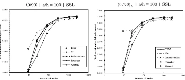
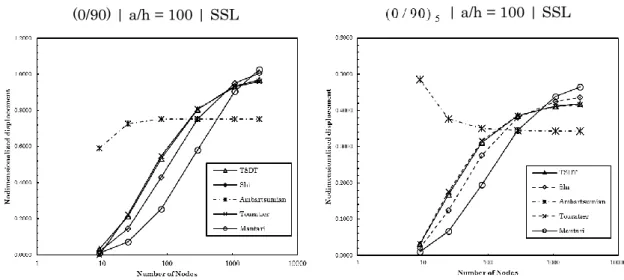
5.1.3 Convergence Studies ... 85
5.1.4 Solutions of Nondimensionalized Transverse Displacements and Stresses for Various Laminates ... 91
5.1.5 Nondimensionalized Maximum Stresses Along the Thickness for Various Laminates ... 99
5.1.6 Computation Time Study ... 106
5.1.7 Final Remarks ... 108
5.2 ANTISYMMETRIC CROSS-PLY LAMINATES ... 108
5.2.1 Introduction to the Problem Analysis ... 108
5.2.2 Considerations on the Generic Geometry ... 109
5.2.3 Convergence Studies ... 110
5.2.4 Solutions of Nondimensionalized Transverse Displacements and Stresses for Various Laminates ... 112
5.2.5 Study of the Influence of the Boundary Conditions ... 116
5.2.6 Nondimensionalized Maximum Stresses Along the Thickness for Various Laminates ... 118
5.2.7 Final Remarks ... 123
5.3 ANTISYMMETRIC ANGLE-PLY LAMINATES ... 123
5.3.1 Introduction to the Problem Analysis ... 123
5.3.2 Considerations on the Generic Geometry ... 124
5.3.3 Convergence Studies ... 124
5.3.4 Solutions of Nondimensionalized Transverse Displacements and Stresses for Various Laminates ... 127
5.3.5 Study of the Relation Between the Nondimensionalized Transverse Displacement and the Lamination Angle ... 129
5.3.6 Final Remarks ... 133
6 CONCLUSIONS ... 135
6.1 CONCLUSIONS AND REMARKS ... 135
6.2 FUTURE WORK ... 137
REFERENCES ... 139
APPENDIX ... 143
A. SOLUTIONS OF NONDIMENSIONALIZED TRANSVERSE DISPLACEMENTS AND STRESSES FOR VARIOUS LAMINATES ... 143
Orthotropic Plates and Symmetric Cross-Ply Laminates ... 143
Antisymmetric Cross-Ply Laminates ... 185
Antisymmetric Angle-Ply Laminates ... 200
B. NONDIMENSIONALIZED MAXIMUM STRESSES ALONG THE THICKNESS FOR VARIOUS LAMINATES ... 207
Symmetric Cross-Ply Laminates ... 207
List of Figures
FIGURE 1–NODAL DISCRETIZATION EXAMPLE.(A)IRREGULAR MESH.(B)REGULAR MESH. ... 12
FIGURE 2 – (A) FITTED GAUSSIAN INTEGRATION MESH. (B)GENERAL GAUSSIAN INTEGRATION MESH.(C)VORONOÏ DIAGRAM FOR NODAL INTEGRATION.[6] ... 12
FIGURE 3–(A)FIXED SIZE ‘INFLUENCE-DOMAIN’.(B)VARIABLE SIZE ‘INFLUENCE-DOMAIN’. ... 14
FIGURE 4 – SQUARE PLATE DISCRETIZED WITH 17X17 NODES (BLUE NODES) AND WITH A BACKGROUND INTEGRATION MESH WITH 2X2GAUSS POINTS (RED POINTS) IN EACH CELL. 15 FIGURE 5–(A)INITIAL NODAL SET OF POTENTIAL NEIGHBOUR NODES.(B)CONSTRUCTION OF THE CELL CONTAINING ONLY NEIGHBOUR NODES.(C)VORONOÏ CELL.(D)VORONOÏ DIAGRAM.[6] ... 23
FIGURE 6–(A)FIRST DEGREE INFLUENCE-CELL.(B)SECOND DEGREE INFLUENCE-CELL.[6]... 24
FIGURE 7–(A)INITIAL VORONOI DIAGRAM.(B)DELAUNAY TRIANGULATION.[6]... 25
FIGURE 8 – (A) VORONOÏ CELL AND THE RESPECTIVE PIi INTERSECTION POINTS. (B) MIDDLE POINTS M .Ii (C)QUADRILATERAL M P M nI3 I4 I4 I .[6] ... 26
FIGURE 9–(A)VORONOÏ CELL AND THE RESPECTIVEPIiINTERSECTION POINTS.(B)MIDDLE POINTS Ii M .(C)TRIANGLE M M nI8 I1 I .[6] ... 26
FIGURE 10 – (A) TRIANGULAR SHAPE AND (B) QUADRILATERAL SHAPE AND THE RESPECTIVE INTEGRATION POINTS XI.[6] ... 27
FIGURE 11–CONTINUOUS SOLID SUBJECT TO VOLUME FORCES AND EXTERNAL FORCES.[6] ... 32
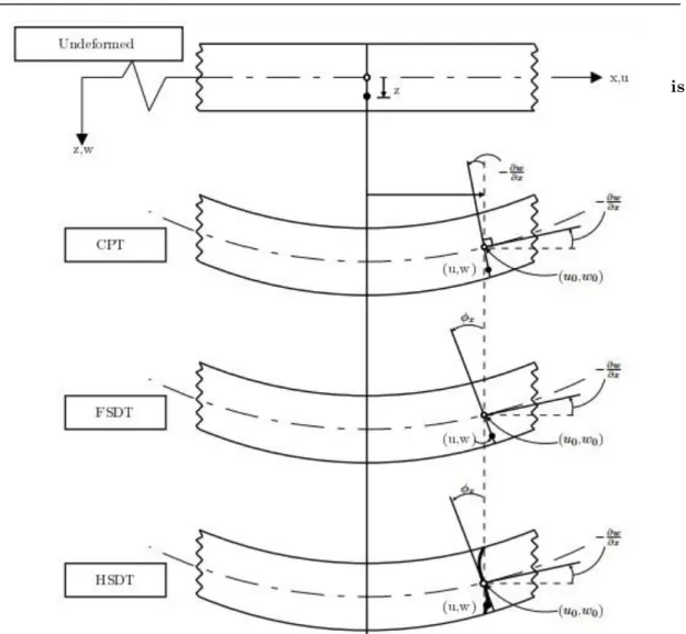
IS FIGURE 12–UNDEFORMED AND DEFORMED SECTION OF AN EDGE OF A PLATE IN DIFFERENT PLATE THEORIES.[35] ... 41
FIGURE 13–GENERAL PLATE SUBJECTED TO A BENDING LOAD. ... 42
FIGURE 14–(A)COMPOSITE LAMINATED PLATE WITH n LAYERS, EACH ONE WITH AN ORIENTATION OF ITS FIBRES;(B)VIEW FROM THE TOP OF THE LOCAL AXIS, Οx'y'. ... 46
FIGURE 15–COMPOSITE LAMINATE LAYER DISTRIBUTION. ... 48
FIGURE 16–DISTRIBUTION OF THE FUNCTION f z( )FOR DIFFERENT HSDTS AND ALSO FOR THE FSDT AS A FUNCTION OF THE NORMALIZED THICKNESS Z/H. ... 53
FIGURE 17– SYMMETRIC CROSS-PLY LAMINATE (0/90/90/0) AND THE CARTESIAN COORDINATE SYSTEM... 82
FIGURE 18–GENERAL GEOMETRY OF THE LAMINATED PLATES ANALYSED. ... 83
FIGURE 19–GENERAL LOAD q(x, y)... 83
FIGURE 20–LOCATIONS IN THE PLANE Oxy OF THE POINTS A,B,C AND D. ... 84
FIGURE 21 – CONVERGENCE STUDIES FOR THE RPIM WITH DIFFERENT TYPES OF PLATES, GEOMETRIES AND LOADS. TSDT IS THE THIRD-ORDER SHEAR DEFORMATION THEORY OF REDDY. ... 86
FIGURE 22–CONVERGENCE STUDIES FOR THE NNRPIM(V1) WITH DIFFERENT TYPES OF PLATES, GEOMETRIES AND LOADS. TSDT IS THE THIRD-ORDER SHEAR DEFORMATION THEORY OF REDDY. ... 87
FIGURE 23–CONVERGENCE STUDIES FOR THE NNRPIM(V2) WITH DIFFERENT TYPES OF PLATES, GEOMETRIES AND LOADS. TSDT IS THE THIRD-ORDER SHEAR DEFORMATION THEORY OF REDDY. ... 88
SUPPORTED (0/90/90/0) LAMINATE SUBJECTED TO A SINUSOIDAL LOAD (SSL) USING THE
RPIM. ... 94
FIGURE 27– RELATIVE ERRORS (%) REGARDING THE RESPECTIVE EXACT SOLUTION FOR THE MAXIMUM NORMALIZED TRANSVERSE DISPLACEMENTS AND NORMAL STRESSES FOR A SIMPLY SUPPORTED (0/90/90/0) LAMINATE SUBJECTED TO A SINUSOIDAL LOAD (SSL) USING THE
NNRPIMV1. ... 95
FIGURE 28– RELATIVE ERRORS (%) REGARDING THE RESPECTIVE EXACT SOLUTION FOR THE MAXIMUM IN-PLANE AND SHEAR STRESSES FOR A SIMPLY SUPPORTED (0/90/90/0) LAMINATE SUBJECTED TO A SINUSOIDAL LOAD (SSL) USING THE NNRPIMV1. ... 96 FIGURE 29– RELATIVE ERRORS (%) REGARDING THE RESPECTIVE EXACT SOLUTION FOR THE
MAXIMUM NORMALIZED TRANSVERSE DISPLACEMENTS AND NORMAL STRESSES FOR A SIMPLY SUPPORTED (0/90/90/0) LAMINATE SUBJECTED TO A SINUSOIDAL LOAD (SSL) USING THE
NNRPIMV2. ... 97
FIGURE 30– RELATIVE ERRORS (%) REGARDING THE RESPECTIVE EXACT SOLUTION FOR THE MAXIMUM IN-PLANE AND SHEAR STRESSES FOR A SIMPLY SUPPORTED (0/90/90/0) LAMINATE SUBJECTED TO A SINUSOIDAL LOAD (SSL) USING THE NNRPIMV2. ... 98 FIGURE 31 – NONDIMENSIONALIZED STRESSES xx COMPUTED WITH THE THREE NUMERICAL
METHODS FOR A SIMPLY SUPPORTED SYMMETRIC SQUARE LAMINATE WITH CROSS-PLY LAYERS (0/90/90/0) SUBJECTED TO A SINUSOIDAL LOAD (SSL), A/H=4. ... 101 FIGURE 32 – NONDIMENSIONALIZED STRESSES yy COMPUTED WITH THE THREE NUMERICAL
METHODS FOR A SIMPLY SUPPORTED SYMMETRIC SQUARE LAMINATE WITH CROSS-PLY LAYERS (0/90/90/0) SUBJECTED TO A SINUSOIDAL LOAD (SSL), A/H=4. ... 102 FIGURE 33 – NONDIMENSIONALIZED STRESSES yz COMPUTED WITH THE THREE NUMERICAL
METHODS FOR A SIMPLY SUPPORTED SYMMETRIC SQUARE LAMINATE WITH CROSS-PLY LAYERS (0/90/90/0) SUBJECTED TO A SINUSOIDAL LOAD (SSL), A/H=4. ... 103 FIGURE 34 – NONDIMENSIONALIZED STRESSES xz COMPUTED WITH THE THREE NUMERICAL
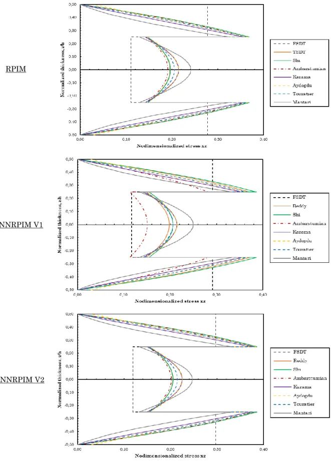
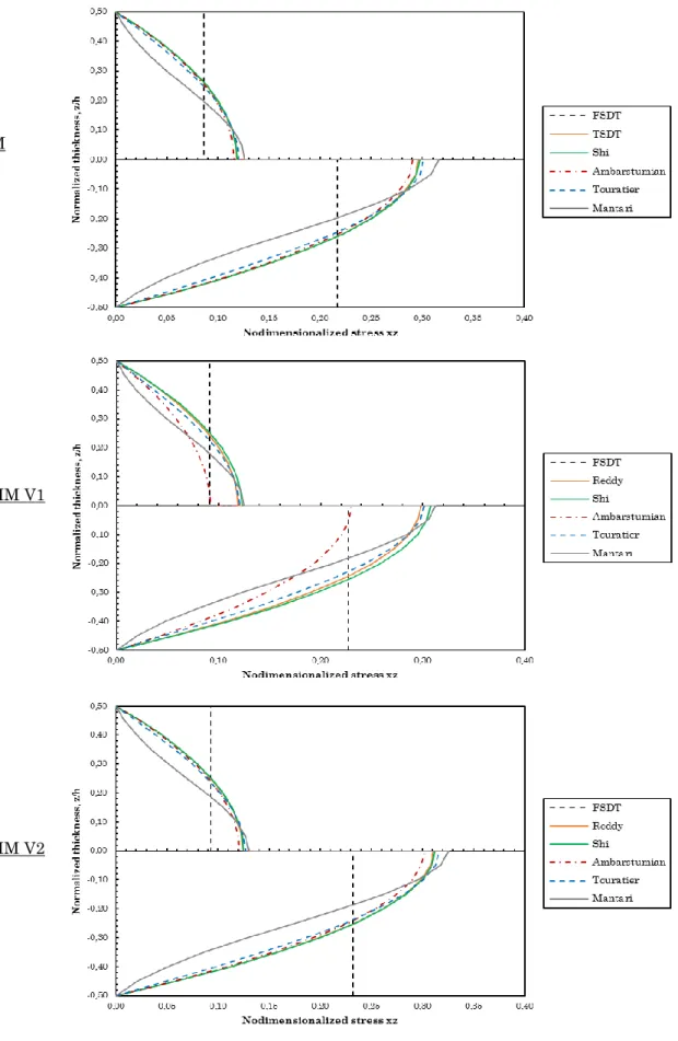
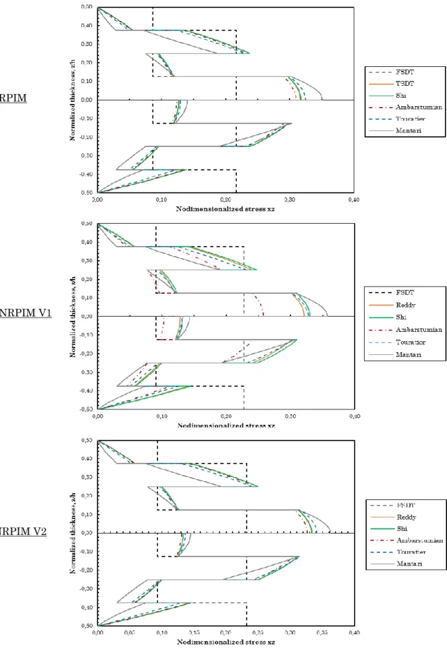
METHODS FOR A SIMPLY SUPPORTED SYMMETRIC SQUARE LAMINATE WITH CROSS-PLY LAYERS (0/90/90/0) SUBJECTED TO A SINUSOIDAL LOAD (SSL), A/H=4. ... 104
FIGURE 35–DETAILS FOR THE NONDIMENSIONALIZED NORMAL STRESSES yy COMPUTED WITH
THE RPIM FOR A SIMPLY SUPPORTED SYMMETRIC SQUARE LAMINATE WITH CROSS-PLY LAYERS (0/90/90/0) SUBJECTED TO A SINUSOIDAL LOAD (SSL).(A) A/H=4,(B) A/H=10 AND (C) A/H=100. ... 105 FIGURE 36–COMPUTATION TIME STUDY FOR THE SEVEN HSDTS COMPUTED WITH THE THREE
NUMERICAL METHODS. ... 107 FIGURE 37 – ANTISYMMETRIC CROSS-PLY LAMINATE (0/90) AND THE CARTESIAN COORDINATE
SYSTEM... 108 FIGURE 38–NOMENCLATURE ASSIGNED TO THE EDGES OF THE PLATE ... 109 FIGURE 39 – CONVERGENCE STUDIES FOR THE RPIM WITH TWO ANTISYMMETRIC CROSS-PLY
LAMINATES. ... 110
FIGURE 40–CONVERGENCE STUDIES FOR THE NNRPIMV1 WITH TWO ANTISYMMETRIC CROSS
-PLY LAMINATES. ... 111
FIGURE 41–CONVERGENCE STUDIES FOR THE NNRPIMV2 WITH TWO ANTISYMMETRIC CROSS
-PLY LAMINATES. ... 111
FIGURE 42 – MAXIMUM NORMALIZED TRANSVERSE DISPLACEMENTS AND STRESSES FOR TWO
ANTISYMMETRIC CROSS-PLY SQUARE LAMINATES -(0 / 90)nWITH N=1 AND N=5- SUBJECTED TO A SINUSOIDAL LOAD (SSL), WITH THE BOUNDARY CONDITIONS OF THE CASE 1, A/H=10.
SOLUTIONS FOR THE HSDTS COMPUTED WITH THE RPIM. ... 113
FIGURE 43 – MAXIMUM NORMALIZED TRANSVERSE DISPLACEMENTS AND STRESSES FOR TWO
ANTISYMMETRIC CROSS-PLY SQUARE LAMINATES -(0 / 90)nWITH N=1 AND N=5- SUBJECTED TO A SINUSOIDAL LOAD (SSL), WITH THE BOUNDARY CONDITIONS OF THE CASE 1, A/H=10.
SOLUTIONS FOR THE HSDTS COMPUTED WITH THE NNRPIMV1. ... 114
FIGURE 44 – MAXIMUM NORMALIZED TRANSVERSE DISPLACEMENTS AND STRESSES FOR TWO
TO A SINUSOIDAL LOAD (SSL), WITH THE BOUNDARY CONDITIONS OF THE CASE 1, A/H=10.
SOLUTIONS FOR THE HSDTS COMPUTED WITH THE NNRPIMV2. ... 115 FIGURE 45 – RELATIVE ERRORS (%) REGARDING THE EXACT SOLUTION OF THE MAXIMUM
NORMALIZED TRANSVERSE DISPLACEMENTS FOR TWO ANTISYMMETRIC CROSS-PLY SQUARE
LAMINATES -(0 / 90)n WITH N=1 AND N=5 - SUBJECTED TO A SINUSOIDAL LOAD (SSL),
A/H=10. ... 116 FIGURE 46–IMPOSITION OF THE ESSENTIAL BOUNDARY CONDITIONS FOR (A) TWO CLAMPED EDGES
OF THE PLATE;(B) ONLY THE RIGHT EDGE OF THE PLATE IS CLAMPED. ... 117 FIGURE 47 – NONDIMENSIONALIZED STRESSES yy COMPUTED WITH THE THREE NUMERICAL
METHODS FOR A SIMPLY SUPPORTED ANTISYMMETRIC SQUARE LAMINATE WITH CROSS-PLY
LAYERS (0/90) SUBJECTED TO A SINUSOIDAL LOAD (SSL), A/H=4. ... 119
FIGURE 48 – NONDIMENSIONALIZED STRESSES
xz COMPUTED WITH THE THREE NUMERICAL
METHODS FOR A SIMPLY SUPPORTED ANTISYMMETRIC SQUARE LAMINATE WITH CROSS-PLY
LAYERS (0/90) SUBJECTED TO A SINUSOIDAL LOAD (SSL), A/H=4. ... 120 FIGURE 49 – NONDIMENSIONALIZED STRESSES yy COMPUTED WITH THE THREE NUMERICAL
METHODS FOR A SIMPLY SUPPORTED ANTISYMMETRIC SQUARE LAMINATE WITH CROSS-PLY
LAYERS (0 / 90)4 SUBJECTED TO A SINUSOIDAL LOAD (SSL), A/H=4. ... 121
FIGURE 50 – NONDIMENSIONALIZED STRESSES xz COMPUTED WITH THE THREE NUMERICAL
METHODS FOR A SIMPLY SUPPORTED ANTISYMMETRIC SQUARE LAMINATE WITH CROSS-PLY
LAYERS (0 / 90)4 SUBJECTED TO A SINUSOIDAL LOAD (SSL), A/H=4. ... 122 FIGURE 51 – CONVERGENCE STUDIES FOR THE RPIM WITH TWO ANTISYMMETRIC ANGLE-PLY
LAMINATES. ... 125
FIGURE 52–CONVERGENCE STUDIES FOR THE NNRPIMV1 WITH TWO ANTISYMMETRIC ANGLE
-PLY LAMINATES. ... 126
FIGURE 53–CONVERGENCE STUDIES FOR THE NNRPIMV2 WITH TWO ANTISYMMETRIC ANGLE
-PLY LAMINATES. ... 127
FIGURE 54– RELATIVE ERRORS (%) REGARDING THE RESPECTIVE EXACT SOLUTION FOR THE MAXIMUM NORMALIZED TRANSVERSE DISPLACEMENTS FOR TWO SIMPLY SUPPORTED LAMINATED PLATES WITH ANTISYMMETRIC ANGLE-PLY LAYERS ( / )n SUBJECTED TO A SINUSOIDAL LOAD (SSL). ... 128
FIGURE 55-MAXIMUM NORMALIZED TRANSVERSE DISPLACEMENTS FOR TWO SIMPLY SUPPORTED
LAMINATED PLATES WITH ANTISYMMETRIC ANGLE-PLY LAYERS ( / )n SUBJECTED TO A SINUSOIDAL LOAD (SSL).DISPLACEMENTS AS A FUNCTION OF THE PLY ANGLE COMPUTED WITH THE RPIM, A/H=10. ... 130
FIGURE 56-MAXIMUM NORMALIZED TRANSVERSE DISPLACEMENTS FOR TWO SIMPLY SUPPORTED
LAMINATED PLATES WITH ANTISYMMETRIC ANGLE-PLY LAYERS ( / )n SUBJECTED TO A SINUSOIDAL LOAD (SSL).DISPLACEMENTS AS A FUNCTION OF THE PLY ANGLE COMPUTED WITH THE NNRPIMV1, A/H=10. ... 131
FIGURE 57-MAXIMUM NORMALIZED TRANSVERSE DISPLACEMENTS FOR TWO SIMPLY SUPPORTED
LAMINATED PLATES WITH ANTISYMMETRIC ANGLE-PLY LAYERS ( / )n SUBJECTED TO A SINUSOIDAL LOAD (SSL).DISPLACEMENTS AS A FUNCTION OF THE PLY ANGLE COMPUTED WITH THE NNRPIMV2, A/H=10. ... 132 FIGURE 58 – NONDIMENSIONALIZED STRESSES xx COMPUTED WITH THE THREE NUMERICAL
METHODS FOR A SIMPLY SUPPORTED SYMMETRIC SQUARE LAMINATE WITH CROSS-PLY LAYERS (0/90/0) SUBJECTED TO A SINUSOIDAL LOAD (SSL), A/H=4. ... 207
FIGURE 61 – NONDIMENSIONALIZED STRESSES xz COMPUTED WITH THE THREE NUMERICAL METHODS FOR A SIMPLY SUPPORTED SYMMETRIC SQUARE LAMINATE WITH CROSS-PLY LAYERS (0/90/0) SUBJECTED TO A SINUSOIDAL LOAD (SSL), A/H=4. ... 210
FIGURE 62 – NONDIMENSIONALIZED STRESSES xx COMPUTED WITH THE THREE NUMERICAL METHODS FOR A SIMPLY SUPPORTED SYMMETRIC SQUARE LAMINATE WITH CROSS-PLY LAYERS (0/90/0) SUBJECTED TO A SINUSOIDAL LOAD (SSL), A/H=10. ... 211 FIGURE 63 – NONDIMENSIONALIZED STRESSES yy COMPUTED WITH THE THREE NUMERICAL
METHODS FOR A SIMPLY SUPPORTED SYMMETRIC SQUARE LAMINATE WITH CROSS-PLY LAYERS (0/90/0) SUBJECTED TO A SINUSOIDAL LOAD (SSL), A/H=10. ... 212 FIGURE 64 – NONDIMENSIONALIZED STRESSES yz COMPUTED WITH THE THREE NUMERICAL
METHODS FOR A SIMPLY SUPPORTED SYMMETRIC SQUARE LAMINATE WITH CROSS-PLY LAYERS (0/90/0) SUBJECTED TO A SINUSOIDAL LOAD (SSL), A/H=10. ... 213 FIGURE 65 – NONDIMENSIONALIZED STRESSES xz COMPUTED WITH THE THREE NUMERICAL
METHODS FOR A SIMPLY SUPPORTED SYMMETRIC SQUARE LAMINATE WITH CROSS-PLY LAYERS (0/90/0) SUBJECTED TO A SINUSOIDAL LOAD (SSL), A/H=10. ... 214
FIGURE 66 – NONDIMENSIONALIZED STRESSES xx COMPUTED WITH THE THREE NUMERICAL METHODS FOR A SIMPLY SUPPORTED SYMMETRIC SQUARE LAMINATE WITH CROSS-PLY LAYERS (0/90/0) SUBJECTED TO A SINUSOIDAL LOAD (SSL), A/H=100. ... 215 FIGURE 67 – NONDIMENSIONALIZED STRESSES yy COMPUTED WITH THE THREE NUMERICAL
METHODS FOR A SIMPLY SUPPORTED SYMMETRIC SQUARE LAMINATE WITH CROSS-PLY LAYERS (0/90/0) SUBJECTED TO A SINUSOIDAL LOAD (SSL), A/H=100. ... 216 FIGURE 68 – NONDIMENSIONALIZED STRESSES yz COMPUTED WITH THE THREE NUMERICAL
METHODS FOR A SIMPLY SUPPORTED SYMMETRIC SQUARE LAMINATE WITH CROSS-PLY LAYERS (0/90/0) SUBJECTED TO A SINUSOIDAL LOAD (SSL), A/H=100. ... 217
FIGURE 69 – NONDIMENSIONALIZED STRESSES xz COMPUTED WITH THE THREE NUMERICAL METHODS FOR A SIMPLY SUPPORTED SYMMETRIC SQUARE LAMINATE WITH CROSS-PLY LAYERS (0/90/0) SUBJECTED TO A SINUSOIDAL LOAD (SSL), A/H=100. ... 218
FIGURE 70 – NONDIMENSIONALIZED STRESSES xx COMPUTED WITH THE THREE NUMERICAL METHODS FOR A SIMPLY SUPPORTED SYMMETRIC SQUARE LAMINATE WITH CROSS-PLY LAYERS (0/90/90/0) SUBJECTED TO A SINUSOIDAL LOAD (SSL), A/H=10. ... 219 FIGURE 71 – NONDIMENSIONALIZED STRESSES yy COMPUTED WITH THE THREE NUMERICAL
METHODS FOR A SIMPLY SUPPORTED SYMMETRIC SQUARE LAMINATE WITH CROSS-PLY LAYERS (0/90/90/0) SUBJECTED TO A SINUSOIDAL LOAD (SSL), A/H=10. ... 220 FIGURE 72 – NONDIMENSIONALIZED STRESSES yz COMPUTED WITH THE THREE NUMERICAL
METHODS FOR A SIMPLY SUPPORTED SYMMETRIC SQUARE LAMINATE WITH CROSS-PLY LAYERS (0/90/90/0) SUBJECTED TO A SINUSOIDAL LOAD (SSL), A/H=10. ... 221 FIGURE 73 – NONDIMENSIONALIZED STRESSES xz COMPUTED WITH THE THREE NUMERICAL
METHODS FOR A SIMPLY SUPPORTED SYMMETRIC SQUARE LAMINATE WITH CROSS-PLY LAYERS (0/90/90/0) SUBJECTED TO A SINUSOIDAL LOAD (SSL), A/H=10. ... 222 FIGURE 74 – NONDIMENSIONALIZED STRESSES xx COMPUTED WITH THE THREE NUMERICAL
METHODS FOR A SIMPLY SUPPORTED SYMMETRIC SQUARE LAMINATE WITH CROSS-PLY LAYERS (0/90/90/0) SUBJECTED TO A SINUSOIDAL LOAD (SSL), A/H=100. ... 223 FIGURE 75 – NONDIMENSIONALIZED STRESSES yy COMPUTED WITH THE THREE NUMERICAL
METHODS FOR A SIMPLY SUPPORTED SYMMETRIC SQUARE LAMINATE WITH CROSS-PLY LAYERS (0/90/90/0) SUBJECTED TO A SINUSOIDAL LOAD (SSL), A/H=100. ... 224 FIGURE 76 – NONDIMENSIONALIZED STRESSES yz COMPUTED WITH THE THREE NUMERICAL
METHODS FOR A SIMPLY SUPPORTED SYMMETRIC SQUARE LAMINATE WITH CROSS-PLY
FIGURE 77 – NONDIMENSIONALIZED STRESSES xz COMPUTED WITH THE THREE NUMERICAL METHODS FOR A SIMPLY SUPPORTED SYMMETRIC SQUARE LAMINATE WITH CROSS-PLY LAYERS (0/90/90/0) SUBJECTED TO A SINUSOIDAL LOAD (SSL), A/H=100. ... 226
FIGURE 78 – NONDIMENSIONALIZED STRESSES xx COMPUTED WITH THE THREE NUMERICAL METHODS FOR A SIMPLY SUPPORTED SYMMETRIC SQUARE LAMINATE WITH CROSS-PLY LAYERS (0/90/0/90/0) SUBJECTED TO A SINUSOIDAL LOAD (SSL), A/H=4. ... 227 FIGURE 79 – NONDIMENSIONALIZED STRESSES yy COMPUTED WITH THE THREE NUMERICAL
METHODS FOR A SIMPLY SUPPORTED SYMMETRIC SQUARE LAMINATE WITH CROSS-PLY LAYERS (0/90/0/90/0) SUBJECTED TO A SINUSOIDAL LOAD (SSL), A/H=4. ... 228 FIGURE 80 – NONDIMENSIONALIZED STRESSES yz COMPUTED WITH THE THREE NUMERICAL
METHODS FOR A SIMPLY SUPPORTED SYMMETRIC SQUARE LAMINATE WITH CROSS-PLY LAYERS (0/90/0/90/0) SUBJECTED TO A SINUSOIDAL LOAD (SSL), A/H=4. ... 229 FIGURE 81 – NONDIMENSIONALIZED STRESSES xz COMPUTED WITH THE THREE NUMERICAL
METHODS FOR A SIMPLY SUPPORTED SYMMETRIC SQUARE LAMINATE WITH CROSS-PLY LAYERS (0/90/0/90/0) SUBJECTED TO A SINUSOIDAL LOAD (SSL), A/H=4. ... 230
FIGURE 82 – NONDIMENSIONALIZED STRESSES xx COMPUTED WITH THE THREE NUMERICAL METHODS FOR A SIMPLY SUPPORTED SYMMETRIC SQUARE LAMINATE WITH CROSS-PLY LAYERS (0/90/0/90/0) SUBJECTED TO A SINUSOIDAL LOAD (SSL), A/H=10. ... 231 FIGURE 83 – NONDIMENSIONALIZED STRESSES yy COMPUTED WITH THE THREE NUMERICAL
METHODS FOR A SIMPLY SUPPORTED SYMMETRIC SQUARE LAMINATE WITH CROSS-PLY LAYERS (0/90/0/90/0) SUBJECTED TO A SINUSOIDAL LOAD (SSL), A/H=10. ... 232 FIGURE 84 – NONDIMENSIONALIZED STRESSES yz COMPUTED WITH THE THREE NUMERICAL
METHODS FOR A SIMPLY SUPPORTED SYMMETRIC SQUARE LAMINATE WITH CROSS-PLY LAYERS (0/90/0/90/0) SUBJECTED TO A SINUSOIDAL LOAD (SSL), A/H=10. ... 233
FIGURE 85 – NONDIMENSIONALIZED STRESSES xz COMPUTED WITH THE THREE NUMERICAL METHODS FOR A SIMPLY SUPPORTED SYMMETRIC SQUARE LAMINATE WITH CROSS-PLY LAYERS (0/90/0/90/0) SUBJECTED TO A SINUSOIDAL LOAD (SSL), A/H=10. ... 234
FIGURE 86 – NONDIMENSIONALIZED STRESSES xx COMPUTED WITH THE THREE NUMERICAL METHODS FOR A SIMPLY SUPPORTED SYMMETRIC SQUARE LAMINATE WITH CROSS-PLY LAYERS (0/90/0/90/0) SUBJECTED TO A SINUSOIDAL LOAD (SSL), A/H=100. ... 235 FIGURE 87 – NONDIMENSIONALIZED STRESSES yy COMPUTED WITH THE THREE NUMERICAL
METHODS FOR A SIMPLY SUPPORTED SYMMETRIC SQUARE LAMINATE WITH CROSS-PLY LAYERS (0/90/0/90/0) SUBJECTED TO A SINUSOIDAL LOAD (SSL), A/H=100. ... 236 FIGURE 88 – NONDIMENSIONALIZED STRESSES yz COMPUTED WITH THE THREE NUMERICAL
METHODS FOR A SIMPLY SUPPORTED SYMMETRIC SQUARE LAMINATE WITH CROSS-PLY LAYERS (0/90/0/90/0) SUBJECTED TO A SINUSOIDAL LOAD (SSL), A/H=100. ... 237 FIGURE 89 – NONDIMENSIONALIZED STRESSES xz COMPUTED WITH THE THREE NUMERICAL
METHODS FOR A SIMPLY SUPPORTED SYMMETRIC SQUARE LAMINATE WITH CROSS-PLY LAYERS (0/90/0/90/0) SUBJECTED TO A SINUSOIDAL LOAD (SSL), A/H=100. ... 238 FIGURE 90 – NONDIMENSIONALIZED STRESSES xx COMPUTED WITH THE THREE NUMERICAL
METHODS FOR A SIMPLY SUPPORTED SYMMETRIC SQUARE LAMINATE WITH CROSS-PLY LAYERS (0/90/90/0/90/90/0) SUBJECTED TO A SINUSOIDAL LOAD (SSL), A/H=4. ... 239
FIGURE 93 – NONDIMENSIONALIZED STRESSES xz COMPUTED WITH THE THREE NUMERICAL METHODS FOR A SIMPLY SUPPORTED SYMMETRIC SQUARE LAMINATE WITH CROSS-PLY LAYERS (0/90/90/0/90/90/0) SUBJECTED TO A SINUSOIDAL LOAD (SSL), A/H=4. ... 242
FIGURE 94 – NONDIMENSIONALIZED STRESSES xx COMPUTED WITH THE THREE NUMERICAL METHODS FOR A SIMPLY SUPPORTED SYMMETRIC SQUARE LAMINATE WITH CROSS-PLY LAYERS (0/90/90/0/90/90/0) SUBJECTED TO A SINUSOIDAL LOAD (SSL), A/H=10. ... 243 FIGURE 95 – NONDIMENSIONALIZED STRESSES yy COMPUTED WITH THE THREE NUMERICAL
METHODS FOR A SIMPLY SUPPORTED SYMMETRIC SQUARE LAMINATE WITH CROSS-PLY LAYERS (0/90/90/0/90/90/0) SUBJECTED TO A SINUSOIDAL LOAD (SSL), A/H=10. ... 244 FIGURE 96 – NONDIMENSIONALIZED STRESSES yz COMPUTED WITH THE THREE NUMERICAL
METHODS FOR A SIMPLY SUPPORTED SYMMETRIC SQUARE LAMINATE WITH CROSS-PLY LAYERS (0/90/90/0/90/90/0) SUBJECTED TO A SINUSOIDAL LOAD (SSL), A/H=10. ... 245 FIGURE 97 – NONDIMENSIONALIZED STRESSES xz COMPUTED WITH THE THREE NUMERICAL
METHODS FOR A SIMPLY SUPPORTED SYMMETRIC SQUARE LAMINATE WITH CROSS-PLY LAYERS (0/90/90/0/90/90/0) SUBJECTED TO A SINUSOIDAL LOAD (SSL), A/H=10. ... 246
FIGURE 98 – NONDIMENSIONALIZED STRESSES xx COMPUTED WITH THE THREE NUMERICAL METHODS FOR A SIMPLY SUPPORTED SYMMETRIC SQUARE LAMINATE WITH CROSS-PLY LAYERS (0/90/90/0/90/90/0) SUBJECTED TO A SINUSOIDAL LOAD (SSL), A/H=100. ... 247 FIGURE 99 – NONDIMENSIONALIZED STRESSES yy COMPUTED WITH THE THREE NUMERICAL
METHODS FOR A SIMPLY SUPPORTED SYMMETRIC SQUARE LAMINATE WITH CROSS-PLY LAYERS (0/90/90/0/90/90/0) SUBJECTED TO A SINUSOIDAL LOAD (SSL), A/H=100. ... 248 FIGURE 100 – NONDIMENSIONALIZED STRESSES yz COMPUTED WITH THE THREE NUMERICAL
METHODS FOR A SIMPLY SUPPORTED SYMMETRIC SQUARE LAMINATE WITH CROSS-PLY LAYERS (0/90/90/0/90/90/0) SUBJECTED TO A SINUSOIDAL LOAD (SSL), A/H=100. ... 249
FIGURE 101 – NONDIMENSIONALIZED STRESSES xz COMPUTED WITH THE THREE NUMERICAL METHODS FOR A SIMPLY SUPPORTED SYMMETRIC SQUARE LAMINATE WITH CROSS-PLY LAYERS (0/90/90/0/90/90/0) SUBJECTED TO A SINUSOIDAL LOAD (SSL), A/H=100. ... 250
FIGURE 102– NONDIMENSIONALIZED STRESSES yy COMPUTED WITH THE THREE NUMERICAL
METHODS FOR A SIMPLY SUPPORTED ANTISYMMETRIC SQUARE LAMINATE WITH CROSS-PLY
LAYERS (0/90) SUBJECTED TO A SINUSOIDAL LOAD (SSL), A/H=10. ... 251 FIGURE 103 – NONDIMENSIONALIZED STRESSES xz COMPUTED WITH THE THREE NUMERICAL
METHODS FOR A SIMPLY SUPPORTED ANTISYMMETRIC SQUARE LAMINATE WITH CROSS-PLY
LAYERS (0/90) SUBJECTED TO A SINUSOIDAL LOAD (SSL), A/H=10. ... 252 FIGURE 104– NONDIMENSIONALIZED STRESSES yy COMPUTED WITH THE THREE NUMERICAL
METHODS FOR A SIMPLY SUPPORTED ANTISYMMETRIC SQUARE LAMINATE WITH CROSS-PLY
LAYERS (0/90) SUBJECTED TO A SINUSOIDAL LOAD (SSL), A/H=100. ... 253 FIGURE 105 – NONDIMENSIONALIZED STRESSES xz COMPUTED WITH THE THREE NUMERICAL
METHODS FOR A SIMPLY SUPPORTED ANTISYMMETRIC SQUARE LAMINATE WITH CROSS-PLY
LAYERS (0/90) SUBJECTED TO A SINUSOIDAL LOAD (SSL), A/H=100. ... 254 FIGURE 106– NONDIMENSIONALIZED STRESSES yy COMPUTED WITH THE THREE NUMERICAL
METHODS FOR A SIMPLY SUPPORTED ANTISYMMETRIC SQUARE LAMINATE WITH CROSS-PLY
LAYERS (0 / 90)4 SUBJECTED TO A SINUSOIDAL LOAD (SSL), A/H=10. ... 255 FIGURE 107 – NONDIMENSIONALIZED STRESSES xz COMPUTED WITH THE THREE NUMERICAL
METHODS FOR A SIMPLY SUPPORTED ANTISYMMETRIC SQUARE LAMINATE WITH CROSS-PLY
LAYERS (0 / 90)4 SUBJECTED TO A SINUSOIDAL LOAD (SSL), A/H=10. ... 256
FIGURE 108– NONDIMENSIONALIZED STRESSES yy COMPUTED WITH THE THREE NUMERICAL
FIGURE 109 – NONDIMENSIONALIZED STRESSES xz COMPUTED WITH THE THREE NUMERICAL
METHODS FOR A SIMPLY SUPPORTED ANTISYMMETRIC SQUARE LAMINATE WITH CROSS-PLY
List of Tables
TABLE 1 – INTEGRATION POINTS AND CORRESPONDENT WEIGHTS FOR QUADRILATERAL
ISOPARAMETRIC CELLS (INTEGRATION WITH ONE, FOUR AND NINE GUASS-LEGENDRE INTEGRATION POINTS). ... 16
TABLE 2–HSDTS TO IMPLEMENT IN THE ALGORITHMS OF THE RPIM AND NNRPIM FOR STATIC
ANALYSIS OF COMPOSITE LAMINATED PLATES. ... 53 TABLE 3–CONSTANTS
1 k AND
2
k FOR THREE TSDTS. ... 54
TABLE 4–MECHANICAL PROPERTIES OF THE MATERIAL USED FOR ALL THE STATIC ANALYSIS OF
SYMMETRIC CROSS-PLY LAMINATES. ... 82
TABLE 5– Z COORDINATE WHERE THE NONDIMENSIONALIZED TRANSVERSE DISPLACEMENT AND
STRESSES ARE COMPUTED. ... 84
TABLE 6–RPIM AND NNRPIM PARAMETERS. ... 85
TABLE 7 – CONSIDERED BOUNDARY CONDITIONS:S =SIMPLY SUPPORTED;C= CLAMPED;F = FREE. ... 109
TABLE 8– Z COORDINATE WHERE THE NONDIMENSIONALIZED TRANSVERSE DISPLACEMENT AND
STRESSES ARE COMPUTED. ... 110
TABLE 9–MECHANICAL PROPERTIES OF THE MATERIAL USED FOR ALL THE STATIC ANALYSIS OF
ANTISYMMETRIC ANGLE-PLY LAMINATES. ... 123
TABLE 10– Z COORDINATE WHERE THE NONDIMENSIONALIZED TRANSVERSE DISPLACEMENT AND
STRESSES ARE COMPUTED. ... 124
TABLE 11-MAXIMUM NORMALIZED TRANSVERSE DISPLACEMENTS AND STRESSES FOR A SIMPLY
SUPPORTED ORTHOTROPIC PLATE SUBJECTED TO A SINUSOIDAL LOAD (SSL), A/H=4. ... 143
TABLE 12-MAXIMUM NORMALIZED TRANSVERSE DISPLACEMENTS AND STRESSES FOR A SIMPLY
SUPPORTED ORTHOTROPIC PLATE SUBJECTED TO A SINUSOIDAL LOAD (SSL), A/H=10. .... 144
TABLE 13-MAXIMUM NORMALIZED TRANSVERSE DISPLACEMENTS AND STRESSES FOR A SIMPLY
SUPPORTED ORTHOTROPIC PLATE SUBJECTED TO A SINUSOIDAL LOAD (SSL), A/H=20 ... 145
TABLE 14-MAXIMUM NORMALIZED TRANSVERSE DISPLACEMENTS AND STRESSES FOR A SIMPLY
SUPPORTED ORTHOTROPIC PLATE SUBJECTED TO A SINUSOIDAL LOAD (SSL), A/H=100. .. 146
TABLE 15-MAXIMUM NORMALIZED TRANSVERSE DISPLACEMENTS AND STRESSES FOR A SIMPLY
SUPPORTED ORTHOTROPIC PLATE SUBJECTED TO A UNIFORMLY DISTRIBUTED LOAD (UDL),
A/H=4. ... 147
TABLE 16-MAXIMUM NORMALIZED TRANSVERSE DISPLACEMENTS AND STRESSES FOR A SIMPLY
SUPPORTED ORTHOTROPIC PLATE SUBJECTED TO A UNIFORMLY DISTRIBUTED LOAD (UDL),
A/H=10. ... 148
TABLE 17-MAXIMUM NORMALIZED TRANSVERSE DISPLACEMENTS AND STRESSES FOR A SIMPLY
SUPPORTED ORTHOTROPIC PLATE SUBJECTED TO A UNIFORMLY DISTRIBUTED LOAD (UDL),
A/H=20. ... 149
TABLE 18-MAXIMUM NORMALIZED TRANSVERSE DISPLACEMENTS AND STRESSES FOR A SIMPLY
SUPPORTED ORTHOTROPIC PLATE SUBJECTED TO A UNIFORMLY DISTRIBUTED LOAD (UDL),
A/H=100. ... 150
TABLE 19-MAXIMUM NORMALIZED TRANSVERSE DISPLACEMENTS AND STRESSES AND RELATIVE
ERRORS IN RELATION TO THE RESPECTIVE EXACT SOLUTION FOR A SIMPLY SUPPORTED SYMMETRIC SQUARE LAMINATE WITH CROSS-PLY LAYERS (0/90/0) SUBJECTED TO A SINUSOIDAL LOAD (SSL), A/H=4. ... 151
SYMMETRIC SQUARE LAMINATE WITH CROSS-PLY LAYERS (0/90/0) SUBJECTED TO A SINUSOIDAL LOAD (SSL), A/H=20. ... 153
TABLE 22-MAXIMUM NORMALIZED TRANSVERSE DISPLACEMENTS AND STRESSES AND RELATIVE
ERRORS IN RELATION TO THE RESPECTIVE EXACT SOLUTION FOR A SIMPLY SUPPORTED SYMMETRIC SQUARE LAMINATE WITH CROSS-PLY LAYERS (0/90/0) SUBJECTED TO A SINUSOIDAL LOAD (SSL), A/H=100. ... 154
TABLE 23-MAXIMUM NORMALIZED TRANSVERSE DISPLACEMENTS AND STRESSES AND RELATIVE
ERRORS IN RELATION TO THE RESPECTIVE EXACT SOLUTION FOR A SIMPLY SUPPORTED SYMMETRIC RECTANGULAR (B=3A) LAMINATE WITH CROSS-PLY LAYERS (0/90/0) SUBJECTED TO A SINUSOIDAL LOAD (SSL), A/H=4,10. ... 155
TABLE 24-MAXIMUM NORMALIZED TRANSVERSE DISPLACEMENTS AND STRESSES AND RELATIVE
ERRORS IN RELATION TO THE RESPECTIVE EXACT SOLUTION FOR A SIMPLY SUPPORTED SYMMETRIC RECTANGULAR (B=3A) LAMINATE WITH CROSS-PLY LAYERS (0/90/0) SUBJECTED TO A SINUSOIDAL LOAD (SSL), A/H=20,100. ... 156
TABLE 25-MAXIMUM NORMALIZED TRANSVERSE DISPLACEMENTS AND STRESSES FOR A SIMPLY
SUPPORTED SYMMETRIC SQUARE LAMINATE WITH CROSS-PLY LAYERS (0/90/0) SUBJECTED TO A UNIFORMLY DISTRIBUTED LOAD (UDL), A/H=4. ... 157
TABLE 26-MAXIMUM NORMALIZED TRANSVERSE DISPLACEMENTS AND STRESSES FOR A SIMPLY
SUPPORTED SYMMETRIC SQUARE LAMINATE WITH CROSS-PLY LAYERS (0/90/0) SUBJECTED TO A UNIFORMLY DISTRIBUTED LOAD (UDL), A/H=10 ... 158
TABLE 27-MAXIMUM NORMALIZED TRANSVERSE DISPLACEMENTS AND STRESSES FOR A SIMPLY
SUPPORTED SYMMETRIC SQUARE LAMINATE WITH CROSS-PLY LAYERS (0/90/0) SUBJECTED TO A UNIFORMLY DISTRIBUTED LOAD (UDL), A/H=20 ... 159
TABLE 28- MAXIMUM NORMALIZED TRANSVERSE DISPLACEMENTS AND STRESSES FOR A SIMPLY
SUPPORTED SYMMETRIC SQUARE LAMINATE WITH CROSS-PLY LAYERS (0/90/0) SUBJECTED TO A UNIFORMLY DISTRIBUTED LOAD (UDL), A/H=100. ... 160
TABLE 29-MAXIMUM NORMALIZED TRANSVERSE DISPLACEMENTS AND STRESSES AND RELATIVE
ERRORS IN RELATION TO THE RESPECTIVE EXACT SOLUTION FOR A SIMPLY SUPPORTED SYMMETRIC SQUARE LAMINATE WITH CROSS-PLY LAYERS (0/90/90/0) SUBJECTED TO A SINUSOIDAL LOAD (SSL), A/H=4. ... 161
TABLE 30-MAXIMUM NORMALIZED TRANSVERSE DISPLACEMENTS AND STRESSES AND RELATIVE
ERRORS IN RELATION TO THE RESPECTIVE EXACT SOLUTION FOR A SIMPLY SUPPORTED SYMMETRIC SQUARE LAMINATE WITH CROSS-PLY LAYERS (0/90/90/0) SUBJECTED TO A SINUSOIDAL LOAD (SSL), A/H=10. ... 162
TABLE 31-MAXIMUM NORMALIZED TRANSVERSE DISPLACEMENTS AND STRESSES AND RELATIVE
ERRORS IN RELATION TO THE RESPECTIVE EXACT SOLUTION FOR A SIMPLY SUPPORTED SYMMETRIC SQUARE LAMINATE WITH CROSS-PLY LAYERS (0/90/90/0) SUBJECTED TO A SINUSOIDAL LOAD (SSL), A/H=20. ... 163
TABLE 32-MAXIMUM NORMALIZED TRANSVERSE DISPLACEMENTS AND STRESSES AND RELATIVE
ERRORS IN RELATION TO THE RESPECTIVE EXACT SOLUTION FOR A SIMPLY SUPPORTED SYMMETRIC SQUARE LAMINATE WITH CROSS-PLY LAYERS (0/90/90/0) SUBJECTED TO A SINUSOIDAL LOAD (SSL), A/H=100. ... 164
TABLE 33-MAXIMUM NORMALIZED TRANSVERSE DISPLACEMENTS AND STRESSES FOR A SIMPLY
SUPPORTED SYMMETRIC SQUARE LAMINATE WITH CROSS-PLY LAYERS (0/90/90/0) SUBJECTED TO A UNIFORMLY DISTRIBUTED LOAD (UDL), A/H=4. ... 165
TABLE 34-MAXIMUM NORMALIZED TRANSVERSE DISPLACEMENTS AND STRESSES FOR A SIMPLY
SUPPORTED SYMMETRIC SQUARE LAMINATE WITH CROSS-PLY LAYERS (0/90/90/0) SUBJECTED TO A UNIFORMLY DISTRIBUTED LOAD (UDL), A/H=10. ... 166
TABLE 35-MAXIMUM NORMALIZED TRANSVERSE DISPLACEMENTS AND STRESSES FOR A SIMPLY
SUPPORTED SYMMETRIC SQUARE LAMINATE WITH CROSS-PLY LAYERS (0/90/90/0) SUBJECTED TO A UNIFORMLY DISTRIBUTED LOAD (UDL), A/H=20. ... 167
TABLE 36-MAXIMUM NORMALIZED TRANSVERSE DISPLACEMENTS AND STRESSES FOR A SIMPLY
SUPPORTED SYMMETRIC SQUARE LAMINATE WITH CROSS-PLY LAYERS (0/90/90/0) SUBJECTED TO A UNIFORMLY DISTRIBUTED LOAD (UDL), A/H=100. ... 168
TABLE 37-MAXIMUM NORMALIZED TRANSVERSE DISPLACEMENTS AND STRESSES FOR A SIMPLY
SUPPORTED SYMMETRIC SQUARE LAMINATE WITH CROSS-PLY LAYERS (0/90/0/90/0)
TABLE 38-MAXIMUM NORMALIZED TRANSVERSE DISPLACEMENTS AND STRESSES FOR A SIMPLY
SUPPORTED SYMMETRIC SQUARE LAMINATE WITH CROSS-PLY LAYERS (0/90/0/90/0)
SUBJECTED TO A SINUSOIDAL LOAD (SSL), A/H=10. ... 170
TABLE 39-MAXIMUM NORMALIZED TRANSVERSE DISPLACEMENTS AND STRESSES FOR A SIMPLY
SUPPORTED SYMMETRIC SQUARE LAMINATE WITH CROSS-PLY LAYERS (0/90/0/90/0)
SUBJECTED TO A SINUSOIDAL LOAD (SSL), A/H=20. ... 171
TABLE 40-MAXIMUM NORMALIZED TRANSVERSE DISPLACEMENTS AND STRESSES FOR A SIMPLY
SUPPORTED SYMMETRIC SQUARE LAMINATE WITH CROSS-PLY LAYERS (0/90/0/90/0)
SUBJECTED TO A SINUSOIDAL LOAD (SSL), A/H=100. ... 172
TABLE 41-MAXIMUM NORMALIZED TRANSVERSE DISPLACEMENTS AND STRESSES FOR A SIMPLY
SUPPORTED SYMMETRIC SQUARE LAMINATE WITH CROSS-PLY LAYERS (0/90/0/90/0)
SUBJECTED TO A UNIFORMLY DISTRIBUTED LOAD (UDL), A/H=4. ... 173
TABLE 42-MAXIMUM NORMALIZED TRANSVERSE DISPLACEMENTS AND STRESSES FOR A SIMPLY
SUPPORTED SYMMETRIC SQUARE LAMINATE WITH CROSS-PLY LAYERS (0/90/0/90/0)
SUBJECTED TO A UNIFORMLY DISTRIBUTED LOAD (UDL), A/H=10. ... 174
TABLE 43-MAXIMUM NORMALIZED TRANSVERSE DISPLACEMENTS AND STRESSES FOR A SIMPLY
SUPPORTED SYMMETRIC SQUARE LAMINATE WITH CROSS-PLY LAYERS (0/90/0/90/0)
SUBJECTED TO A UNIFORMLY DISTRIBUTED LOAD (UDL), A/H=20. ... 175
TABLE 44-MAXIMUM NORMALIZED TRANSVERSE DISPLACEMENTS AND STRESSES FOR A SIMPLY
SUPPORTED SYMMETRIC SQUARE LAMINATE WITH CROSS-PLY LAYERS (0/90/0/90/0)
SUBJECTED TO A UNIFORMLY DISTRIBUTED LOAD (UDL), A/H=100. ... 176
TABLE 45-MAXIMUM NORMALIZED TRANSVERSE DISPLACEMENTS AND STRESSES FOR A SIMPLY
SUPPORTED SYMMETRIC SQUARE LAMINATE WITH CROSS-PLY LAYERS (0/90/90/0/90/90/0) SUBJECTED TO A SINUSOIDAL LOAD (SSL), A/H=4. ... 177
TABLE 46-MAXIMUM NORMALIZED TRANSVERSE DISPLACEMENTS AND STRESSES FOR A SIMPLY
SUPPORTED SYMMETRIC SQUARE LAMINATE WITH CROSS-PLY LAYERS (0/90/90/0/90/90/0) SUBJECTED TO A SINUSOIDAL LOAD (SSL), A/H=10. ... 178
TABLE 47-MAXIMUM NORMALIZED TRANSVERSE DISPLACEMENTS AND STRESSES FOR A SIMPLY
SUPPORTED SYMMETRIC SQUARE LAMINATE WITH CROSS-PLY LAYERS (0/90/90/0/90/90/0) SUBJECTED TO A SINUSOIDAL LOAD (SSL), A/H=20. ... 179
TABLE 48-MAXIMUM NORMALIZED TRANSVERSE DISPLACEMENTS AND STRESSES FOR A SIMPLY
SUPPORTED SYMMETRIC SQUARE LAMINATE WITH CROSS-PLY LAYERS (0/90/90/0/90/90/0) SUBJECTED TO A SINUSOIDAL LOAD (SSL), A/H=100. ... 180
TABLE 49-MAXIMUM NORMALIZED TRANSVERSE DISPLACEMENTS AND STRESSES FOR A SIMPLY
SUPPORTED SYMMETRIC SQUARE LAMINATE WITH CROSS-PLY LAYERS (0/90/90/0/90/90/0)
SUBJECTED TO A UNIFORMLY DISTRIBUTED LOAD (UDL), A/H=4. ... 181
TABLE 50-MAXIMUM NORMALIZED TRANSVERSE DISPLACEMENTS AND STRESSES FOR A SIMPLY
SUPPORTED SYMMETRIC SQUARE LAMINATE WITH CROSS-PLY LAYERS (0/90/90/0/90/90/0)
SUBJECTED TO A UNIFORMLY DISTRIBUTED LOAD (UDL), A/H=10. ... 182
TABLE 51-MAXIMUM NORMALIZED TRANSVERSE DISPLACEMENTS AND STRESSES FOR A SIMPLY
SUPPORTED SYMMETRIC SQUARE LAMINATE WITH CROSS-PLY LAYERS (0/90/90/0/90/90/0) SUBJECTED TO A UNIFORMLY DISTRIBUTED LOAD (UDL), A/H=20. ... 183
TABLE 52-MAXIMUM NORMALIZED TRANSVERSE DISPLACEMENTS AND STRESSES FOR A SIMPLY
SUPPORTED SYMMETRIC SQUARE LAMINATE WITH CROSS-PLY LAYERS (0/90/90/0/90/90/0) SUBJECTED TO A UNIFORMLY DISTRIBUTED LOAD (UDL), A/H=100. ... 184
TABLE 53 - MAXIMUM NORMALIZED TRANSVERSE DISPLACEMENTS AND STRESSES FOR TWO
ANTISYMMETRIC CROSS-PLY SQUARE LAMINATES SUBJECTED TO A SINUSOIDAL LOAD (SSL),
WITH THE BOUNDARY CONDITIONS OF THE CASE 1, A/H=5. ... 185
TABLE 54 - MAXIMUM NORMALIZED TRANSVERSE DISPLACEMENTS AND STRESSES FOR TWO
ANTISYMMETRIC CROSS-PLY SQUARE LAMINATES SUBJECTED TO A SINUSOIDAL LOAD (SSL),
TABLE 57 - MAXIMUM NORMALIZED TRANSVERSE DISPLACEMENTS AND STRESSES FOR TWO
ANTISYMMETRIC CROSS-PLY SQUARE LAMINATES SUBJECTED TO A SINUSOIDAL LOAD (SSL),
WITH THE BOUNDARY CONDITIONS OF THE CASE 3, A/H=5. ... 189
TABLE 58 - MAXIMUM NORMALIZED TRANSVERSE DISPLACEMENTS AND STRESSES FOR TWO
ANTISYMMETRIC CROSS-PLY SQUARE LAMINATES SUBJECTED TO A SINUSOIDAL LOAD (SSL),
WITH THE BOUNDARY CONDITIONS OF THE CASE 3, A/H=10. ... 190
TABLE 59 - MAXIMUM NORMALIZED TRANSVERSE DISPLACEMENTS AND STRESSES FOR TWO
ANTISYMMETRIC CROSS-PLY SQUARE LAMINATES SUBJECTED TO A SINUSOIDAL LOAD (SSL),
WITH THE BOUNDARY CONDITIONS OF THE CASE 4, A/H=5. ... 191
TABLE 60 - MAXIMUM NORMALIZED TRANSVERSE DISPLACEMENTS AND STRESSES FOR TWO
ANTISYMMETRIC CROSS-PLY SQUARE LAMINATES SUBJECTED TO A SINUSOIDAL LOAD (SSL),
WITH THE BOUNDARY CONDITIONS OF THE CASE 4, A/H=10. ... 192
TABLE 61 - MAXIMUM NORMALIZED TRANSVERSE DISPLACEMENTS AND STRESSES FOR TWO
ANTISYMMETRIC CROSS-PLY SQUARE LAMINATES SUBJECTED TO A SINUSOIDAL LOAD (SSL),
WITH THE BOUNDARY CONDITIONS OF THE CASE 5, A/H=5. ... 193
TABLE 62 - MAXIMUM NORMALIZED TRANSVERSE DISPLACEMENTS AND STRESSES FOR TWO
ANTISYMMETRIC CROSS-PLY SQUARE LAMINATES SUBJECTED TO A SINUSOIDAL LOAD (SSL),
WITH THE BOUNDARY CONDITIONS OF THE CASE 5, A/H=10. ... 194
TABLE 63 - MAXIMUM NORMALIZED TRANSVERSE DISPLACEMENTS AND STRESSES FOR TWO
ANTISYMMETRIC CROSS-PLY SQUARE LAMINATES SUBJECTED TO A SINUSOIDAL LOAD (SSL),
WITH THE BOUNDARY CONDITIONS OF THE CASE 6, A/H=5. ... 195
TABLE 64 - MAXIMUM NORMALIZED TRANSVERSE DISPLACEMENTS AND STRESSES FOR TWO
ANTISYMMETRIC CROSS-PLY SQUARE LAMINATES SUBJECTED TO A SINUSOIDAL LOAD (SSL),
WITH THE BOUNDARY CONDITIONS OF THE CASE 6, A/H=10. ... 196
TABLE 65-MAXIMUM NORMALIZED TRANSVERSE DISPLACEMENTS AND STRESSES FOR TWO SIMPLY
SUPPORTED ANTISYMMETRIC CROSS-PLY SQUARE LAMINATES SUBJECTED TO A SINUSOIDAL
LOAD (SSL) AND A UNIFORMLY DISTRIBUTED LOAD (UDL), A/H=10. ... 197
TABLE 66-MAXIMUM NORMALIZED TRANSVERSE DISPLACEMENTS AND STRESSES OF TWO SIMPLY
SUPPORTED ANTISYMMETRIC CROSS-PLY SQUARE LAMINATES SUBJECTED TO A SINUSOIDAL
LOAD (SSL) AND A UNIFORMLY DISTRIBUTED LOAD (UDL), A/H=20. ... 198
TABLE 67-MAXIMUM NORMALIZED TRANSVERSE DISPLACEMENTS AND STRESSES FOR TWO SIMPLY
SUPPORTED ANTISYMMETRIC CROSS-PLY SQUARE LAMINATES SUBJECTED TO A SINUSOIDAL
LOAD (SSL) AND A UNIFORMLY DISTRIBUTED LOAD (UDL), A/H=100. ... 199
TABLE 68-MAXIMUM NORMALIZED TRANSVERSE DISPLACEMENTS AND STRESSES FOR TWO SIMPLY
SUPPORTED ANTISYMMETRIC ANGLE-PLY (−45/45)NSQUARE LAMINATES SUBJECTED TO A SINUSOIDAL LOAD (SSL) AND A UNIFORMLY DISTRIBUTED LOAD (UDL), A/H=10. ... 200
TABLE 69-MAXIMUM NORMALIZED TRANSVERSE DISPLACEMENTS AND STRESSES FOR TWO SIMPLY
SUPPORTED ANTISYMMETRIC ANGLE-PLY (−45/45)NSQUARE LAMINATES SUBJECTED TO A SINUSOIDAL LOAD (SSL) AND A UNIFORMLY DISTRIBUTED LOAD (UDL), A/H=20. ... 201
TABLE 70-MAXIMUM NORMALIZED TRANSVERSE DISPLACEMENTS AND STRESSES FOR TWO SIMPLY
SUPPORTED ANTISYMMETRIC ANGLE-PLY (−45/45)NSQUARE LAMINATES SUBJECTED TO A SINUSOIDAL LOAD (SSL) AND A UNIFORMLY DISTRIBUTED LOAD (UDL), A/H=100. ... 202
TABLE 71 - MAXIMUM NORMALIZED TRANSVERSE DISPLACEMENTS FOR SIMPLY SUPPORTED
ANTISYMMETRIC ANGLE-PLY (Θ/−Θ)N SQUARE LAMINATES SUBJECTED TO A SINUSOIDAL LOAD (SSL), A/H=4 ... 203
TABLE 72 - MAXIMUM NORMALIZED TRANSVERSE DISPLACEMENTS FOR SIMPLY SUPPORTED
ANTISYMMETRIC ANGLE-PLY (Θ/−Θ)N SQUARE LAMINATES SUBJECTED TO A SINUSOIDAL LOAD (SSL), A/H=10 ... 203
TABLE 73 - MAXIMUM NORMALIZED TRANSVERSE DISPLACEMENTS FOR SIMPLY SUPPORTED
ANTISYMMETRIC ANGLE-PLY (Θ/−Θ)N SQUARE LAMINATES SUBJECTED TO A SINUSOIDAL LOAD (SSL), A/H=20. ... 204
TABLE 74 - MAXIMUM NORMALIZED TRANSVERSE DISPLACEMENTS FOR SIMPLY SUPPORTED
ANTISYMMETRIC ANGLE-PLY (Θ/−Θ)N SQUARE LAMINATES SUBJECTED TO A SINUSOIDAL LOAD (SSL), A/H=50. ... 204
TABLE 75 - MAXIMUM NORMALIZED TRANSVERSE DISPLACEMENTS FOR SIMPLY SUPPORTED
ANTISYMMETRIC ANGLE-PLY (Θ/−Θ)N SQUARE LAMINATES SUBJECTED TO A SINUSOIDAL LOAD (SSL), A/H=100. ... 205
TABLE 76-MAXIMUM NORMALIZED TRANSVERSE DISPLACEMENTS AS A FUNCTION OF THE NUMBER OF NODES AND THE CORRESPONDENT COMPUTATION TIME FOR A SIMPLY SUPPORTED SYMMETRIC SQUARE LAMINATE WITH CROSS-PLY LAYERS (0/90/0), SUBJECTED TO A SINUSOIDAL LOAD (SSL), A/H=50.(FOR AYDOGDU,KARAMA AND MANTARI THEORIES). . 259
TABLE 77-MAXIMUM NORMALIZED TRANSVERSE DISPLACEMENTS AS A FUNCTION OF THE NUMBER
OF NODES AND THE CORRESPONDENT COMPUTATION TIME FOR A SIMPLY SUPPORTED SYMMETRIC SQUARE LAMINATE WITH CROSS-PLY LAYERS (0/90/0), SUBJECTED TO A SINUSOIDAL LOAD (SSL), A/H=50. (FOR SHI, TOURATIER, AMBARTSUMIAN AND TSDT
Chapter 1
1 Introduction
The finite element method (FEM) is a numerical method widely used in continuum mechanics in order to handle the engineering design phases: modulation, simulation and analysis. Despite this numerical method has been the most accepted by the scientific community in recent years, there are other methods recently developed capable to meet the design needs of an engineer and, in some cases, with considerable advantages concerning a better reproduction of the studied phenomenon. The phenomenon studied in this work is the structural behaviour of composite laminated plates that are a key system in modern aircraft structures. Two alternative numerical methods will be presented and applied, by means of MATLAB® algorithms, to the structural analysis of composite laminated plates from the point of view of some High-Order Shear Deformation Theories (HSDT) studied.
1.1 Meshless Methods
The Finite Element Method (FEM) saw the first efforts to use continuous functions over triangular domains with the work of Courant in 1943, that used an assemblage of triangular elements and the principle of minimum potential energy to study the St. Venant torsion problem [1]. But only in 1959 Greenstadt presented a discretization approach, where “he imagined the
solution domain to be divided into a set of contiguous subdomains.” [1] Since
then, and with the development of more efficient ways to solve complex structural analysis problems (i.e. computer software, FEM commercial packages), the FEM has been used as a fundamental tool for design engineers. Thus, the concept of the Finite Element Method is the discretization of the analysed problem into smaller parts called elements [2]. It’s the association of these elements that forms a mesh where the nodal connectivity can be found.
time consumption and the high computational costs could be dissuasive factors. Also, for 3D problems and for problems such as time-dependent and crack propagation problems (that also requires frequent re-meshing), the cost of creating good quality meshes can be high [3].
To solve some of the aforementioned problems, meshless methods were created only some years after the FEM (in 1977 with the introduction of the Smooth Particle Hydrodynamics Method (SPH) [4]), but they were only extended to solid mechanics in 1990, although the first global weak form based meshless method was only presented in 1994 (the Element Free Galerkin Method (EFGM) [2], [5]).
By opposition to the traditional Finite Element Method, in the meshless methods the concept of mesh or element is inexistent. In these methods, the nodes can be arbitrary distributed and the field functions are approximated within an influence domain rather than an element [6]. The ‘influence-domain’ is an area or volume (depending if the studied phenomenon is a 2D or a 3D problem) that can be concentric with an interesting point (an integration point if it is used the Gauss-Legendre Integration Method) or an ‘influence-cell’ that is constructed in the problem domain resulting in a node dependent integration background mesh [7]. As a consequence, meshless methods could be divided in two categories, depending on how the numerical integration is done: the ‘truly’ meshless methods and ‘not truly’ meshless methods. The truly meshless methods use integrations meshes that are constructed in the problem domain considering the nodal discretization and the other ones use a background integration mesh (with Gauss-Legendre integration points) to perform the numerical integration, which eliminates the mesh-free characteristic of these methods [8]. Also in opposition to the FEM (which has a no-overlap rule between elements), in the meshless methods the nodal connectivity is imposed by the overlap of the ‘influence-domains’ [6].
In the following subchapters the author presents the general procedure for meshless methods, with particular incidence on the two meshless techniques that were implemented in MATLAB® algorithms for the analysis of laminated composite plates using High-Order Shear Deformation Theories.
1.1.1
On the General Meshless Procedure
As almost all kind of numerical methods, it is possible to define and classify a meshless method by three fundamental modules: the field
approximation (or interpolation) function, the used formulation and the integration. [9]
The most relevant approximation (or interpolation) functions. are the Taylor approximation, the moving least-square approximation, the reproducing kernel approximation, the hp-cloud approximation function, the polynomial interpolation, the parametric interpolation, the radial interpolation and the Sibson interpolation [9]. These functions needs to verify the compact support property, which requires a domain of applicability and outside this domain the function assumes zero values. Additionally, another very attractive and useful numerical property is desirable: the delta Kronecker property. Field functions possessing the delta Kronecker property simplify numerically the imposition of the essential and natural boundary conditions.
The two meshless methods analysed in the present work use radial interpolation functions, possessing the compact support and the delta Kronecker properties. In the FEM, the mentioned domain is the ‘element’ and in the meshless methods this domain is the above-mentioned ‘influence-domain’. [9] The ‘influence-domain’ is determined for each node (or interest point) within the nodal mesh and its shape and size vary with the considered node. Also, the ‘influence-domain’ is determined with different procedures depending on the meshless method considered.
In terms of formulation, the meshless methods can be classified, as the FEM, in two categories: the strong and weak form formulations. The first one establishes the governing partial differential equations along with the essential and natural boundary conditions and the solution is exact. The second one is a lower order problem that uses a variational principle to minimize the residual weight of the differential equations ruling the phenomenon. [9] “The residual is obtained by substituting the exact solution
by an approximated function affected by a test function.“ [9] There are distinct
weak form numerical methods and that depends on the test function that is used. Weak forms are very important because the strong form may have solutions that cannot be established. This outcomes that the preferable way of solving such differential equations is by a weak form formulation. The meshless methods presented in this work use the Galerkin weak form.
independent, which does not meet the designation of ‘meshless method’ [9]. Other meshless methods, such as the one developed by Belinha et. al [6], uses a Voronoï Diagram concept to determine ‘influence-cells’ and the integration scheme is based on these cells. This work uses two meshless methods with nodal dependent and nodal independent integration schemes.
1.1.2
Relevant Meshless Methods
Besides the SPH and the EFGM referred in 1.1., many different meshless methods have been created in the past years, mostly using approximation functions since it produces more smooth solutions, the implementation of the influence-domain concept is easier and the background integration scheme is nodal independent [9].
Other very popular approximant meshless methods are: the Meshless Local Petrov-Galerkin Method (MLPG) [10], the Reproducing Kernel Particle Method (RKPM) [11], The Finite Point Method (FPM) [12] or the Radial Basis Function Method (RBFM) [13], [14] . The RBFM uses the strong form formulation and the radial basis functions, respecting a Euclidean norm, for the approximation of the variable fields (which can be done in the entire domain or in small domains).
Despite they have been successfully applied, the mentioned methods use approximations shape functions and, because of this, an issue can be found: the lack of delta Kronecker property,
i( )
x
j
ij on the approximation functions, which make the imposition of essential and natural boundary conditions difficult. [2]Recent developments solved this problem by creating several interpolation meshless methods such as the Point Interpolation Method (PIM) [15], the Point Assembly Method [16] or the Radial Point Interpolation Method (RPIM) [17] that is used in this work. The RPIM uses radial basis functions (RBF) that were added to the construction of the interpolation function in order to stabilize the method. The RBF used in these early works were the Gaussian and the multiquadric RBF. [6] More recently, the development of the concept of natural neighbours (the Voronoï Diagram concept) combined with RPIM resulted in the creation of the Natural Neighbour Radial Point Interpolation Method (NNRPIM) [6], that is also used for the structural analysis of laminated composite plates in following chapters.
1.1.3
Radial Point Interpolation Method
The RPIM emerged as a development of PIM, that only uses polynomial basis functions and, because of that, “some singularities could occur, as for
example, the perfect alignment of the nodes would produce singular solutions in the shape function construction process” [2] The RPIM was proposed in
2002 and suggests a combination of the polynomial basis functions used in PIM with Radial Basis Functions (RBF) to construct the shape functions. With this combination, the method is stabilized.
The RPIM uses the ‘influence-domain’ concept and the nodal connectivity is established by the overlap of each ‘influence-domain’ (generating sparse and banded stiffness matrices, more adequate to complex geometry problems, by opposition to the ‘global domain’ concept [9]). Additionally, as written in 1.1.2., its shape functions possess the delta Kronecker property, which means that they pass through every single node. Thus, the shape functions in RPIM are interpolation shape functions, which solves the issue of the essential and natural boundary imposition.[2]
Regarding the integration scheme, the RPIM uses a background integration mesh that is nodal independent.
1.1.4
The Natural Neighbour Radial Point Interpolation Method
The Natural Neighbour Radial Point Interpolation Method (NNRPIM) is a recent developed meshless method which combines the Radial Point Interpolators (RPI) with the Natural Neighbours geometric concept.
The main difference between the NNRPIM and the RPIM concerns the imposition of the nodal connectivity. In the NNRPIM, the concept of ‘influence-domain’ used in the RPIM is substituted by the ‘influence-cell’ concept [6]. In order to obtain the ‘influence-cells’ the NNRPIM uses geometrical and mathematical constructions such as the Voronoï diagrams and the Delaunay tessellation [6]. “Because of the way the nodal connectivity
is enforced, both the displacement and the stress fields obtained are generally smoother and more accurate when compared to the results obtained with other
The Delaunay triangles, which are the dual of the Voronoï cells, are applied to create a node-depending background mesh used in the numerical integration of the NNRPIM, which makes this method a ‘truly’ meshless method. [6]
Although the NNRPIM is a recent developed meshless method, it was used in many fields of applications such as the static analysis of isotropic and orthotropic plates [7], the 3D shell-like approach for laminated plates and shells [18], [19], nonlinearity problems [20], crack opening path prediction [21], bone tissue remodelling applications [9], and many others. This work aims to apply for the first time this method to the analysis of laminated composite plates considering High-Order Shear Deformation Theories.
1.2 Laminated Composite Materials
Laminated composite materials have been used in the past fifty years and established as one of the most important materials for scientific and engineering purposes, such as aircraft, aerospace, automotive industry, vessels, biomedical industry, agriculture, infrastructures, sports, etc. Because of their adaptability and high specific strength, they have also been studied not only in terms of material selection but also in terms of simulation of its structural behaviour.
The composite laminated plates studied in this work are made up of orthotropic lamina (composed of fibres bounded by a polymeric matrix) which are adhered together with different orientations of its fibres – it’s this particular aspect that can vary the specific strength of a laminate when compared with a similar one that as the same material, the same thickness and the same number of plies, but with different orientations of these plies.
In these structures often used in situations where it is required high-performance and the damage tolerance is intended to be low, the failure mechanisms (such as delamination, micro-buckling of fibres, cross cracking, etc) are dependent of the normal and transverse shear stresses that the laminate is subjected. Consequently, it is easy to understand the importance of accurately predicting the stress tensor in each point of the laminate.
1.3 High-Order Shear Deformation Plate Theories
Pagano and Hatfield [22] were the first ones to analyse the static behaviour of this kind of plates, resulting in the publication of their exact solutions using the three-dimensional (3D) elasticity method [23]. However, the 3D solution is not practicable tool “to deal with complex geometries and
arbitrary boundary conditions”. [23]
Hence, some 2D models were developed as an easier alternative. These models could be divided in three classes: the equivalent single layer (ESL) theories, the layer-wise (LW) theories (which consider independent degrees of freedom for each layer resulting in accurate results but also computationally expensive) [24] and the zigzag (ZZ) theories [25] (“wherein the displacements
approximation is given by the superposition of a smeared kinematics, describing the kinematic behaviour on the whole laminate, and a local refinement, acting on the scale of the layer thickness” [25]).
The ESL theories were considered in this work. The simplest ESL known is the Kirchhoff-Love plate theory or the classical plate theory (CLPT) which considers that the plane section perpendicular to the mid-plane of the plate before deformation remains plane, rigid, and perpendicular to the deformed mid-plane after deformation. By neglecting the shear strain, CLPT can only be used for the structural analysis of thin plates (for thick plates, this theory underestimates deflection). [23]
The Reissner-Mindlin plate theory, or the first-order shear deformation theory (FSDT), developed some of the limitation of the CLPT. According to the assumptions of Mindlin, a plane section will still be plane after deformation, nevertheless, it won’t be normal to mid-plane after deformation. As written by Nguyen et al. [23], “this assumption causes the constant
transverse shear stress through the plate’s thickness which violates the traction boundary conditions on the top and bottom surface of plates”. Thus, FSDT
needs a shear correction factor to satisfy the traction on the top and bottom surface plates. The accuracy of the FSDT highly depends on this correction factor which is difficult to define for a general problem. Furthermore, FSDT meets a shear locking phenomenon when the ratio between the length of the plate and the thickness becomes higher.
parabolic variation of transverse shear stresses through thickness of plate [23].
In literature, it can be found many of these HSDTs with different types of transverse shear functions such as polynomial [26]–[28], trigonometric [29], exponential [30], [31], hyperbolic [32], or the combination of trigonometric and exponential functions [33].
Although the HSDTs are a major breakthrough in the analysis of laminated composite plates, in fact, there still exists some errors when comparing the solutions of the HSDTs and the 3D solutions. The numerical differences come from the discontinuity at interface of two adjacent layers - due to the fact that the material properties are different for each layer - in the case of the transverse shear stresses being computed by constitutive equations (which is the circumstance of the algorithms developed in this work). This problem can be contoured by computing the transverse shear stresses based on equilibrium equations representing the realistic distribution of transverse shear stresses of laminated composite plates [23].
Some of these HSDTs were selected, analysed and implemented in two algorithms written in MATLAB® for the two meshless methods considered: the RPIM and the NNRPIM. Various laminated composite plates were studied with different plate theories and different numerical methods.
1.4 Thesis Objectives
The main objective of this thesis is to combine, for the first time, the static analysis of laminated composite plates using high-order shear deformation theories with two recently developed meshless methods.
Such combination will be performed through the creation of two algorithms in MATLAB® to accommodate the two meshless methods in analysis.
Before the implementation of the algorithm takes place, the objectives are: i. Define a state-of-art concerning the theory of thin/thick plates;
ii. Understand the principles of the meshless methods in study;
iii. Develop, manually, the displacement and strain field, and the essential matrixes for each considered theories taking into account the formulation of the meshless methods.
The MATLAB® algorithm must be able to:
i. Calculate displacements and stresses for interest points of the plate (and along the thickness);
ii. 3D Plot displacements, rotations, stresses, moments, transverse shear and membrane forces;
iii. Analyse several kinds of laminated composite plates (symmetric cross-ply, antisymmetric cross-ply and angle-ply laminates) with all the chosen HSDTs, with different geometries and material properties, several kinds of boundary conditions and different types of loads. Finally, with the algorithm concluded, these are the following objectives: i. Perform static analysis of laminated composite plates with different
combinations of:
a. Meshless method (RPIM and NNRPIM); b. HSDT;
c. Laminate;
d. Geometry properties; e. Load;
f. Boundary conditions;
ii. Draw further comparisons between the results obtained with RPIM and NNRPIM and the published results for the exact solutions and FEM solutions, when available;
iii. Understand what are the HSDTs whose results best approximates the results of the 3D Elasticity;
iv. Compare the behaviour of different laminates when subjected to similar conditions.
1.5 Thesis Arrangement
This thesis is divided in six chapters: Introduction, Meshless Methods, Soldid Mechanics Fundamentals, Plates Theory, Numerical Results and Conclusions.
In the second chapter, Meshless Methods, the two methods are described and their formulation is presented.
In the third chapter, Solid Mechanics Fundamentals, the mechanical fundamentals are developed. The weak form formulation is presented and the discrete system equations is obtained.
In the fourth chapter, Plates Theory, a state-of-the-art concerning the theory of the plates is presented (in particular the classical plate theory and the first-order shear deformation plate theory). Then, for each equivalent single layer selected, the displacement and strain field is determined and fundamental matrixes are obtained for the algorithm implementation. In the fifth chapter, Numerical Results, are presented and discussed the results obtained for several kinds of laminates, theories and meshless methods, using the algorithms developed.
In the sixth chapter, Conclusions, the main conclusions of this work are drawn. This chapter also features some recommendations for future work.