Abstract
Using the third-order shear deformation theory (TSDT), an ana-lytical solution for deformations and stresses of axisymmetric clamped-clamped thick cylindrical shells made of functionally graded material (FGM) subjected to internal pressure and thermal loading are presented. The material properties are graded along the radial direction according to power functions of the radial direction. It is assumed that Poisson’s ratio is constant across the cylinder thickness. The differential equations governing were gen-erally derived, making use of TSDT. Following that, the set of non-homogenous linear differential equations for the cylinder with clamped-clamped ends was solved, and the effect of loading and supports on the stresses and displacements was investigated. The problem was also solved, using the finite element method (FEM), and the results of which were compared with those of the analyti-cal method. Furthermore, the effect of increases in the tempera-ture gradient on displacement and stress values has been studied. Finally, in order to investigate the effect of third-order approxima-tions on displacements and stresses, a comparison between the results of first- and third-order shear deformation theory has been made.
Keywords
Thick cylinder, Clamped-clamped, Thermo-elastic; Third-order shear deformation theory (TSDT), Functionally graded material (FGM).
Thermo-Elastic Analysis of Clamped-Clamped Thick FGM
Cylinders by Using Third-Order Shear Deformation Theory
1 INTRODUCTION
In the 1980's, functionally graded materials (FGMs) were alternative materials initially used in ospace structural applications and fusion reactors because of their particular material properties which vary smoothly and continuously from one surface to the another (Yamanoushi et al. 1990; Koizumi 1993). FGMs represent a new generation of composite materials whose microstructure ies from one material to another with a specific gradient. This smooth variation of material
proper-H. Gharooni a,* M. Ghannad a M.Z. Nejad b
a Faculty of Mechanical Engineering,
Shahrood University of Technology, Shahrood, Iran.
b Department of Mechanical Engineering,
Yasouj University, Yasouj, Iran.
Corresponding author: [email protected]
http://dx.doi.org/10.1590/1679-78252254
ties significantly improves the mechanical strength and fracture toughness of FGMs (Cao et al. 2012). Since thick cylindrical shells such as hollow cylinders are used in various industrial fields as structure materials, thermo-elastic analysis of these structures under mechanical and thermal loads, which may cause undesirable stress and deformation, has become important. In order to reduce these stresses and deformations, hollow cylindrical shells made up of FGMs have been widely used. Most of the existing literature deals with thermo-elastic analysis of FG shells.
the perturbation theory in order to convert the resultant equations into a system of algebraic equa-tions and two systems of differential equaequa-tions with constant coefficients. Three dimensional free vibration and transient response of a cylindrical panel made of two directional functionally graded materials based on three dimensional equations of elasticity and subjected to internal impact load-ing is considered by Zafarmand et al. (2015). Nejad et al. (2015) presented a semi-analytical solu-tion for the purpose of elastic analysis of rotating thick truncated conical shells made of FGM under non-uniform pressure by using the first-order shear deformation theory (FSDT) and multilayer method (MLM). Ghannad and Gharooni (2015) investigated displacements and stresses in pressur-ized thick FGM cylinders with exponential variation of material properties based on TSDT.
Most of the studies reviewed have investigated the heat transfer and gradient temperature of FGM cylinders and have presented no accurate solution especially the ones which use shear defor-mation theory. The results of previous analyses of the cylindrical shells show that FSDT is not an appropriate theory for the purpose of stress analysis, suggesting that the accuracy of the stresses (especially radial stresses), unlike displacements which have been calculated directly by SDT, are not acceptable. Furthermore, it could be seen that the thermo-elastic analysis of pressurized thick FGM cylinders based on third-order shear deformation theory has not been studied in the litera-ture. On the other hand, other theories such as classical theories or plane elasticity theories (PET) have not acceptable results because of failing to take into account shear stresses.
In order to improve the approximation of shear deformation theory (especially under thermal loading) and to take into account the effect of shear stresses and strains, the general method of derivation and thermo-elastic analysis of pressurized thick-walled cylindrical shells under the effect of gradient temperature has been presented in this paper by using HSDT. The material of the cyl-inder is assumed to be isotropic and heterogeneous with radially varying mechanical and physical properties continuously along the thickness with a power function and constant Poisson’s ratio. The coefficient matrices of the governing equations have been derived in the unique abbreviated form. The obtained equations are solved under the generalized clamped-clamped conditions. Furthermore, the effects of loading, temperature gradient and inhomogeneity of FG materials on the stresses and displacements have been investigated. The analytical results of shear deformation theory are com-pared with the numerical results of FEM. Finally, the higher efficiency and accuracy of the third-order shear deformation theory, compared with the lower one, have been shown.
2 PROBLEM FORMULATION
In shear deformation theory (SDT), the straight lines perpendicular to the central axis of the cylin-der do not necessarily remain unchanged after loading and deformation, suggesting that the defor-mations are axisymmetric and change along the longitudinal direction of cylinder. This means that the elements have rotation, and the shear strain is not zero.
The parameter
r
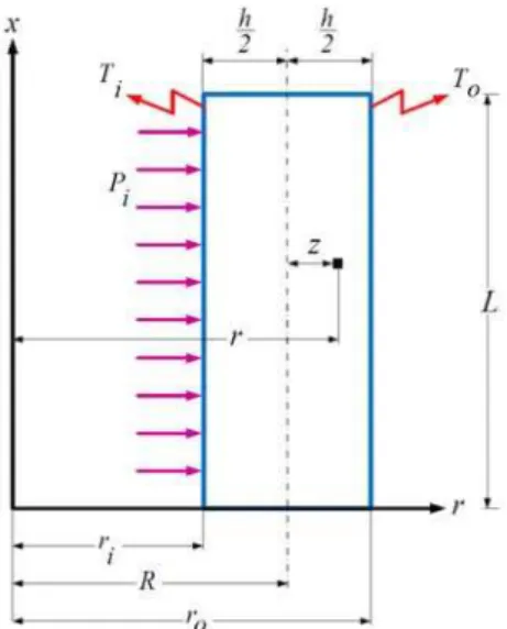
is the radius of every layer of cylinder which can be replaced in terms of radi-us of mid-plane (R)and distance of every layer with respect to mid-plane(z ), as follows (Figure1):
The parameters x and z are the length and the thickness variables which vary in the following intervals:
0 ,
2 2
h h
x L z
(2)
where
h
andL
are the thickness and the length of the cylinder.The displacement field is assumed as a polynomial of a variable
( )
z
through the thickness. As the number of terms in the polynomial function increases, the approximate solution is improved as well. The high-order shear deformation theory (HSDT) is employed to simulate the deformation of every layer of the cylinder.
Figure 1: Geometry of the thick cylindrical shell under internal pressure and temperature gradient.
Based on HSDT, every component of deformation can be stated by variables that include the displacement and rotation. For an axisymmetric cylindrical shell, axial and radial components of displacement field are assumed to be in the following form:
2 3
0 1 2 3
2 3
0 1 2 3
0
( ) ( ) ( ) ( )
( ) ( ) ( ) ( )
x
z
U u x zu x z u x z u x
U
U w x zw x z w x z w x
(3)
where u x0( ) and w0( )x are the displacement components of the middle surface. u xi( ) and
( )
i
w x for i 0,1, 2, 3 are the unknown functions of
x
which are used to determine the displace-ment field.2 3
0 1 2 3
2 3
0 1 2 3
2
1 2 3
2 3
0 1 2 3
1 2 3
2 3
2 3
x x
z
z z
x z
xz
du du
U du du
z z z
x dx dx dx dx
w w z w z w z
U
r R z
U
w w z w z
z
dw dw
U U dw dw
u u z u z z
z x dx dx dx dx
(4)
Considering the dimensionless radial coordinate
r as the ratio of radial coordinate
r upon internal radius
ri :i
r r
r
(5)
Mechanical and physical properties of inhomogenous and isotropic material (FGM) including modulus of elasticity
E , thermal expansion coefficient
and thermal conductivity coefficient
K are supposed to be a power function of dimensionless radial coordinate:
( ) i n
E r E r (6a)
( )r i r n
(6b)
( ) i n
K r K r (6c)
Here Ei, i and Ki are the modulus of elasticity, thermal expansion coefficient and thermal
conductivity coefficient at the inner surface
ri of the cylinder and n is the inhomogeneity con-stant of FG material determined empirically. Generally speaking, the Poisson’s ratio
for a thick-walled cylindrical pressure vessel of isotropic FGM varies in a small range. Furthermore, its effects on mechanical stresses are insignificant. For simplicity, the Poisson’s ratio is assumed to be con-stant.The distribution of material properties from Eqs. (6) can be re-written as a function of z by substituting
r
from Eq. (1) into Eq. (5):( )
n
i i
R z
E z E
r
(7a)( )
n
i i
R z z
r
( )
n
i i
R z
K z K
r
(7c)Figure 2 shows the distribution of dimensionless material properties
X Xi
with respect to thedimensionless radius in a heterogeneous cylinder for integer values of nwhich vary in the range of
2 n 2
.
. . .
. . . . .
X
Figure 2: Distribution of dimensionless material properties in an FGM cylinder.
On the basis of the constitutive equations for inhomogeneous and isotropic materials, the stress components based on components of mechanical and thermal strain are as follows:
( )
2 0 0 0
( )
2 0 0 0
2 0 0 0 ( ) ( ) ( )
1 2
0 0 0 0 0 0 0
0 0 0 0 0 0 0
0 0 0 0 0 0
x x
z z
x x
z z
x z xz
T z T z T z z E z
(8)
where
and
are the Lame’s constants. Considering variable elasticity modulus for the FGM materials, these two parameters are as follows:
( )
1 1 2
E z
(9)
( )
1
2 E z
(10)
The axial forces based on normal components of stress are as follows: 2 2 1 1 x x h h z z R R
z
N
N
dz
N
z
(11)The bending moments based on normal components of stress are as follows:
2 2 1 1 x x h h z z R R
z
M
M
zdz
M
z
(12)The higher-order bending moments based on normal components of stress are as follows:
2 2 2 1 1 x x h h z z R R
z
P
P
z dz
P
z
(13) 2 3 2 1 h x x h Rz
S
z dz
S
(14)The shear force based on shear stress is as follows:
2 2 1 h x xz h R
z
Q
dz
(15)The torsional moment based on shear stress is as follows:
2 2 1 h xz xz h R
z
M
zdz
(16)2 2 2 1 h xz xz h R
z
P
z dz
(17) 2 3 2 1 h xz xz h Rz
S
z dz
(18)3 VIRTUAL WORK PRINCIPLE
Based on the principle of virtual work, the variation of strain energy of the elastic body
U is equal to the variation of external work due to pressure
W .U W
(19)The strain energy is
* * , 1 1 2 2 V Tx x z z xz xz
U U dV dV rdrd dx R z dxd dz
U
(20)and the external work consists of internal and external pressure (
P
iand Po) , which is:
zsf S
o o i i sf
W dS dS d dx
P U
r f u
dS r P r d dx
f u
, (21)where fsf is the surface force of the pressurized cylinder.
The bounds of integrals for
x
andz
variables have been defined in Eq. (2). Variation of the strain energy can be expressed as follows:2 / 2
*
0 0 / 2 / 2
0 / 2 1
( ) 1
2
L h
h L h
x x z z xz xz
h
z
U R U dzdxd
R U z R dzdx R
(22)and the variation of the external work is:
0 0
0
2
2 2 2
z
z
L
i i o o
L
i o
W U dxd
W
U dx
P r P r
h h
P R P R
Substituting Eqs. (4), (7) and (8) into Eqs. (22) and (23), using Eq. (19) and carrying out the integration by parts, the equilibrium equations for the cylindrical shell with constant thickness un-der one-dimensional heat transfer and uniform internal and external pressure are obtained in the form of: 3 3 0 0 1 1 2 2 3 3 0 0 1 1 2 2 2 3 2 3 P T x P T x x P T x xz P T x xz P T x P T xz z P T xz z P T xz z x x x x x x x x z z z z z z z z dN
R F F
dx dM
R RQ F F
dx dP
R RM F F
dx dS
R RP F F
dx dQ
R N F F
dx dM
R M RN F F
dx dP
R P RM F F
dx dS
R S RP F F
dx (24)
where P
F
and TF
stand for non-homogeneity of the governing equations which have resulted from the loading of pressure and temperature, respectively. The subscripts x and z in the right terms of each equation show the components of PF
and TF
along the axial and radial direction, respec-tively.2 0
0,1, 2, 3 1 i i P P i sf h z x z F i z
F Rf z
R
(25)
2 1 2 0 0,1, 2,3 ( ) ( ) ( ) ( 1) 1 2 i i T hT i i
h x
z
F
i z E z T z
F
i z iRz dz
(26)The boundary conditions at the two ends of the cylinder are:
0 1 2 3 0 1 2 3 0
0
L
x x x x x xz xz xz
4 HEAT TRANSFER EQUATION
According to Figure 1, heat transfer in the form of conduction along the thickness of the cylinder under the effect of heat sources at the internal and external surface causes thermal strains. For thermo-elastic analysis of the cylinder, the function of temperature gradient distribution along the longitudinal direction should be determined by the solution of heat transfer equation. Fourier’s heat transfer law in general form is:
2
K r T q
C T (28)
where T , K r
, q,
and Care temperature distribution, thermal conduction coefficient, heat generation rate, density and specific heat, respectively.In cylindrical coordinate system, the Eq. (28) could be re-written in the form of:
2
1
1
p
T T T
K r K r K r q C T
r r x
r
r
r
r
x
(29)Axisymmetric thermal load in cylindrical coordinate system causes just radial flow in the cylin-der. Therefore, Eq. (29) for radial temperature distribution in steady-state condition without any heat generation has been simplified as:
( ) T 0
K r r
r r
(30)
Thermal boundary conditions, as shown in Figure 1, consist of temperatures at the internal and external surfaces of the cylinder:
( ) , ( )
i o
r r i r r o
T r T T r T (31)
Solution of differential Eq. (30) by applying thermal boundary conditions according to Eq. (31) and considering coefficients of thermal conduction from Eqs. (6- c) yield to the temperature distri-bution along the thickness of the cylinder as a function of radius:
( )
n
i o o i o i
n n n
n n
i o
i o
r r T T T T
T r
r r r
r r
(32)
Since the terms of temperature gradient distribution appear in the thermal part of non-homogeneity in Eq. (26)
TF , Eq. (32) should be re-written in the terms of T z( ):
( )
(
)
n o
i o i o i
n n n
n n
o i
o i
r r
T
T
T
T
T z
R z
r
r
r
r
where Ti and To are the temperature gradients between the environment of the cylinder and internal and external surfaces, respectively. Considering
T
ref as the temperature of environment (reference), we have:,
i i ref o o ref
T T T T T T
(34)
5 ANALYTICAL SOLUTION
Eqs. (24) are the set of differential equations. In order to solve these equations, forces and moments could be written by using Eqs. (11) to (18) in terms of stresses. The stresses could be written in terms of strains by substituting Eqs. (7– a and b) into Eq. (8) and using Eq. (33). By using Eqs. (4), the strains are converted into the displacement filed components. Finally, a set of linear non-homogenous differential equations with constant coefficients would result, as follows:
22
d d
A y B y C y F
dx dx (35)
where
A
8 8 ,
B 8 8 and
C 8 8 are the coefficient matrices and
F
is the force vector, which can be expressed as the set of non-homogeneity of differential equations'.
y
is the unknown vector including the components of displacement field as:
0 1 2 3 0 1 2 3
T
y u u u u w w w w (36)
Matrix C in the Eq. (35) whose reverse would be needed in the next calculations is irreversi-ble. In order to make 1
C
, the first equation in the set of Eqs. (24) has been integrated.
0
x
RN C (37)
In Eqs. (24), it is apparent that u0 does not exist, but du dx0 does. In order to calculate de-formations in Eqs. (4), du dx0 is needed. Therefore, by assuming du dx0
as a new parameterwhich could be indicated in the following terms, we have:
0 15
u
vdx C (38)Applying the mentioned changes, the unknown vector
y in the set of differential Eqs. (24) would be rewritten as follows:
1 2 3 0 1 2 3
T
y
v
u
u
u
w
w
w
w
(39)
0 0
1 1
2 2
3 3
0 0
1 1
2 2
3 3
0
P T
P T
P T
P T
P T
P T
P T
P T x x
x x
x x
x x
z z
z z
z z
z z
F F C
F F
F F
F F
F
F F
F F
F F
F F
(40)
The corresponding coefficient matrices
A ,
B and
C of the new differential Eqs. (35) have been defined in appendices.The solution of Eqs. (35) consists of general and particular parts:
y
y
g
y
p (41)For the general solution,
mxg V
y e is substituted in homogeneous Eq. (26).
2 0
mx
e m A m B C V (42) Considering that mx
e
is not equal to zero, the following determinant which is equal to zero would result.2 0
m A m B C (43) The above determinant is a sixteen-order polynomial which is a function of m . The
determi-nant's roots are the eigenvalues miconsisting of eight pairs of conjugated roots where a pair of the roots is zero. Substituting the calculated eigenvalues in Eq. (42), the corresponding eigenvectors
V iare obtained. Therefore, the general solution has been obtained.
14
1
i
m x i
g i
i
y
C V
e
(44)Given that
F in Eq. (35) consists of constant parameters, the non-homogenous part of the so-lution for axisymmetric cylinder with constant thickness under uniform pressure is not the function ofx
. Therefore, the particular solution can be expressed as follows.
1p
p
C y F y C F (45)
0
0 1 2 3 0 1 2 3
0
0 1 2 3 0 1 2 3
0 u u u u w w w w
u u u u w w w w
x
x L
(46)Applying eight boundary conditions at each end of the cylinder, one can calculate sixteen con-stants comprised of
C
1,
,
C
14 in the general solution andC C
0,
15 in the particular solution. Final-ly, the unknown vector
y
which consists of displacement field components would be obtained in terms ofx
variable based on Eq. (41) by determining unknown constants. Using Eq. (3) would yield radial and axial displacements. Stress distribution would be obtained by using Eqs. (4) and (8).6 NUMERICAL RESULTS AND DISCUSSIONS
As a case study, a thick heterogeneous cylinder under uniform internal pressure and heat conduc-tion resulting from temperature gradient of internal and external surfaces and clamped-clamped boundary conditions at the two ends with the following characteristics could be considered:
40 mm
i
r , h 20 mmand L 0.8 m. The values of elasticity modulus, thermal expansion
coeffi-cient and thermal conductivity coefficoeffi-cient at the internal radius are Ei 200 GPa,
6 o
C
12 10
i
andW m.K 20
i
K , respectively. The value of Poisson’s ratio is 0.3. The
applied internal pressure is Pi 80 MPa. The temperatures of internal and external surfaces are
o
C
125 i
T and To 25 oC, respectively. The environment (reference) temperature is Tref 25oC.
The analytical solution has been carried out by writing the program in MAPLE 17.
have been exerted by preventing the nodes around the two ends of the cylinder from movement. In the next sections, the numerical and analytical results have been investigated.
6.1 Loading and Inhomogeneity Effect
The distribution of the dimensionless radial displacement resulting from the numerical and analyti-cal solution in the middle of a cylinder under 100 Co temperature gradient is depicted in Figures 3
and 4 without and with internal pressure, respectively. It is evident that radial displacement under temperature gradient for negative values of n is higher than the homogenous materials at layers close to the internal surface while at the outer surface, reverse holds true. For positive values of n, the reverse holds true, which means that the heterogonous materials have lower values of radial displacement than the homogenous ones at inner surfaces and the higher values of displacement at outer surfaces. The variation in the displacement of heterogeneous materials is similar to that of homogenous materials close to the middle layer. Under thermal and mechanical loads for negative values of n, the displacements of FGM cylinders are higher than those of the homogeneous cylinder. For positive values of n, the situation is reverse, i.e. the displacement is lower. Figure 4 shows that radial displacements for different values of n increase from internal layer to the middle layer while in the external half of the cylinder's thickness, they decrease around the middle layer to the exter-nal layer. Variation of inhomogeneity constants from negative to the positive causes maximum dis-placement of cylinder's thickness to appear around the external layer. Furthermore, adding internal pressure to the temperature gradient causes uniform displacement along the radial direction. From the viewpoint of low level and small variation of displacements, using materials with negative in-homogeneity constants for thermal loading and positive for mechanical loading is recommended.
. . . . .
. . . . .
HSDT
FEM
Figure 3: Dimensionless radial displacement distribution in the middle of the cylinder
under temperature gradient
o
100 C T
. . . . . . . .
. . . . .
HSDT FEM
Figure 4: Dimensionless radial displacement distribution in the middle of the cylinder under internal pressure and temperature gradient
o
100 C T
.
Figures 7 and 8 show the distribution of the dimensionless circumferential stress resulting from the numerical and analytical solution at x L 2 for 100 Co temperature gradient under pressurized
and non-pressurized cylinder, respectively. For both loadings, the circumferential stress for negative values of n is higher than the homogenous materials at layers close to the internal surface while at
the outer surface, reverse holds true. For positive values of n, the reverse holds true, suggesting that
the heterogonous materials have less values of circumferential stress than the homogenous ones at inner surfaces and the higher values of stress at outer surfaces. Considering more uniform stress distribution of the layers and less maximum values of stress for n0 under combined loading, it is interesting to use FG materials with negative values of n. Internal pressure causes an increase in the
values of circumferential stresses, which would result in positive values of stresses around the inter-nal layer.
‐ ‐
‐ . . . . .
HSDT FEM
Figure 5: Dimensionless circumferential stress distribution in the middle of the cylinder
under temperature gradient
o
100 C T
‐
‐ . . . . .
HSDT FEM
Figure 6: Dimensionless circumferential stress distribution in the middle of the cylinder under internal pressure and temperature gradient
o
100 C T
.
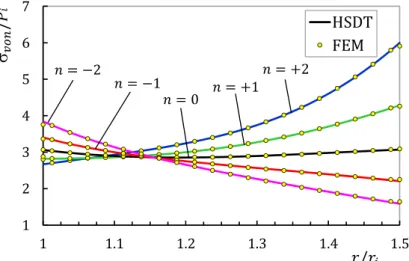
Distribution of von Mises stress resulting from numerical and analytical solution in the middle of the cylinder for thermal loading
o
100 C T
is illustrated in Figure 7. It can be seen that von Mises stresses at internal layer are equal for different inhomogeneities and for negative ones a de-crease in the value of stresses appears along the thickness relative to external layer. n0 causes higher values of von Mises stresses relative to the homogenous materials while for n 0 the reverse hold true. Considering temperature gradient, von Mises stress at the internal half of the cylinder decreases along the thickness from the internal layer to the external one for all inhomogenous mate-rials, while it increases for positive values of n and is constant for negative ones at the external half.
. . . . .
HSDT FEM
Figure 7: Dimensionless von Mises stress distribution in the middle of the cylinder
under temperature gradient
o
100 C T
Figure 8 shows the numerical and analytical distribution of von Mises stress under combined loading at x L 2. The comparison of Figures 7 and 8 clearly shows that adding internal pressure to the temperature gradient results in different values of von Mises stress at the internal layer, i.e. around the internal layer. Corresponding stress of negative inhomogeneous materials has maximum values while around the external layer, materials with positive inhomogeneities have maximum val-ues. Applying internal pressure to the cylinder under temperature gradient causes less values of von Mises stress around the internal layer and more values around the external one for n 0. It could easily be seen that FGMs with negative values of n are more appropriate from the viewpoint of less
von Mises stress.
. . . . .
HSDT FEM
Figure 8: Dimensionless von Mises stress distribution in the middle of the cylinder under internal pressure and temperature gradient
o
100 C T
.
Figure 9 shows the distribution of shear stress resulting from analytical solution along the longi-tude of cylinder under combined load for n 1 in different layers. It can be seen that there are
Figure 9: Shear stress distribution in different layers under internal pressure and
temperature gradient
o
100 C T
for n 1.
. . .
. . . .
HSDT FEM
Figure 10: Dimensionless radial displacement distribution at z h 2 under internal pressure and temperature gradient
o
100 C T
.
. . . .
HSDT FEM
Figure 11: Dimensionless von Mises stress distribution at z h 2 under internal pressure and temperature gradient
o
100 C T
6.2 Temperature Gradient Effect
The effect of temperature gradient on radial displacement for n 1 has been investigated in
Fig-ure 12. It could be observed that for n 1, the same graph is obtained. It can be seen that
in-creasing temperature gradient leads to increment in values of radial displacements. This increment is equal from the internal layer to the external one for lower gradient temperature while it is higher in the external layers for upper gradient temperature for inhomogenous materials.
The effect of temperature gradient on von Mises stress has been investigated in Figures 13 and 14 for n 1. The von Mises stresses, as the radial displacements, for both positive and negative
values of n are uniform through the thickness in lower temperature gradient. The increment of
temperature gradient yields higher stress values. Upper temperature gradient has brought about higher values of stresses around the internal and external layers and low levels of stresses around the middle layer for n 1while it causes reductions in stresses from the internal to the external
layer for n 1. Therefore, the increment of temperature gradient yields higher displacement and
stress along the thickness of the cylinder.
. . . . . . . .
. . . . .
HSDT FEM
Figure 12: Dimensionless radial displacement distribution in the middle of the cylinder under different temperature gradient for n 1.
. . . . .
HSDT FEM
. . . . .
HSDT FEM
Figure 14: Dimensionless von Mises stress distribution in the middle of the cylinder under different temperature gradient for n 1.
6.3 Third-order Approximation Effect
Tables 1 and 2 present the radial and von Mises stresses of different layers resulting from different solutions in the middle of heterogeneous cylinder (x L 2) under internal pressure, respectively.
The radial and von Mises stresses of different layers resulting from different solutions in the middle of the heterogeneous cylinder (x L 2) under o
100 Ctemperature gradient are presented in Tables
3 and 4, respectively. The stresses resulting from internal pressure increase from the external layer to the internal one whereas FG materials with positive inhomogeneities yield lower values of the maximum stresses. It has been shown that FSDT method has acceptable results for displacements, but the radial and von Mises stresses resulting from FSDT show a significant difference once com-pared with the results calculated from HSDT and FEM solution. This difference increases at layers close to the boundaries and the greatest difference occurs in the internal surface
z h 2
whileusing HSDT yields the values of -80 and 0 for radial stresses at the internal and external layer, re-spectively, which is compatible with applying pressure. In the cylinder under temperature gradient, the radial stresses at different layers have negative values which are inconsiderable relative to the stresses of pressurized cylinder.
, MPa
r
n 1 n0 n 1
HSDT FSDT FEM HSDT FSDT FEM HSDT FSDT FEM
/ 2
z h -77.751 7.228 -80.000 -77.211 6.738 -80.000 -76.347 6.114 -80.000
/ 4
z h -47.322 -14.019 -46.514 -50.836 -12.349 -49.782 -54.364 -10.700 -52.920
0
z -24.759 -27.337 -24.826 -28.158 -27.619 -28.164 -31.723 -27.516 -31.610
/ 4
z h -9.633 -35.801 -10.198 -11.321 -40.112 -12.168 -13.014 -44.331 -14.333
/ 2
z h -1.135 -41.180 0.000 -1.754 -50.523 0.000 -2.824 -61.146 0.000
, MPa
Von
n 1 n0 n 1
HSDT FSDT FEM HSDT FSDT FEM HSDT FSDT FEM
/ 2
z h 291.64 246.61 289.50 249.67 204.72 250.90 212.26 167.66 216.12
/ 4
z h 209.60 193.12 209.27 199.50 180.35 199.01 188.01 166.16 187.31
0
z 154.72 155.25 154.84 161.98 161.09 162.04 167.47 164.90 167.48
/ 4
z h 117.48 127.53 117.73 134.46 145.56 134.84 151.79 163.89 152.36
/ 2
z h 92.090 93.477 92.412 115.00 132.83 114.31 141.79 163.14 139.48
Table 2: von Mises stress of different layers under internal pressure at x L 2 based on SDT and FEM.
, MPa
r
n 1 n0 n 1
HSDT FSDT FEM HSDT FSDT FEM HSDT FSDT FEM
/ 2
z h -10.428 247.200 0.000 -6.941 248.026 0.000 -5.055 249.363 0.000
/ 4
z h -9.267 216.230 -13.032 -12.319 244.071 -14.964 -15.101 276.114 -17.096
0
z -13.412 192.083 -13.109 -16.728 240.910 -16.742 -21.064 302.866 -21.228
/ 4
z h -10.237 172.744 -7.630 -12.852 238.319 -10.720 -16.786 329.617 -14.973
/ 2
z h 5.263 156.915 0.000 4.440 236.161 0.000 3.892 356.369 0.000
Table 3: Radial stress of different layers under o
100 C temperature gradient at x L 2 based on SDT and FEM.
,
Von MPa
n 1 n0 n 1
HSDT FSDT FEM HSDT FSDT FEM HSDT FSDT FEM
/ 2
z h 257.43 118.58 255.81 260.66 118.97 264.34 263.22 119.31 273.28
/ 4
z h 137.60 101.86 136.02 165.15 114.97 163.95 197.88 129.77 196.94
0
z 86.270 89.181 86.172 112.19 111.84 112.11 148.31 140.32 148.24
/ 4
z h 81.040 79.259 80.329 108.86 109.34 108.41 146.90 150.94 146.70
/ 2
z h 84.500 71.294 87.278 130.83 107.29 132.63 201.17 161.62 201.17
Table 4: von Mises stress of different layers under o
100 C temperature gradient at x L 2 based on SDT and FEM.
It is generally observed that modifying initial approximation of displacement field components in comparison with FSDT, HSDT yields error reduction. The reason is that FSDT assumes linear distribution for the radial displacement while according to the Lame's theory (PET), the variation of radial displacement along the thickness of the cylinder has hyperbolic distribution.
2 1 ( ) r
C
U r C r
r
(47)
easi-ly be seen that around the middle layer, lower approximation has acceptable results. However, around the internal and external layers, FSDT yields different distributions resulting from Eq. (47). This phenomenon intensifies for thermal loading because displacement distribution along the thick-ness changes from linear status to nonlinear one. The polynomial distribution of displacement in third-order approximation improves the accuracy of the results. The calculus of stresses from placements and strains by using constitutive relations intensifies the initial error appearing in dis-placements.
. . . . . . . . .
. . . . .
HSDT FEM FSDT
Figure 15: Dimensionless radial displacement distribution in the middle of the cylinder based on HSDT, FSDT and FEM for n 1.
7 CONCLUSIONS
causes the external layer to be critical from the viewpoint of displacement and internal layer from the viewpoint of stress. It can be concluded that using FSDT for thermoelastic analysis of cylindri-cal shells, because of disregarding third approximation terms in displacement field components, is not appropriate. Therefore, third-order approximation yields improved accuracy, especially around the boundary layers. Because the terms resulting from pressure and temperature gradient have been revealed in the non-homogeneity part of the set of governing differential equations, the superposi-tion principle could be utilized for the effect of combined loading on the basis of linear elasticity. In fact, the non-homogeneity vector
F appears as a force vector in the governing equations.References
Arani, A.G., Kolahchi, R., Barzoki, A.A.M. (2011). Effect of material in-homogeneity on electro-thermo-mechanical behaviors of functionally graded piezoelectric rotating shaft. Applied Mathematical Modelling, 35, 2771–2789. Arefi, M., Rahimi, G.H. (2010). Thermo elastic analysis of a functionally graded cylinder under internal pressure using first order shear deformation theory. Scientific Research and Essays, 5, 1442–1454.
Cao, L.-L., Qin, Q.-H., Zhao, N. (2012). Hybrid graded element model for transient heat conduction in functionally graded materials. Acta Mechanica Sinica, 28, 128–139.
Eipakchi, H.R. (2010). Third-order shear deformation theory for stress analysis of a thick conical shell under pres-sure, J. of Mechanics of materials and structures 5(1): 1-17.
Eipakchi, H.R., Khadem, S.E., Rahimi, G.H. (2008). Axisymmetric stress analysis of a thick conical shell with vary-ing thickness under nonuniform internal pressure, J. Engineervary-ing Mechanics 134: 601-610.
Eipakchi, H.R., Rahimi, G.H., Khadem, S.E. (2003). Closed form solution for displacements of thick cylinders with varying thickness subjected to nonuniform internal pressure, J. Structural Engineering and Mechanics 16(6): 731-748. Fukui, Y., Yamanaka, N. (1992). Elastic analysis for thick-walled tubes of functionally graded materials subjected to internal pressure, JSME, Ser. I 35(4): 891-900.
Ghannad, M., & Gharooni, H. (2015). Elastic analysis of pressurized thick FGM cylinders with exponential variation of material properties using TSDT. Latin American Journal of Solids and Structures, 12(6), 1024–1041.
Ghannad, M., Nejad, M.Z. (2010). Elastic analysis of pressurized thick hollow cylindrical shells with clamped-clamped ends, Mechanika 5(85): 11-18.
Ghannad, M., Rahimi, G.H., Nejad, M. Z. (2012). Determination of displacements and stresses in pressurized thick cylindrical shells with variable thickness using perturbation technique. Mechanika, 18(1), 14–21.
Ghannad, M., Rahimi, G.H., Nejad, M.Z. (2013). Elastic analysis of pressurized thick cylindrical shells with variable thickness made of functionally graded materials, Composites: Part B 45: 388-396.
Jabbari, M., Meshkini, M., Eslami, M.R. (2011). Mechanical and thermal stresses in a FGPM hollow cylinder due to radially symmetric loads. ISRN Mechanical Engineering, 2011, Article ID 291409, 1–9. doi:10.5402/2011/291409 Keles, I., Conker, C. (2011). Transient hyperbolic heat conduction in thick-walled FGM cylinders and spheres with exponentially-varying properties. European Journal of Mechanics A-Solids, 30, 449–455.
Koizumi, M. (1993). The concept of FGM: ceramic transactions, Functionally Graded Materials. 34, 3–10.
Nejad, M.Z., Jabbari, M., Ghannad, M. (2015). Elastic analysis of FGM rotating thick truncated conical shells with axially-varying properties under non-uniform pressure loading. Composite Structures, 122, 561–569.
Nejad, M.Z., Rahimi, G.H., Ghannad, M. (2009). Set of field equations for thick shell of revolution made of function-ally graded materials in curvilinear coordinate system, Mechanika 3(77): 18-26.
Shao, Z.S., Ma, G.W. (2008). Thermo-mechanical stresses in functionally graded circular hollow cylinder with linear-ly increasing boundary temperature. Composite Structures, 83, 259–265.
Shi, Z., Zhang, T., Xiang, H. (2007). Exact solutions of heterogeneous elastic hollow cylinders. Composite Structures, 79, 140–147.
Tutuncu, N. (2007). Stresses in thick-walled FGM cylinders with exponentially-varying properties, J. Engineering Structures 29: 2032-2035.
Xiang, H., Shi, Z., Zhang, T. (2006). Elastic analyses of heterogeneous hollow cylinders. Mechanics Research Com-munications, 33, 681–691.
Xue, C.X., Pan, E. (2013). On the longitudinal wave along a functionally graded magneto-electro-elastic rod. Inter-national Journal of Engineering Science, 62, 48–55.
Yamanoushi, M., Koizumi, M., Hiraii, T., Shiota, I., Eds. (1990). Proceedings of the 1st International Symposium on Functionally Gradient Materials. Sendai, Japan, 273-281.
Zafarmand, H., Salehi, M., Asemi, K. (2015). Three dimensional free vibration and transient analysis of two direc-tional funcdirec-tionally graded thick cylindrical panels under impact loading. Latin American Journal of Solids and Struc-tures, 12(2), 205–225.
Appendices
11 4*4
12 4*421 4*4 22 4*4
A A
A
A A
(A1)
A12 A21 0 (A2)
/ 2
2
11 / 2
1
1 1 , 2, 3, 4
0 else
h
i j
h ij
r
n z
R e z dz i j
A
R
(A3)
/ 2
222
/ 2
1
1 , 1, 2, 3, 4
h
i j ij
h
r
n z
A R ke z dz i j
R
(A4)
11 4*4
12 4*421 4*4 22 4*4
B B
B
B B
(A5)
B22 0 (A6)
21 12T
B B (A7)
/ 2
2
11 / 2
1 1, 2, 3, 4
1 1
1, 2, 3, 4
0 else
h
i j
h ij
r
n z i j
R e z dz
B
R j i
/ 2
3 12/ 2
1
0
1 1 1 1
else h i j ij h r n
B e z j i k R j i k z dz i
(A9)
11 4*4
12 4*421 4*4 22 4*4
C C
C
C C
(A10)
21 12T
C C (A11)
/ 2
/ 2
11 / 2
4
/ 2
1
1
1 1 , 1
1 1 1 else
h h ij h i j h r r n n z
R e dz i j
R C
z
i j R k e z dz
R
(A12)
/ 2 / 2 / 2 2 12 / 2 1 1 , 11 1, 2, 3, 4
0 else h h h j ij h r r n n
e dz i j
C e z j R jz dz i j
(A13)
/ 2 4 222 / 2
1 1
1 1 1 2
, 1, 2, 3, 4
h i j h ij r n
e i j R z i j z z z dz
C R z
i j
(A14)where the parameters
andk
are as follows
1
1 2
i
E
(A15)
1 2
2
k