Abstract
Fluid-coupling effects lead to a complex dynamical behavior of immersed spent fuel assembly storage racks. Predicting their responses under strong earthquakes is of prime importance for the safety of nuclear plant facilities.
In the near-past we introduced a simplified linearized model for the vibrations of such systems, in which gap-averaged velocity and pressure fields were described ana-lytically in terms of a single space-coordinate for each fluid inter-rack channel. Using such approach it was possible to generate and assemble a complete set of differential-algebraic equations describing the multi-rack fluid coupled system dynamics.
Because of the linearization assumptions, we achieved computation of the flow-structure coupled modes, but also time-domain simulations of the system responses. However, nonlinear squeeze-film and dissipative flow effects, connected with very large amplitude responses and/or relatively small water gaps, cannot be properly ac-counted unless the linearization assumption is relaxed. Such was the aim of a previous paper.
Here, our nonlinear model is introduced and tested in order to expose the signifi-cance of the squeeze-film and dissipative effects. The response of a fuel storage pool with several racks submitted to strong seismic excitations applied in different direc-tions are also presented and discussed.
Keywords: Fluid structure interaction, nonlinear flow effects, squeeze-film, spent fuel storage racks, seismic response, differential-algebraic equations, squeeze-film.
1
Introduction
ij ij+1 1 1 + + j i j
i+1
H
Yj+1rack X L Y L ij X ij Y 0
Y
0X
H
iX+1ij ij+1
1 1 + + j i j
i+1
H
Yj+1rack X L Y L ij X ij Y 0
Y
0X
H
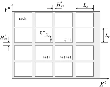
iX+1Figure 1: Geometrical parameters.
can be of the order of 10 m2
connected with very large amplitude responses. Although algebraically involved, the proposed methodology can be automatically implemented on a symbolic computer environment, leading to a system of DAE’s which is then solved through an adequate time-step integration solver.
In the present paper, our nonlinear model [6] is explored by performing two sets of numerical simulations. In the first set and using a small-storage pool with a single centered rack the significance of the squeeze-film and dissipative effects are exposed. In the second set of numerical simulations, the response to a seismic excitation of a storage pool with10racks regularly stored is tested and discussed.
2
Theoretical Model
Consider a pool with M × N nuclear spent fuel racks arranged in M lines and N
columns, which will be described using matrix notation.
The dimensions along the principal directions of each rack cross-section are LX
andLY. TheX- and Y-direction channels (between each pair of racks or between a
wall and a rack) are denoted as
HjX, 1 ≤ i≤M + 1, (1)
HjY, 1 ≤ j ≤N + 1. (2)
In Fig. 1 one can see the main geometrical parameters, for a quite general system configuration.
The motion of each rackX˜ij(t),Y˜ij(t)
,with respect to a global frame can be defined as
˜
Xij(t) = Xij0 +Xij(t), (3) ˜
Yij(t) = Yij0+Yij(t), (4)
where
X0 ij, Y
0 ij
are the coordinates of the geometric centers with respect to the global frame (lower and left walls of the pool container), that is, (Xij(t), Yij(t)) are the
local coordinates of each rack. So, the actual time varying X-direction hX(t) and Y-direction gapshY (t)gaps can be defined as
hXij(t) =HiX+Yi−1j(t)−Yij(t),
1≤i≤M + 1
1≤j ≤N (5)
and
hYij(t) =HjY +Xij(t)−Xij−1(t),
1≤i≤M
1≤j ≤N + 1 (6)
where
by definition.
Following [7], a simplified flow model inside the X-direction and Y-direction channels can be developed from the above-mentioned assumptions [6]. With this ap-proach the gap-averaged velocity and the pressure fields are described, for an incom-pressible flow, in terms of a single space coordinate and the continuity and momentum equations, in each channel. Exact integration of the continuity and momentum equa-tion lead to the pressures pX
ij(x, t) and pYij(y, t) along X-direction and Y-direction
channels. TheX– andY– direction fluid forces acting (per unit length) on each rack was found as
FijX(t) =
LY/2
−LY/2
pYij(y, t)−pYij+1(y, t)
dy, (7)
FijY (t) =
LX/2
−LX/2
pXi+1j(x, t)−pXij(x, t)
dx, (8)
for 1 ≤ i ≤ M and1 ≤ j ≤ N. Note that the 2×M ×N motion dependent flow forces Eqs. (7)-(8) generated by this approach still contain the unknown integration functionsCX
ij (t), CijY (t),pXij (0, t)andpYij(0, t).
Unknowns Number
Xij(t) MN Yij(t) MN CX
ij (t) (M + 1)N
CY
ij(t) M(N + 1)
pX
ij(0, t) (M + 1)N
pY
ij(0, t) M(N + 1)
Total 6MN + 2 (M +N)
Table 1: Total Number of Unknowns.
However, between rack or rack/wall positions ij, ij + 1, i + 1j and i + 1j + 1, one can establish the additional equations we need to obtain this terms, namely,
(M + 1)×(N + 1)−1linearly independent equations of compatibility of flow (mass conservation for all nodes but one), 4×M ×N −(M −1)×(N −1)linearly in-dependent equations of compatibility of pressure (in all corners of each rack except
(M −1)×(N −1)corners) and finally one last equation setting a reference for the pressure.
length). Then, we can deduce the following fluid-structure coupled model:
MsX¨ij+CsX˙ij+KsXij =FijX+Fij,Xaut,
(9)
MsY¨ij+CsY˙ij+KsYij =FijY +Fij,Yaut,
(10)
for 1 ≤ i ≤ M and 1 ≤ j ≤ N where FX
ij, FijY, Fij,Xaut and F
Y
ij,aut represent,
re-spectively, the above-deduced fluid forces and the external autonomous forces per unit length. Here, the structural parameters have been assumed identical for both di-rections. However, dealing with asymmetrical systems bring no further difficulties whatsoever.
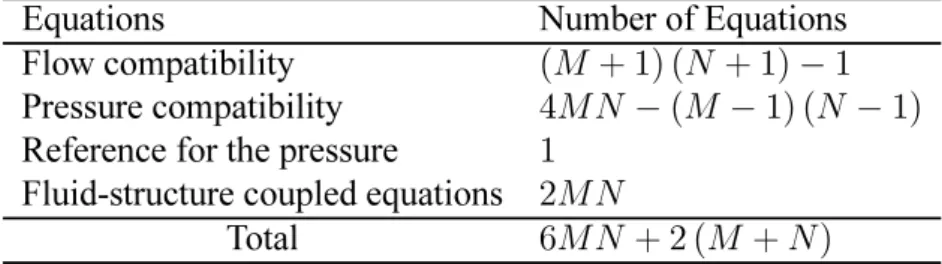
In Table 1 and 2 we summarize the above-mentioned unknowns and equations defining our nonlinear model for the flow-coupled vibratory responses of the system. In [6] one can find all the details of the derivations of our nonlinear model.
Equations Number of Equations
Flow compatibility (M + 1) (N + 1)−1
Pressure compatibility 4MN−(M −1) (N −1)
Reference for the pressure 1
Fluid-structure coupled equations 2MN
Total 6MN+ 2 (M +N)
Table 2: Total Number of Equations.
All these equations represent a set of differential-algebraic equations (DAE’s). That is, among those equations, some of them are pure algebraic constrains between un-knowns. Note that this class of equations arise naturally in many applications but present numerical and analytical difficulties which do not occur with systems of ordi-nary differential equations [8]. In our case the DAE’s developed can be classified as an implicit nonlinear differential-algebraic system of equations
Note that these equations can be written and established for generic systems of
M ×N racks entirely on a symbolic computer environment, as it was done here for the illustrative computations.
3
Numerical Simulations
Define the set of differential-algebraic equations corresponding to our model as
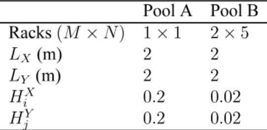
Pool A Pool B Racks(M ×N) 1×1 2×5
LX (m) 2 2
LY (m) 2 2
HX
i 0.2 0.02
HY
j 0.2 0.02
Table 3: Main Geometrical Parameters.
Structural mass,Ms(kg) 32000
Structural damping,Cs(N s/m) 8000
Structural stiffness,Ks(N/m) 5×10
6
Modal frequency in air,fs(Hz) 2
Reduced damping in air,ζ 0.01
Water density,ρ(kg /m3
) 1000
friction factor,f 0.01
Table 4: Physical Modal Parameters.
where v is the vector of unknowns. The simplest first order backward difference formula is the implicit Euler method
F
vn+1−vn tn+1−tn
,vn+1,tn+1
= 0 (12)
in which equation (11) is approximated by finite differences [8]. In the present work we used a fourth and fifth-order generalization of (12) coded in MATLAB [9].
All numerical simulations were performed with the main geometrical, physical and structural modal parameters presented in Tables 3 and 4. The reference time-step used, less than△t = 0.005, was one order of magnitude smaller than1/(2fmax), with
fmax ≈ 20Hz (maximum frequency of the system and/or excitation in our
computa-tion).
As one can observe from Table 3, two sets of numerical simulations were per-formed. One, using a small-storage pool with a single centered rack (pool A) and other set using a pool with ten racks regularly stored in2 lines and5 columns (pool B).
4
Results and Discussion
4.1
Pool A
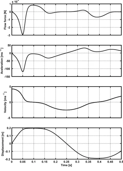
-3 -2 -1 0 1x 10
6 F lo w f o rc e [ N ] -150 -100 -50 0 50 A c e le ra ti o n [ m s -2 ] -5 0 5 V e lo c it y [ m s -1 ]
0 0.05 0.1 0.15 0.2 0.25 0.3 0.35 0.4 0.45 0.5 -0.2 -0.1 0 0.1 0.2 D is p la c e m e n t [m ] Time [s]
flow force exerted on the rack as well as its acceleration and velocity. The simulation was performed using a flow skin friction factor f = 0.01 and a steady fluid gap of
0.2 m. Observing the rack response in we note clearly the occurrence of squeeze-film phenomena, namely, for instance, between 0.05 and 0.16 s. The flow forces, which were computed in each time-step, are maximum at beginning and end of the film-squeezing. Clearly dissipative effects of the flow friction are obvious.
4.2
Pool B
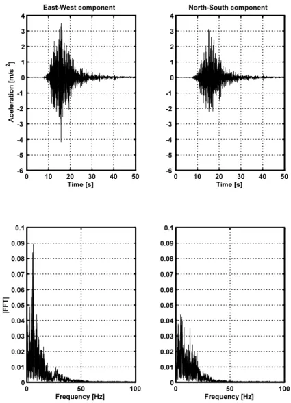
In the second set of numerical simulations, the response to a seismic excitation of a storage pool with10racks regularly stored in 2 lines and in5columns– pool B, are tested. Note that steady fluid gap is now 0.02m. The seismic excitations used were based on the Loma Prieta earthquake in October 17, 1989, projected, in each simula-tion, along one of7different directions varying in steps of15o from theX-direction
(0o degrees) up to the Y-direction (90o degrees). Note that, due the symmetrical
ar-rangement of the racks in the pool, as well as, the symmetry of the structural modal parameters, the behaviour of our system under the same seismic excitation projected along different multiple of15o,falling between90oand360o,can be inferred from the
above mentioned simulations.
The E-W and N-S traces (accelerogram) were obtained and supplied by the Natural Sciences Laboratory at U. C. Santa Cruz and is displayed in Fig. 3.
Angle max|Xij| max|Yij| max Xij2 +Yij2
0o 0.0373 0.0336 0.0428
15o 0.0409 0.0359 0.0435
30o 0.0391 0.0323 0.0410
45o 0.0405 0.0291 0.0433
60o 0.0530 0.0388 0.0542
75o 0.0533 0.0386 0.0539
90o 0.0451 0.0276 0.0452
0 10 20 30 40 50 -6 -5 -4 -3 -2 -1 0 1 2 3 4 East-West component Time [s] A c e le ra ti o n [ m /s 2 ]
0 50 100
0 0.01 0.02 0.03 0.04 0.05 0.06 0.07 0.08 0.09 0.1 |F F T | Frequency [Hz]
0 10 20 30 40 50
-6 -5 -4 -3 -2 -1 0 1 2 3 4 North-South component Time [s]
0 50 100
0 0.01 0.02 0.03 0.04 0.05 0.06 0.07 0.08 0.09 0.1 Frequency [Hz]
Figure 3: Accelerograms and Fourier transforms of the Loma Prieta earthquake in October 17, 1989.
Figure 5: Scaled trajectories of the racks (angle of60o).
The maximum displacement of the racks in each symmetry direction and the max-imum displacement with respect to the initial position of each rack is presented in Table 5. One can observe that for angles of 30o and60o degrees the maximum
dis-placements are respectively minimum and maximum. Notice that although the maxi-mum displacements appear larger than the average fluid gap, which is0.02m, due the compliant motion of the racks, there is never penetration, as it should be.
In Figs. 4 and 5 one can observe the scaled trajectories (in order to make them clearly observable) of each rack for the above-mentioned projection angles of 30o
and60o. The occurrence of the phenomena of squeeze film can be perceived in both
simulations, namely, for instance, observing the trajectories near the walls of rack
(1,5) in Fig. 4 or rack (1,1) in Fig. 5. The phenomenon of squeeze-film is more significant in Fig. 5. For this projection angle of the seismic excitation the different coupled pseudo-modes of our system were more efficiently exited.
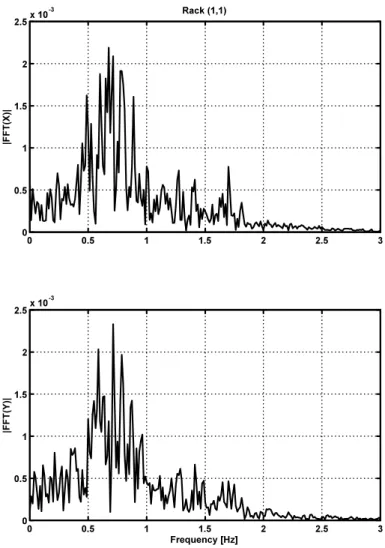
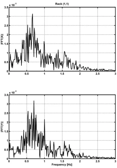
The corresponding spectral response of rack (1,1) for such simulations, can be observed in Figs. 6 and 7. The spectral response display significant different coupled pseudo-modes between 0.5Hz and1Hz. Note that in air the modal frequency of the structure was 2 Hz. This difference is due to the fluid added-mass effect. Observe also, in Figs. 6 and 7, that the overall spectral response of rack(1,1)is diluted over a larger frequency interval (between 0.2Hz and2Hz). This energy spread is due to the nonlinear flow forces related to the large amplitude responses and squeeze-film phenomena.
0 0.5 1 1.5 2 2.5 3 0
0.5 1 1.5 2 2.5x 10
-3 Rack (1,1)
|F
F
T
(X
)|
0 0.5 1 1.5 2 2.5 3
0 0.5 1 1.5 2 2.5x 10
-3
|F
F
T
(Y
)|
Frequency [Hz]
Figure 6: Spectral response of rack (1,1)to the seismic excitation applied along an angle of30o.
5
Conclusion
In this paper we explore a nonlinear model for fluid-coupled vibrations of spent nu-clear racks, based on the main simplifying assumptions: (i) 3-D effects were ne-glected, (ii) small gaps between the fuel assemblies and between these and the con-tainer, when compared with the longitudinal length scales.
Although algebraically involved, the proposed approach can be automatically im-plemented on a symbolic computer environment, leading to a system of DAE’s which is then solved through an adequate time-step integration solver.
This nonlinear 2-D model accounts for squeeze-film and dissipative phenomena related with large amplitude responses and/or small fluid gaps.
0 0.5 1 1.5 2 2.5 3 0
0.5 1 1.5 2 2.5 3 3.5x 10
-3 Rack (1,1)
|F
F
T
(X
)|
0 0.5 1 1.5 2 2.5 3
0 0.5 1 1.5 2 2.5 3 3.5x 10
-3
|F
F
T
(Y
)|
Frequency [Hz]
Figure 7: Spectral response of rack (1,1)to the seismic excitation applied along an angle of60o.
of the true flow added mass effects [2, 10] this model can produce realistic predictions of the displacements and squeeze-film forces taking place on immersed spent fuel racks, when excited by a seismic event, contributing to a better understanding of the complex dynamic behaviour of such systems.
Future work will address 3-D dimensional flow aspects, which are undoubtedly significant in the present context.
References
[1] Broc, D., Queval, J. and T. Chaudat, “Fluid-structure interaction for nuclear
Struc-tures and Fluid/Structure Interactions. Pressure Vessel and Piping Conference, Seattle, USA, July 2000, PVP414-2: 171-177.
[2] Stabel, J. and Ren, M., 2001,“Fluid-structure-interaction for the analysis of the
dynamics of fuel storage racks in the case of seismic loads”,Nuclear Engineering
and Design206: 167:176.
[3] Zhao, Y., Wilson, P. R. and Stevenson, 1996, “Nonlinear 3-D dynamic time
history in the reracking modifications for a nuclear power plant”,Nuclear
Engi-neering and Design165: 199-211.
[4] Hinderks, M., Ungoreit, H. and Kremer, G., 2001, “Improved method to
demon-strate the structural integrity of high density fuel storage racks”, Nuclear
Engi-neering and Design206: 177-184.
[5] Moreira, M. and Antunes, J., 2002, “A simplified Linearized Model for the
fluid-coupled vibrations of spent nuclear fuel racks”,Journal of Fluids and Structures
16(7): 971-987.
[6] Moreira, M. and Antunes, J., 2004, “A nonlinear model for the fluid-coupled
vibrations of spent nuclear fuel racks”,Proceedings of the FIV2004.
[7] Antunes, J. and Piteau, P., 2001, “A Nonlinear model for squeeze-film dynamics
under axial flow”, Proceedings of the ASME Pressure Vessel and Piping
Con-ference, Atlanta, USA, July 2001,420-2: 53-62.
[8] Brenan, K. E., Campbell, S. L. and Pezold, L. R., 1996,“Numerical Solution of
Initial-Value Problems in Differential-Algebraic Equations”, SIAM.
[9] Roberts, A. J., 1998, “Differential - algebraic equations solver DAE” ,-http://www.mathworks.com /support /ftp /diffeqv5.shtml.
[10] Ren, M. and Stabel, J., August 1999, “Comparison of different analytical
for-mulations for FSI between fuel storage racks”, Transactions of the 15th