Flow Induced Vibration, de Langre & Axisa ed. Ecole Polytechnique, Paris, 6-9th
July 2004
A NONLINEAR MODEL FOR FLUID-COUPLED VIBRATIONS
OF SPENT NUCLEAR RACKS
Miguel Moreira
Mathematical Department, College of Technology, Setúbal Polytechnic , Portugal
José Antunes
Applied Dynamics Laboratory, ITN, Lisbon, Portugal
ABSTRACT
In the near-past we introduced a simplified linearized model for the fluid-coupled vibratory responses of nu-clear fuel racks, neglecting three-dimensional flow ef-fects and assuming small gaps between the fuel as-semblies. In this paper, using the same basic ap-proach, we generalize the above-mentioned model to account for nonlinear squeeze-film and dissipative flow effects. The proposed methodology can be au-tomatically implemented on a symbolic computer en-vironment. Numerical simulations highlight the sig-nificance of nonlinear flow effects at high vibration amplitudes, yielding more realistic predictions.
1. INTRODUCTION
Spent fuel storage racks are welded honeycomb stain-less steel structures (generally described as blocks with rectangular walls) with large surfaces (the area of a rack wall can be of the order of 10 m2). They
are used to accommodate spent nuclear fuel assem-blies. The spent fuel racks are placed on a fuel pool freely on the floor and are separated by small water gaps (sometimes down to the order of 10 mm). The fuel pool is filled with water several meters above the top of the racks. Fluid effects induce strong coupling between immersed nuclear fuel racks, when they are subjected to earthquake excitations [see for instance Broc et al (2000); Stabel and Ren (2001); Zhao et al (1996); Hinderks et al (2001)]. Therefore, dur-ing a seismic event, spent fuel storage racks may bend, slide, twist and uplift. Note that, racks are de-signed with short aspect ratios so that they would not tilt over. Undoubted understanding the complex dy-namic behaviour of immersed spent fuel assemblies storage racks under earthquake is of prime impor-tance for the safety of nuclear plant facilities.
In the near-past [Moreira and Antunes (2002)] we introduced a simplified linearized model for the fluid-coupled vibratory responses of nuclear fuel racks based on the following main simplifying assump-tions: (i) Three-dimensional flow effects were
ne-glected; (ii) Gaps between the fuel assemblies and be-tween these and the container were small when com-pared with the longitudinal length-scales; (iii) Dy-namical fluid effects were linearized. From these assumptions, we postulated a simplified flow inside the channels, such that the gap-averaged velocity and pressure fields were described in terms of a single space- coordinate, for each fluid channel. Time-domain simulations of the system responses to seis-mic excitations were also produced and, despite the simplifications introduced, the model yielded qual-itatively similar predictions when compared with other recently published work. However, nonlinear squeeze-film and dissipative effects connected with very large amplitude responses cannot be properly modeled unless assumption (iii) is relaxed. Such is the aim of the present paper. Here, using the same basic approach, we generalize the above-mentioned model to account for nonlinear flow effects. Al-though algebraically involved, the proposed method-ology can be automatically implemented on a sym-bolic computer environment, leading to a system of DAE’s which is then solved through adequate time-step integration solver.
2. MODEL FORMULATION
2.1. Fluid Formulation
Consider a pool withM×N nuclear spent fuel racks arranged in M lines andN columns, which will be described using matrix notation.
The dimensions along the principal directions of each rack cross-section areLX andLY. TheX- and
Y-direction channels (between each pair of racks or between a wall and a rack) are denoted as
HjX , 1 ≤ i≤M + 1, (1)
HjY , 1 ≤ j≤N + 1. (2)
ij ij+1
1 1 +
+ j i
j i+1
HYj+1
rack
X
L
Y
L
ij
X ij
Y 0
Y
0
X
HiX+1 ij ij+1
1 1 +
+ j i
j i+1
HYj+1
rack
X
L
Y
L
ij
X ij
Y 0
Y
0
X
HiX+1Figure 1:Main geometrical parameters.
The absolute positions of each rack
˜
Xij(t),Y˜ij(t)
can be defined as
˜
Xij(t) = Xij0 +Xij(t), (3)
˜
Yij(t) = Yij0+Yij(t), (4)
whereX0 ij, Yij0
are the coordinates of the geomet-ric centers with respect to the pool container, that is,(Xij(t), Yij(t))are the local coordinates of each
rack. So, the actualX-directionhXandY-direction
gapshY can be defined as
hXij =HiX+Yi−1j −Yij,
1≤i≤M+ 1 1≤j ≤N (5)
and
hYij =HjY +Xij−Xij−1,
1≤i≤M
1≤j≤N+ 1 (6)
where
Y0j =YM+1j =Xi0 =XiN+1 = 0
by definition. Note also that
˙
hXij = Y˙i−1j −Y˙ij,
1≤i≤M+ 1 1≤j ≤N , (7)
˙
hYij = Xij˙ −Xij˙ −1,
1≤i≤M
1≤j ≤N+ 1 (8)
and
¨
hXij = Yi¨−1j −Yij,¨
1≤i≤M+ 1 1≤j ≤N , (9)
¨
hYij = X¨ij−X¨ij−1,
1≤i≤M
1≤j ≤N+ 1 .(10)
Following Antunes and Piteau (2000), a sim-plified flow model inside the X-direction and Y -direction channels can be developed from the above-mentionned assumptions. With this approach the gap-averaged velocity and the pressure fields are de-scribed in terms of a single space coordinate and the continuity and momentum equations, in each chan-nel, can be formulated as
∂h ∂t +
∂
∂z(uh) = 0 (11)
and
ρ
∂
∂t(uh) +h ∂ ∂z
u2
+ρu|u|f +h∂p ∂z = 0
(12) where u = u(z, t), h = h(t), p = p(z, t) andz
stand respectively for the fluid velocity, channel gap, pressure and single spatial coordinate along the chan-nel length. The parameterfrepresents an appropriate skin-friction coefficient accounting for the flow/walls distributed stresses. Typically f changes with the flow Reynolds number asf =aRebfor adequate pa-rametersaandb[see, for instance Hirs (1973)].
Integration of the continuity equation (11), leads to the general velocity field for theX-direction and
Y-direction channels as
uXij(x, t) =−
˙
hXij hXijx+C
X
ij, (13)
with1≤i≤M+ 1,1≤j≤N, and
uYij(y, t) =−
˙
hY ij hY
ij
y+CijY, (14)
with1≤i≤Mand1≤j≤N+ 1,whereCijXand
CijY are functions of time stemming from the integra-tion.
The following forms of equation (12) can be de-duced for the X-direction (with 1 ≤ i ≤ M + 1 and 1 ≤ j ≤ N) and Y-direction channels (with 1≤i≤M and1≤j≤N + 1)
∂pXij
∂x = −ρ
1 hX
ij
∂ ∂t
uXijhXij
+2uX ij∂x∂
uX
ij
+h1X ij
uXij u
X ij f
, (15)
∂pYij
∂y = −ρ
1 hY
ij
∂ ∂t
uY
ijhYij
+2uYij∂y∂ uYij
+ 1
hY ij
uY ij
u
Y ij
f
wherepXij andpYijare the pressures alongX-direction andY-direction channels.
Integration of equations (15)-(16) yields for 1 ≤ i≤M+ 1and1≤j≤N
pXij(x, t) =
ρ 2 ¨ hX ij hX ij −2 ˙ hX ij hX ij 2 x2 +ρ ˙ hX ij hX ij CX ij −C˙ijX
x
+ρ3
˙ hXij hXijx−C
X ij 3 ˙ hX ij f
−ρ3|CijX|
3
˙ hX
ij
f+pX ij(0, t)
, (17)
and for1≤i≤M and1≤j≤N + 1
pYij(y, t) =
ρ 2 ¨ hY ij hY ij −2 ˙ hY ij hY ij 2 y2 +ρ ˙ hY ij hY ij
CijY −C˙ijY
y
+ρ3
˙ hYij hY ij
x−CijY
3 ˙ hY ij f
−ρ3|C
Y ij(t)|
3
˙ hY
ij
f+pYij(0, t)
. (18)
The X- and Y- direction fluid forces acting (per unit length) on each rack can be found as follows:
FijX(t) =
LY/2
−LY/2
pYij(y, t)−pYij+1(y, t) dy,
FijY (t) =
LX/2
−LX/2
pXi+1j(x, t)−pXij(x, t) dx,
for1≤i≤M and1≤j≤N, that is,
FijX(t) =
ρ 24 ¨ hY ij hY ij −2 ˙ hY ij hY ij 2
L3Y
−24ρ ¨ hY ij+1 hY ij+1 −2 ˙ hY ij+1 hY ij+1 2
L3Y
+12ρ hYij (h˙Y
ij)
2Ti,jY (t)f
−12ρ h
Y ij+1
(h˙Y ij+1)
2Ti,jY+1(t)f
+ρ3
|CY
ij+1| 3
˙ hY
ij+1 − |C
Y ij| 3 ˙ hY ij f LY
+pY
ij(0, t)−pYij+1(0, t) LY , (19)
withTi,jY (t) =
˙ hY ij hY ij LY
2 −CijY
3˙ hY
ij
hY ij
LY
2 −CijY + ˙ hY ij hY ij LY
2 +CijY
3˙ hY
ij
hY ij
LY
2 +CijY and
FijY (t) =
ρ 24 ¨ hX
i+1j
hX i+1j
−2
˙ hX
i+1j
hX i+1j
2
L3X
−24ρ ¨ hX ij hX ij −2 ˙ hX ij hX ij 2
L3X
+12ρ h X i+1j (h˙X
i+1j)
2TiX+1,j(t)f
−12ρ h
X ij (h˙X
ij)
2Ti,jX(t)f
+ρ3
|CX
ij|
3
˙ hX
ij
−|C
X i+1j|
3
˙ hX
i+1j
f LX
+pX
i+1j(0, t)−pXij(0, t) LX , (20) withTi,jX(t) =
˙ hX ij hX ij LX
2 −CijX
3˙ hX
ij
hX ij
LX
2 −CijX + ˙ hX ij hX ij LX
2 +CijX
3˙ hX
ij
hX ij
LX
2 +CijX .
Note that in equations (17)-(20) ¨
Xij = X˙ij= 0, ifi= 0ori=M+ 1and
¨
Yij = Y˙ij= 0,ifj= 0orj =N + 1,
as (Xij(t), Yij(t)) are the relative coordinates of each rack.
2.2. Formulation of the coupled system
Assuming that the racks are linear systems with struc-tural massMs, dampingCsand stiffnessKs, all these
parameters being per unit length, one can deduce the following fluid-structure model:
MsXij¨ +CsXij˙ +KsXij=FijX+Fij,Xaut,
(21)
MsY¨ij+CsY˙ij+KsYij =FijY +Fij,Yaut,
(22) for 1 ≤ i ≤ M and1 ≤ j ≤ N where FijX, FijY,
Fij,Xaut andFij,Yaut represent, respectively, the
2.3. Formulation of the complete system
Note that the2×M ×N equations (21)-(22) gen-erated by this approach are not sufficient to find all the corresponding unknowns which are summarized in Table 1.
However, between rack or rack/wall positions ij,
ij + 1, i+ 1j and i+ 1j + 1, one can establish the additional equations we need, namely,(M + 1)×
(N + 1)−1linearly independent equations of com-patibility of flow (mass conservation for all nodes but one),4×M×N−(M−1)×(N −1)linearly inde-pendent equations of compatibility of pressure (in all corners of each rack except(M−1)×(N−1) cor-ners) and finally one last equation setting a reference for the pressure.
Unknowns Number
Xij(t) MN
Yij(t) MN CX
ij (t) (M+ 1)N CY
ij(t) M(N + 1) pX
ij(0, t) (M+ 1)N pY
ij(t) M(N + 1)
Total 6MN+ 2 (M+N)
Table 1:Total number of unknowns.
To complete the model formulation, a number of additional algebraic equations must be stated in order to enforce the flow continuity and pressure compati-bility between flow-cells. Here are the compaticompati-bility equations of the flow (or continuity in each corner)
˙
hX
i+1j+1LX+ 2CiX+1j+1hXi+1j+1
+ ˙hYij+1LY + 2CijY+1hYij+1
+ ˙hXi+1jLX−2CiX+1jhXi+1j
+ ˙hYi+1j+1LY −2CiY+1j+1hYi+1j+1
= 0, (23)
where 0 ≤ i ≤ M and 0 ≤ j ≤ N. Note that we must disregard one of these equations in order to obtain a set of(M + 1)×(N+ 1)−1 linearly in-dependent equations. In fact, the flow in a corner is completely determined by the flow in the remaining corners.
The equations of compatibility of pressure estab-lish the following4×M×N−(M−1)×(N−1) relations
pXij(−LX/2, t) = pYij(−LY/2, t), (24) pXij(LX/2, t) = pYij+1(−LY/2, t), (25) pXi+1j(−LX/2, t) = pYij(LY/2, t), (26)
where1≤i≤M,1≤j≤N and
pXi+1j(LX/2, t) =piY+1j+1(−LY/2, t), (27)
where
i=M
1≤j≤N and
1≤i≤M−1
j=N .
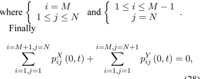
Finally
i=M+1,j=N
i=1,j=1
pXij(0, t) +
i=M,j=N+1
i=1,j=1
pYij(0, t) = 0,
(28) sets a reference for the pressure.
Observe that at the pool walls one has in equations (23)-(27)
¨
Xij = X˙ij= 0, ifi= 0ori=M+ 1and
¨
Yij = Yij˙ = 0,ifj= 0orj =N + 1,
whenever In Table 2 we summarize the above-mentioned equations defining our linearized model for the fluid-coupled vibratory responses of the sys-tem.
Equation Number of Equations (21) MN
(22) MN
(23) (M+ 1) (N + 1)−1 (24)-(27) 4M N −(M −1) (N−1) (28) 1
Total 6M N + 2 (M +N)
Table 2: Equations of the nonlinear model for the fluid-coupled vibratory response of the system.
All these equations represent a set of differential-algebraic equations (DAE’s). That is, among those equations, some of them are pure algebraic constrains between unknowns. Clearly, this is the case of equa-tion (28). Note that this class of equaequa-tions arise natu-rally in many applications but present numerical and analytical difficulties which do not occur with sys-tems of ordinary differential equations Brenan et al (1996). In our case the DAE’s developed can be clas-sified as a nonlinear differential-algebraic system of equations
Note that these equations can be written and estab-lished for generic systems of M ×N racks entirely on a symbolic computer environment as it was done here for the ilustrative computations.
3. NUMERICAL SIMULATIONS
Define the set of differential-algebraic equations cor-responding to our model as
F(˙v,v,t) = 0 (29)
Euler method
F
vn+1−vn tn+1−tn
,vn+1,tn+1
= 0 (30)
in which equation (29) is approximated by finite dif-ferences [Brenan et al (1996)]. In the present work we used a fourth and fifth-order generalization of (30) coded in MATLAB [Roberts (1998)].
In order to validate our nonlinear model, sev-eral numerical simulations were performed over fuel pools with one centered single rack and fuel pools with six racks regularly stored in 2 lines and 3 columns. The present numerical simulations agreed with our previous work, for low vibration amplitudes (with respect to the average gaps), when the lineariza-tion assumplineariza-tions were fulfilled [Moreira and Antunes (2002)]. However when nonlinear flow effects are significant, our new nonlinear model yields much more realistic predictions. Consider two fuel pools (Pool A and Pool B), using dissimilar fluid gaps, each one with six racks regularly stored in 2 lines and3columns. Their response to the same seismic excitation is presented next. The seismic excitation used was the east-west component of the Loma Pri-eta earthquake in October, 1989, applied along the
X-direction (also an axis of symmetry of the storage pools with the racks).
Pool A Pool B
LX(m) 2 2
LY (m) 2 2
HiX 0.2 0.03
HjY 0.2 0.03
Table 3:Main geometrical parameters for the numer-ical simulations.
All numerical simulations were performed with the main geometrical, physical and structural modal pa-rameters presented in Tables 3 and 4. The time-step used△t = 0.005, was one order of magnitude smaller than1/(2fmax), withfmax ≈ 20Hz
(maxi-mum frequency of interest assuming a dominant fre-quency in the seismic spectrum below10Hz). In or-der to provide an appropriate spectral resolution these numerical simulations were performed over an inter-val of 35s.
4. RESULTS AND DISCUSSION
In Figures 2 and 3 we display the spectral response in both directions of the rack in position (1,1) when all the fuel storage pools were submitted to the Loma Prieta earthquake applied along the X -direction. Note that in Pool A the inter-rack gaps and
Structural mass,Ms(kg) 32000
Structural damping,Cs(N s/m) 8000
Structural stiffness,Ks(N/m) 5×10⁶
Modal frequency in air,fs(Hz) 2
Reduced damping in air,ζ 0.01 Rack density, (ρs/ρwater) 8
fricton factor,f 0.01
Table 4: Physical and structural modal parameters for the numerical simulations.
wall/rack gaps are 0.2 m, while in Pool B are only 0.03 m, so that nonlinear squeeze-film and dissipa-tive effects are enhanced.
In spite of the excitation being the same on each rack and only along the direction X responses dis-played in Figures 2 and 3 exhibit motions perpen-dicular to this direction. This is accounted for the presence of a strong fluid-structure interaction, which coupleds all racks and the two motions directions.
In Figure 2 one can observe the spectra response concentrated around1.5Hz. Note that the in air, the modal frequency of the structure was2Hz. This dif-ference is obviously due to the fluid added mass ef-fect.
0 0.5 1 1.5 2 2.5 3 0
1 2 3 4 5 6 7 8 9x 10
-3 Rack (1,1)
|F
F
T
(X
)|
0 0.5 1 1.5 2 2.5 3 0
0.5 1 1.5 2 2.5 3 3.5 4 4.5
5x 10 -3
|F
F
T
(Y
)|
Frequency [Hz]
Figure 2: Pool A. Spectral response of rack(1,1)to
the seismic excitation applied along directionX: (a)
responses along directionXand (b) responses along
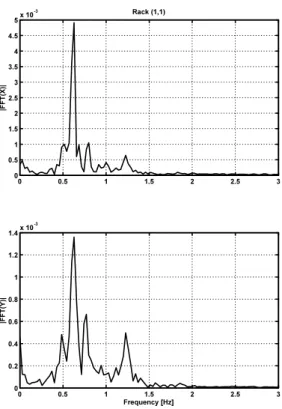
In Figure 3 the spectral response energy of rack (1,1), in both directions, is now diluted over a larger frequency interval (between0.4Hz and1.4Hz). This energy spread is related to the nonlinear flow forces, as a result of the smaller inter-rack and rack/wall gaps, which enhanced the squeeze-film and dissipa-tive effects. Additionally one observe also that the increased fluid added mass lowered even further the response frequencies of our system.
0 0.5 1 1.5 2 2.5 3
0 0.5 1 1.5 2 2.5 3 3.5 4 4.5
5x 10
-3 Rack (1,1)
|F
F
T
(X
)|
0 0.5 1 1.5 2 2.5 3
0 0.2 0.4 0.6 0.8 1 1.2 1.4x 10
-3
|F
F
T
(Y
)|
Frequency [Hz]
Figure 3: Pool B. Spectral response of rack(1,1)to
the seismic excitation applied along directionX: (a)
responses along directionXand (b) responses along
directionY.
5. CONCLUSIONS
In this paper, we propose a generalization of our previous linearized approach [Moreira and Antunes (2002)], introducing a nonlinear model for the fluid-coupled vibratory responses of nuclear fuel racks, ne-glecting three-dimensional flow effects and assum-ing small gaps between the fuel assemblies. The proposed methodology can be automatically imple-mented on a symbolic computer environment. Nu-merical simulations highlighted the significance of nonlinear flow effects at high vibration amplitudes (or small inter-rack and wall/rack gaps). Under such con-ditions, the proposed approach yields more realistic
predictions than our previous work.
6. REFERENCES
Antunes, J. and Piteau, P., 2001, A Nonlinear Model for Squeeze-film Dynamics Under Axial Flow, Pro-ceedings of the ASME Pressure Vessel and Piping Conference, Atlanta, USA, July 2001,420-2: 53-62.
Blevins, R., 1984, Fluid Dynamics, Van Nostrand Reinhold Company, New York.
Brenan, K. E., Campbell, S. L. and Pezold, L. R., 1996, Numerical Solution of Initial-Value Problems in Differential-Algebraic Equations, SIAM.
Broc, D., Queval J and Chaudat, T, 2000, Fluid Struc-ture Interaction For Nuclear Spent Fuel racks, Pro-ceedings of PVP , Emerging Technologies in Fluids, Structures and Fluid/Structure Interactions. Pressure Vessel and Piping Conference, Seattle, USA, July 2000, PVP414-2: 171-177.
Hinderks, M., Ungoreit, H. and Kremer, G., 2001, Improved method to demonstrate the structural in-tegrity of high density fuel storage racks. Nuclear
Engineering and Design206: 177-184.
Hindmarsh, A. C. and Petzold, L. R., 1988, Numeri-cal Methods for Solving Ordinary Differential Equa-tions and Differential/Algebraic EquaEqua-tions, Energy Tech. Rev., September, 23-36, 1988.
Hirs, G., 1973, A Bulk Flow Theory for Turbulence in Lubrificant Films,ASME Journal of Lubrification
Technology,95: 137-146.
Moreira, M. and Antunes, J., 2002, A simplified Linearized Model for the fluid-coupled vibrations of spent nuclear fuel racks.Journal of Fluids and
Struc-tures16(7): 971-987.
Roberts, A. J., 1998, Differential - Algebraic
equa-tions solver DAE, http://www.mathworks.com
/sup-port /ftp /diffeqv5.shtml.
Stabel, J. and Ren, M., 2001, Fluid-structure-interaction for the analysis of the dynamics of fuel storage racks in the case of seismic loads. Nuclear
Engineering and Design206: 167:176.
Zhao, Y., Wilson, P. R. and Stevenson, 1996, Nonlin-ear 3-D dynamic time history in the reracking modifi-cations for a nuclear power plant. Nuclear